1. Page1
The Interface Solution Experts • www.miinet.com
Using MODBUS for
Process Control and Automation
MODBUS is the most popular industrial protocol being
used today, for good reasons. It is simple, inexpensive,
universal and easy to use. Even though MODBUS has
been around since the past century—nearly 30 years—
almost all major industrial instrumentation and automation
equipment vendors continue to support it in new products.
Although new analyzers, flowmeters and PLCs may have
a wireless, Ethernet or fieldbus interface, MODBUS is
still the protocol that most vendors choose to implement
in new and old devices.
Another advantage of MODBUS is that it can run over
virtually all communication media, including twisted pair
wires, wireless, fiber optics, Ethernet, telephone
modems, cell phones and microwave. This means that a
MODBUS connection can be established in a new or
existing plant fairly easily. In fact, one growing application
for MODBUS is providing digital communications in older
plants, using existing twisted pair wiring.
In this white paper, we’ll examine how MODBUS works
and look at a few clever ways that MODBUS can be used
in new and legacy plants.
What is MODBUS?
MODBUS was developed by Modicon (now Schneider
Electric) in 1979 as a means for communicating with
many devices over a single twisted pair wire. The original
scheme ran over RS232, but was adapted to run on
RS485 to gain faster speed, longer distances and a true
multi-drop network. MODBUS quickly became a de facto
standard in the automation industry, and Modicon
released it to the public as a royalty free protocol.
Today, MODBUS-IDA(www.MODBUS.org), the largest
organized group of MODBUS users and vendors, contin-
ues to support the MODBUS protocol worldwide.
MODBUS is a “master-slave” system, where the “master”
communicates with one or multiple “slaves.” The master
typically is a PLC (Programmable Logic Controller), PC,
DCS (Distributed Control System) or RTU (Remote
Terminal Unit). MODBUS RTU slaves are often field
devices, all of which connect to the network in a multi-
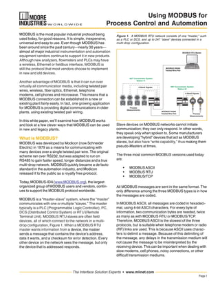
drop configuration, Figure 1. When a MODBUS RTU
master wants information from a device, the master
sends a message that contains the device’s address,
data it wants, and a checksum for error detection. Every
other device on the network sees the message, but only
the device that is addressed responds.
Slave devices on MODBUS networks cannot initiate
communication; they can only respond. In other words,
they speak only when spoken to. Some manufacturers
are developing “hybrid” devices that act as MODBUS
slaves, but also have “write capability,” thus making them
pseudo-Masters at times.
The three most common MODBUS versions used today
are:
• MODBUSASCII
• MODBUS RTU
• MODBUS/TCP
All MODBUS messages are sent in the same format. The
only difference among the three MODBUS types is in how
the messages are coded.
In MODBUS ASCII, all messages are coded in hexadeci-
mal, using 4-bit ASCII characters. For every byte of
information, two communication bytes are needed, twice
as many as with MODBUS RTU or MODBUS/TCP.
Therefore, MODBUS ASCII is the slowest of the three
protocols, but is suitable when telephone modem or radio
(RF) links are used. This is because ASCII uses charac-
ters to delimit a message. Because of this delimiting of
the message, any delays in the transmission medium will
not cause the message to be misinterpreted by the
receiving device. This can be important when dealing with
slow modems, cell phones, noisy connections, or other
difficult transmission mediums.
Figure 1. A MODBUS RTU network consists of one “master,” such
as a PLC or DCS, and up to 247 “slave” devices connected in a
multi-drop configuration.
4-20mA Signals
Process
Measurements
Process
Measurements
MODBUS RTU Master
MODBUS RS485
Twisted Wire Pair
NET Concentrator System
Station #2
NET Concentrator System
Station #1
4-20mA Signals
MODBUS RS485
Twisted Wire Pair
2. Page2
The Interface Solution Experts • www.miinet.com
Using MODBUS for
Process Control and Automation
Table
Addresses
1-9999
10001-19999
30001-39999
40001-49999
Read or Write
Read Only
Read Only
Read or Write
Type Table
Name
Coils
Discrete Inputs
Input Registers
Holding Registers
Figure 3. The literature or operation manuals of most MODBUS-
compatible devices, such as this TMZ Temperature Transmitter
from Moore Industries, publish the addresses of key variables in
the MODBUS Memory Map. The TMZ’s addresses conform to the
MODBUS spec.
Figure 2. Function Codes.
In MODBUS RTU, data is coded in binary, and requires
only one communication byte per data byte. This is ideal
for use over RS232 or multi-drop RS485 networks, at
speeds from 1,200 to 115Kbaud. The most common
speeds are 9,600 and 19,200 baud. MODBUS RTU is the
most widely used industrial protocol, so most of this
paper will focus on MODBUS RTU basics and application
considerations.
MODBUS/TCP is simply MODBUS over Ethernet. Instead
of using device addresses to communicate with slave
devices, IP addresses are used. With MODBUS/TCP, the
MODBUS data is simply encapsulated inside a TCP/IP
packet. Hence, any Ethernet network that supports TCP/
IP should immediately support MODBUS/TCP. More
details regarding this version of MODBUS will be covered
in a later section entitled “MODBUS Over Ethernet.”
MODBUS RTU Basics
To communicate with a slave device, the master sends a
message containing:
• DeviceAddress
• Function Code
• Data
• Error Check
The Device Address is a number from 0 to 247. Messages
sent to address 0 (broadcast messages) can be accepted
by all slaves, but numbers 1-247 are addresses of specific
devices. With the exception of broadcast messages, a
slave device always responds to a MODBUS message so
the master knows the message was received.
on the device
The Function Code defines the command that the slave
device is to execute, such as read data, accept data,
report status, etc. (Figure 2). Function codes are 1 to
255. Some function codes have sub-function codes.
The Data defines addresses in the device’s memory map
for read functions, contains data values to be written into
the device’s memory, or contains other information
needed to carry out the function requested.
The Error Check is a 16-bit numeric value representing
the Cyclic Redundancy Check (CRC). The CRC is gener-
ated by the master (via a complex procedure involving
ORing and shifting data) and checked by the receiving
device. If the CRC values do not match, the device asks
for a retransmission of the message. In some systems, a
parity check can also be applied.
When the slave device performs the requested function, it
sends a message back to the master. The returning
message contains the slave’s address and requested
function code (so the master knows who is responding),
the data requested, and an Error Check value.
MODBUS Memory Map
Each MODBUS device has memory, where process
variable data is stored. The MODBUS specification
dictates how data is retrieved and what type of data can
be retrieved. However, it does not place a limitation on
how and where the device vendor maps this data in its
memory map. Below would be a common example of
how a vendor might logically map different types of
process variable data.
Discrete inputs and coils are one-bit values, and each has
a specific address. Analog inputs (also called “Input
Registers”) are stored in 16-bit registers. By utilizing two
of these registers MODBUS can support the IEEE 32-bit
floating point format. Holding Registers are also 16-bit
internal registers that can support floating point.
Command Function Code
01
02
03
04
05
06
07
08
.
.
xx
Read Coils
Read Discrete Inputs
Read Holding Registers
Read Input Registers
Write Single Coil
Write Single Register
Read Exception Status
Diagnostics
Up to 255 function codes, depending
3. Page3
The Interface Solution Experts • www.miinet.com
Using MODBUS for
Process Control and Automation
Data in the memory map is defined in the MODBUS
specification. Assuming that the device vendor followed
the MODBUS specification (not all do), all data can easily
be accessed by the MODBUS master, which follows the
specification. In many cases, the device vendor publishes
the memory locations (Figure 3), making it easy for the
person programming the master to communicate with the
slave device.
Reading and Writing Data
MODBUS has up to 255 function codes, but 01 (read
coils), 02 (read discrete inputs), 03 (read holding regis-
ters) and 04 (read input registers) are the most commonly
used read functions that are used to collect data from
NET Concentrator System
Distributed I/O
(Analog Input Module)
Figure 4. Home Run Wiring vs MODBUS. In most plants, field instruments connect to the control system with individual “home run”
twisted pairs (below). When the instruments are wired into a distributed I/O system, such as the NCS from Moore Industries (center),
more devices can be added, but only a single twisted pair is needed to transmit all the data to the MODBUS master. Multiple NCS systems
can be networked (bottom) over the same MODBUS network, so the entire plant can be converted from home run wiring to MODBUS.
MODBUS slaves. For example, to read three 16-bit words
of analog data from device 5’s memory map, the master
sends a command that looks something like this:
5 04 2 3 CRC
Where 5 is the device address, 04 says to read input
registers, 2 is the starting address (address 30,002), 3
means to read three contiguous data values starting at
address 30,002, and CRC is the error check value for this
message. The slave device, upon receiving this command,
sends back a response that looks something like this:
5 04 aa bb cc CRC
4. Page4
The Interface Solution Experts • www.miinet.com
Using MODBUS for
Process Control and Automation
Where 5 is the device’s address; 04 is the repeated read
command; aa, bb and cc are the three 16-bit data values;
and CRC is the error check value for this message.
Reading and writing digital inputs and outputs is done in
a similar manner using different read and write functions.
Assuming that the device follows the MODBUS
specification, it is a simple programming task to set up
the master to read and write data, check status, obtain
diagnostic information and perform various control and
monitoring functions.
Connecting MODBUS Devices
One of the easiest ways to bring field devices into a
process control system, PLC or industrial computer is to
simply connect digital and analog I/O into a distributed
I/O system that has MODBUS communication capability.
For example, the NCS (NET Concentrator System) from
Moore Industries allows a user to connect analog and
digital signals remotely, which can then be connected to
a MODBUS master via twisted pair cable. Multiple NCS
systems can be installed in several locations throughout
the plant, all linked by MODBUS (Figure 4).
This solution works for both new and existing plants.
In many existing plants, field instruments typically
connect to the DCS or PLC via “home run wiring,” where
each device is connected with individual twisted pairs
that carry analog signals. With the NCS, one of those
twisted pairs can be used for the MODBUS signal. This
is particularly useful if the plant wants to add additional
field instruments, but does not want to run more wiring
(at an installed cost of $100 per foot). A distributed I/O
system can accommodate all of the existing I/O, or it
can be used just to send data from all the new field
instruments.
In some cases, the control system is not able to deal
with a MODBUS signal. It may be that the legacy control
system is accustomed to dealing with 4-20mA analog
I/O and directly wired digital I/O, and reprogramming the
old system to accommodate MODBUS data would be
difficult. Often, users would like to add new remote
signals to their system without having to run wire or buy
expensive MODBUS interface cards that require extensive
re-programming. In that case, a peer-to-peer solution
works best. For example, the CCS (Cable Concentrator
System) and the NCS (NET Concentrator System) from
Moore Industries both have peer-to-peer communication
abilities.
The NCS and CCS are similar to a distributed I/O module,
but have more built-in intelligence and can be set up in
either a peer-to-peer or peer-to-host configuration.
With a peer-to-peer NCS system (Figure 5), two concen-
trators are used: one in the field and one in the control
room. Field instruments connect to the remote NCS,
which connects to the control room NCS via a single
twisted pair wire. Then, outputs from the control room
NCS are wired into the control system’s existing analog
I/O panel. In this way, the analog signals from the new
field transmitters can be seen in their original analog state
through the plant’s existing analog I/O cards. This makes
programming and commissioning of the new signals less
difficult than programming new digital interface cards.
These peer-to-peer solutions can also accommodate
Figure 5. Peer-to-Peer Wiring. In some cases, the control system is not able to deal with a MODBUS signal. In that case, a peer-to-
peer solution with two NCS systems simply replaces all the home run wiring with a single MODBUS cable. Analog outputs from the control
room NCS are then wired directly into the host system’s I/O card.
DCS
NET Concentrator System
Distributed I/O
(Analog Input Module)
Module
Number
NET Concentrator System
Distributed I/O
(Analog Output Module)
I/O Rack
4-20mA
Signals
Proportional
to Transmitter
Inputs
MODBUS RTU
RS485
Communication Link
4-20mA
Dispersed
Process
Transmitters
5. Page5
The Interface Solution Experts • www.miinet.com
Using MODBUS for
Process Control and Automation
bi-directional communication in which both sides of the
system can have inputs and outputs.
HART via MODBUS
Another challenge for legacy plants is to find an inexpen-
sive and convenient way to take advantage of installed and
“to be installed” HART smart devices. HART stands for
HighwayAddressable Remote Transducer. HART is a
digital protocol that was designed to allow transmitters to
simultaneously transmit digital data and an analog signal
over traditional plant installed copper twisted pair. This
enabled users to configure, interrogate and diagnose
transmitters locally or remotely via any point along the
twisted pair. HART slaves can be wired in a point-to-point
configuration or in a multi-drop configuration. In the point-
to-point configuration, which is the most common, the
HART transmitter varies the current on the analog loop to
represent the desired process variable. While it is
possible to monitor the digital HART data only, in a point-
to-point configuration, it is rarely done. As the transmitter
controls the current, it also has the ability to send multiple
digital pieces of information via the HART data stream.
Both process variable data and digital data can be trans-
mitted by the HART slave or transmitter. This data could
be used to monitor the health of instruments or can be
used by the process control system or asset manage-
ment system to optimize processes, assist in providing
tighter control, or prevent unexpected process hiccups. In
some cases, existing plants may have hundreds of HART-
enabled instruments. Unfortunately, for one reason or
another, many plants never exploited the capabilities of
HART.
In today’s world of asset management, remote diagnos-
tics and advanced control, many plants would like to
extract that digital information, but their control system
and existing wiring can’t accommodate it. The control
system may not be set up or have the capability to
extract HART data from the analog loop. AHART instru-
ment can send up to four process variables via the HART
signal: PV (Primary Variable), SV (Secondary Variable),
TV (Tertiary Variable) and FV (Fourth Variable). Addition-
ally, there are various bits and bytes of status data that
can also be transmitted. However, if the control system
cannot read the additional process variable data – or any
of the other diagnostic and status information—from the
digital HART signal, then that data goes to waste.
Customers certainly have options to get this HART data,
even in legacy and mature plants. Some DCS companies
offer new upgraded analog I/O cards that have the ability
to “pick off” this HART data. However, these cards usually
cost three to five times as much as the traditional analog
I/O cards. Additionally, there are HART mux bricks that
can be installed on existing analog loops that have RS422
and RS485 outputs to asset management systems or
DCSes. Again, these I/O mux bricks can be cost prohibi-
tive. An optional route, using a HART to MODBUS
converter like the HIM (HART Interface Module) from Moore
Industries, is cost effective and allows the flexibility of
monitoring just a few or many loops at reasonable costs.
With a HART interface module that supports MODBUS
RTU communication, all the HART data can be brought to
the control system simply and cost effectively (Figure 6).
The HIM is a smart device that acts like HART master on
the front end and MODBUS RTU slave on the back end.
The HIM extracts all of the digital HART data from the
4-20mA signal without placing a burden on the loop. It then
provides a display, three 4-20mA signals, two relays and
an optional dual MODBUS RTU output. When the
MODBUS option is utilized, the HART data is digitally
mapped to the HIM’s MODBUS memory map where it can
then be polled by a PLC or DCS that is acting as the
MODBUS RTU Master. By multi-dropping various HIM
devices via RS485, this essentially becomes a scaled-
down asset management system for a fraction of the cost.
Wireless MODBUS
A MODBUS network can be set up fairly easily to work
over a wireless link (Figure 7). Essentially, all the wireless
link does is replace the twisted pair cables with a trans-
mitter/receiver at each end of the network. Many wireless
radio manufacturers support the MODBUS protocol.
However, due to some encryption schemes and time
delays that radios and modems use, it is important to
consult with your wireless vendor before making the
assumption that it is supported.
Figure 6. A HART Interface Module (HIM) extracts digital data from
the HART signal and stores it in its MODBUS memory map, so that
any MODBUS master can read it. The original 4-20mA signal is still
wired to the control system as before.
6. Page6
The Interface Solution Experts • www.miinet.com
Using MODBUS for
Process Control and Automation
Obviously the major advantage of wireless MODBUS is
the cost savings in wiring infrastructure. Signals that are
needed from tank farms, well heads, and various other
remote locations have historically been cost prohibitive to
monitor and control.
Fortunately, MODBUS via wireless is transparent to the
control system or host and the slave. Like the systems
described previously for legacy plants, the host system
doesn’t even know that a wireless MODBUS network
exists, because it doesn’t have to deal with it. When a
MODBUS master makes a request to a slave and the
packets arrive at the transmitting radio, that radio will
usually re-order the packets and encrypt them before
transmission. Once the RF (Radio Frequency) packets
are received by the “slave” radio, it de-encrypts them and
puts them back in order to represent a valid MODBUS
Figure 7. A wireless interface, such as the Wireless Link Module
from Moore Industries, replaces the twisted pair with an RF link.
NCS NET Concentrator
System
Distributed
Field Devices
Module
Number
MODBUS
(REMOTE)
WLM Wireless Link
Module
NCS NET Concentrator
System
Control or
Readout System
Module
Number
MODBUS
(MASTER)
WLM Wireless Link
Module
Packet. Assuming that the packet has not been damaged
or corrupted, it will then be sent to the destined slave.
The slave will respond back to the Master and the process
starts again.
Sometimes it is important to pay special attention to a
MODBUS communication parameter called “timeout.”
Timeout is the amount of time that the MODBUS master
will wait for a response from a slave before attempting a
re-transmission. Depending on how well the radio is
communicating, packets can be delayed, causing an
unnecessary amount of retries and re-transmits. With
today’s FHSS (Frequency Hopping Spread Spectrum)
radios, most of these parameters can be massaged for
efficient transfer of MODBUS packets. However, proper
radio site surveys that include signal strength and
spectrum noise analysis can often avoid many
communication hiccups.
MODBUS over Ethernet
MODBUS/TCP is often referred to as MODBUS over
Ethernet. For the most part, MODBUS/TCP is simply
MODBUS packets encapsulated in standard TCP/IP
packets. This enables MODBUS/TCP devices to immedi-
ately and easily connect and communicate over existing
Ethernet and fiber networks. MODBUS/TCP also allows
many more addresses than RS485, the use of multiple
Masters, and speeds in the gigabit range. While
MODBUS RTU has a limitation of 247 nodes per network,
MODBUS/TCP networks can have as many slaves as the
physical layer can handle. Often this number is some-
where around 1,024. Ethernet’s rapid adoption within the
process control and automation industry has allowed
MODBUS/TCP to become the most widely used, fastest
growing and supported industrial protocol over Ethernet.
Although PLC vendors of all sizes have adopted their own
proprietary protocols over Ethernet, almost all of them
support MODBUS/TCP. And for those PLC vendors who
don’t currently support MODBUS/TCP, there are many
companies like Prosoft Technologies and SST that offer
chassis-style slide in MODBUS/TCP communication
cards and stand alone gateways.
Unlike MODBUS RTU and MODBUS ASCII, MODBUS/
TCP will allow multiple masters to poll the same slave
device simultaneously. This is allowed because, over
Ethernet using TCP/IP, multiple messages can be sent,
buffered and delivered without the requirement of token
passing or total bus control, which is often the case with
many RS485 and RS422 protocols.
Putting Control in the Field with MODBUS
So far, we’ve only dealt with simple MODBUS data
acquisition systems. It is also possible to install control
devices in the field that will communicate to the central
control system via MODBUS. The NCS, mentioned above
as a concentrator, also has a powerful CPU (Central
Processing Unit) and real time control kernel that can be
programmed to perform control functions, such as PID,
on/off control, local alarming, complex math equations
diagnostics and alarm monitoring.
Because it has PLC-type logic, PID-type control func-
tions, and advanced computing capabilities, an NCS can
often eliminate the need for a PLC, industrial computer, or
a small DCS for a fraction of the price. While the MODBUS
7. Page7
The Interface Solution Experts • www.miinet.com
Using MODBUS for
Process Control and Automation
protocol doesn’t have the capabilities of other protocols
like FOUNDATION Fieldbus and CIP (Common Industrial
Protocol) it does often fit the need for many applications
where local control is desired.
Another “smart” and control capable MODBUS device, the
MDS Equation Station from Moore Industries, is a multi-
function controller that is able to perform a wide variety of
control functions and calculations. It eliminates the need
for a PLC or large controller for simple, multivariable
control tasks, such as monitoring and controlling pulp
levels in a digester, or performing mass flow calculations
using inputs from various flow, temperature and pressure
transmitters. Up to 127 MDS modules can be installed on
a single MODBUS network to control or collect signals
from around the plant.
PID (Proportional, Integral and Derivative) controllers were
originally standalone non-communicating controllers. As
PLCs and DCSes got smarter, so did the controllers.
Today, many end users still prefer the direct readout and
simple to program style of the single loop controller.
Digital communication protocols like MODBUS may have
added a little more life to these once standalone instru-
ments. By multi-dropping controllers you can now create
your own small distributed control system, Figure 8.
MODBUS: The Universal Interface
While the modern control world continues to grapple with
advanced concepts such as fieldbus and mesh networks,
the simplicity of MODBUS and its ease of implementation
over so many communication media continues to allow it
to be the most widely supported and implemented indus-
trial protocol in the world. When users of existing legacy
control systems discover the need to expand field instru-
mentation or add remote controllers, they very often turn
to MODBUS as a simple solution to complex problems.
Moreover, when there is a need to connect an exotic
device to a control system, using the device’s MODBUS
interface often proves to be easiest method. Although
MODBUS is one of the oldest communication methods, it
is also the most popular—for very good reasons. It’s easy
to use, reliable, inexpensive, and connects to almost
every sensing and control device in the control industry.
MODBUS RTU
RS485
HMI/SCADA
(MODBUS Master)
Figure 8. MODBUS-capable devices, such as the 1/4 DIN 545
Dual Loop PID controller, can put control functions in the field.
Multi-dropping the MODBUS output and sending it to a Windows
based SCADA package creates a small distributed control system.