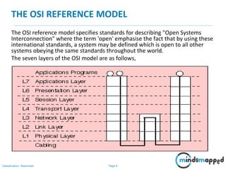
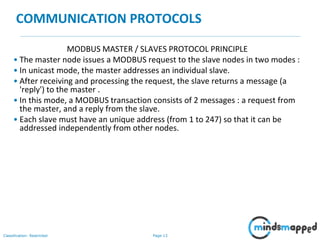
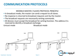
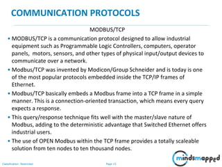
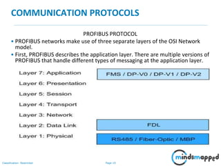
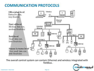
In this session you will learn:
OSI reference model
OSI layers
Modbus communication protocol
Profibus communication protocol
Fieldbus communication protocol
2. Page 2Classification: Restricted
Agenda
• OSI reference model
• OSI layers
• Modbus communication protocol
• Profibus communication protocol
• Fieldbus communication protocol
3. Page 3Classification: Restricted
COMMUNICATION PROTOCOLS
A communications protocol is the set rules for sending blocks of data from one
node in a network to another node.
Protocols are described in a layered manner and provide all or part of the
services specified by a layer of the OSI model.
A protocol specification defines the operation of the protocol and how the
protocol should be implemented.
It consists of three parts:
• Definition of Protocol Control Information (PCI) format which forms the
PDU header.
• Definition of procedures for transmitting and receiving PDUs.
• Definition of services provided by the protocol layers.
A protocol defines the procedures to determine how the PDU will be processed
at the transmit and receive nodes. The procedures specify the valid values for
the PCI , and the action be taken upon reception of each PCI value
4. Page 4Classification: Restricted
THE OSI REFERENCE MODEL
The OSI reference model specifies standards for describing "Open Systems
Interconnection" where the term 'open' emphasise the fact that by using these
international standards, a system may be defined which is open to all other
systems obeying the same standards throughout the world.
The seven layers of the OSI model are as follows,
5. Page 5Classification: Restricted
THE OSI LAYERS
• Physical Layer: Provides electrical, functional, and procedural characteristics
to activate, maintain, and deactivate physical links that transparently send
the bit stream; only recognises individual bits, not characters or
multicharacter frames.
• Data link Layer: Provides functional and procedural means to transfer data
between network entities and correct transmission errors, provides for
activation, maintenance, and deactivation of data link connections, grouping
of bits into characters and message frames, character and frame
synchronisation, error control, media access control, and flow control.
• Network Layer: Provides independence from data transfer technology and
relaying and routing considerations; masks peculiarities of data transfer
medium from higher layers and provides switching and routing functions to
establish, maintain, and terminate network layer connections and transfer
data between users.
6. Page 6Classification: Restricted
COMMUNICATION PROTOCOLS
• Transport layer: Provides transparent transfer of data between systems,
relieving upper layers from concern with providing reliable and cost effective
data transfer; provides end-to-end control and information interchange with
quality of service needed by the application program; first true end-to-end
layer.
• Session layer: Provides mechanisms for organising and structuring dialogues
between application processes; mechanisms allow for two-way simultaneous
or two-way alternate operation, establishment of major and minor
synchronisation points, and techniques for structuring data exchanges.
• Presentation layer: Provides independence to application processes from
differences in data representation, that is, in syntax; syntax selection and
conversion provided by allowing the user to select a "presentation context"
with conversion between alternative contexts.
7. Page 7Classification: Restricted
COMMUNICATION PROTOCOLS
• Application layer: Concerned with the requirements of application. All
application processes use the service elements provided by the application
layer. The elements include library routines which perform interprocess
communication, provide common procedures for constructing application
protocols and for accessing the services provided by servers which reside on
the network.
8. Page 8Classification: Restricted
MODBUS COMMUNICATION PROTOCOL
• Modbus is a serial communication protocol developed by Modicon in 1979
for use with its programmable logic controllers (PLCs).
• In simple terms, it is a method used for transmitting information over serial
lines between electronic devices.
• The device requesting the information is called the Modbus Master and the
devices supplying information are Modbus Slaves.
• In a standard Modbus network, there is one Master and up to 247 Slaves,
each with a unique Slave Address from 1 to 247.
• The Master can also write information to the Slaves.
9. Page 9Classification: Restricted
COMMUNICATION PROTOCOLS
MODBUS COMMUNICATION PROTOCOL
• Modbus is an open protocol, meaning that it's free for manufacturers to build
into their equipment without having to pay royalties.
• It has become a standard communications protocol in industry, and is now
the most commonly available means of connecting industrial electronic
devices.
• It is used widely by many manufacturers throughout many industries.
• Modbus is typically used to transmit signals from instrumentation and control
devices back to a main controller or data gathering system, for example a
system that measures temperature and humidity and communicates the
results to a computer.
• Modbus is often used to connect a supervisory computer with a remote
terminal unit (RTU) in supervisory control and data acquisition (SCADA)
systems.
10. Page 10Classification: Restricted
COMMUNICATION PROTOCOLS
MODBUS COMMUNICATION PROTOCOL
• MODBUS Serial Line protocol is a Master-Slave protocol. This protocol takes
place at level 2 of the OSI model.
• A master-slave type system has one node (the master node) that issues
explicit commands to one of the "slave" nodes and processes responses.
Slave nodes will not typically transmit data without a request from the
master node, and do not communicate with other slaves.
• At the physical level, MODBUS over Serial Line systems may use different
physical interfaces (RS485, RS232). Two-Wire interface is the most common.
As an add-on option, RS485 Four-Wire interface may also be implemented.
RS232 serial interface may also be used as an interface, when only short point
to point communication is required.
11. Page 11Classification: Restricted
COMMUNICATION PROTOCOLS
MODBUS COMMUNICATION PROTOCOL
• MODBUS application layer messaging protocol, positioned at level 7 of the
OSI model, provides client/server communication between devices
connected on buses or networks. On MODBUS serial line the client role is
provided by the Master of the serial bus and the Slaves nodes act as servers.
12. Page 12Classification: Restricted
COMMUNICATION PROTOCOLS
MODBUS MASTER / SLAVES PROTOCOL PRINCIPLE
• The MODBUS Serial Line protocol is a Master-Slaves protocol. Only one
master (at the same time) is connected to the bus, and one or several (247
maximum number) slaves nodes are also connected to the same serial bus.
• A MODBUS communication is always initiated by the master. The slave nodes
will never transmit data without receiving a request from the master node.
• The slave nodes will never communicate with each other. The master node
initiates only one MODBUS transaction at the same time.
13. Page 13Classification: Restricted
COMMUNICATION PROTOCOLS
MODBUS MASTER / SLAVES PROTOCOL PRINCIPLE
• The master node issues a MODBUS request to the slave nodes in two modes :
• In unicast mode, the master addresses an individual slave.
• After receiving and processing the request, the slave returns a message (a
'reply') to the master .
• In this mode, a MODBUS transaction consists of 2 messages : a request from
the master, and a reply from the slave.
• Each slave must have an unique address (from 1 to 247) so that it can be
addressed independently from other nodes.
14. Page 14Classification: Restricted
COMMUNICATION PROTOCOLS
MODBUS MASTER / SLAVES PROTOCOL PRINCIPLE
• In broadcast mode, the master can send a request to all slaves.
• No response is returned to broadcast requests sent by the master.
• The broadcast requests are necessarily writing commands.
• All devices must accept the broadcast for writing function. The address 0 is
reserved to identify a broadcast exchange.
Unicast mode Broadcast mode
15. Page 15Classification: Restricted
COMMUNICATION PROTOCOLS
MODBUS/TCP
• MODBUS/TCP is a communication protocol designed to allow industrial
equipment such as Programmable Logic Controllers, computers, operator
panels, motors, sensors, and other types of physical input/output devices to
communicate over a network.
• Modbus/TCP was invented by Modicon/Group Schneider and is today is one
of the most popular protocols embedded inside the TCP/IP frames of
Ethernet.
• Modbus/TCP basically embeds a Modbus frame into a TCP frame in a simple
manner. This is a connection-oriented transaction, which means every query
expects a response.
• This query/response technique fits well with the master/slave nature of
Modbus, adding to the deterministic advantage that Switched Ethernet offers
industrial users.
• The use of OPEN Modbus within the TCP frame provides a totally scaleable
solution from ten nodes to ten thousand nodes.
16. Page 16Classification: Restricted
COMMUNICATION PROTOCOLS
MODBUS/TCP
• MODBUS® TCP/IP has became an industry de facto standard because of its
openness, simplicity, low cost development, and minimum hardware
required to support it.
• At this moment there are more than 200 MODBUS® TCP/IP devices available
in the market. It is used to exchange information between devices, monitor
and program them.
• It is also used to manage distributed I/Os, being the preferred protocol by the
manufacturers of this type of devices.
• MODBUS TCP/IP uses TCP/IP and Ethernet to carry the MODBUS messaging
structure.
17. Page 17Classification: Restricted
COMMUNICATION PROTOCOLS
ADVANTAGES OF MODBUS/TCP
• It is highly scalable in scope. A collection of devices using MODBUS/TCP to
communicate can range up to 10,000 or more on a single switched Ethernet
network.
• It is simple to administer and enhance. There is no need to use complex
configuration tools when adding a new station to a Modbus/TCP network.
• There is no vendor-proprietary equipment or software needed. Any computer
system or microprocessor with Internet style (TCP/IP) networking can use
MODBUS/TCP.
• It has very high performance, limited typically by the ability of the computer
operating systems to communicate. Transaction rates of 1000 per second or
more are easy to achieve on a single station, and networks can be easily
constructed to achieve guaranteed response times in the millisecond range.
• It can be used to communicate with the large installed base of MODBUS
devices, using conversion products, which require no configuration.
18. Page 18Classification: Restricted
COMMUNICATION PROTOCOLS
PROFIBUS PROTOCOL
• PROFIBUS is not one communication system, but a variety of protocols built
on the same field-bus technology bundle.
• Users can combine varieties of PROFIBUS protocols with their own software
and other requirements, resulting in a unique application profile.
• With many profiles available, PROFIBUS can suit specific needs. One thing
remains the same, though. Through thorough testing, PROFIBUS devices
meet a high standard of quality befitting a high quality network.
19. Page 19Classification: Restricted
COMMUNICATION PROTOCOLS
PROFIBUS PROTOCOL
• PROFIBUS networks make use of three separate layers of the OSI Network
model.
• First, PROFIBUS describes the application layer. There are multiple versions of
PROFIBUS that handle different types of messaging at the application layer.
20. Page 20Classification: Restricted
COMMUNICATION PROTOCOLS
PROFIBUS PROTOCOL
• The data link layer is completed through a Field bus Data Link, or FDL.
• The FDL system combines two common schemes, master-slave methodology
and token passing.
• In a master-slave network, masters, usually the controllers, send requests to
slaves, sensors and actuators. The slaves respond accordingly.
• PROFIBUS also includes token passing, a system in which a “token” signal is
passed between nodes.
• Only the node with the token can communicate. The token passing concept is
like the speaking conch; only the person with the conch is allowed to talk.
21. Page 21Classification: Restricted
COMMUNICATION PROTOCOLS
• PROFIBUS defines a physical layer, though it leaves room for flexibility.
• PROFIBUS systems can have three types of media. The first is a standard
twisted-pair wiring system, in this case RS485.
• Two more advanced systems are also available.
• PROFIBUS systems operating using fiber-optic transmission in cases where
that is more appropriate.
• A safety-enhanced system called Manchester Bus Power, or MBP, is also
available in situations where the chemical environment is prone to explosion.
22. Page 22Classification: Restricted
COMMUNICATION PROTOCOLS
TYPES OF PROFIBUS
PROFIBUS FMS
• The initial version of PROFIBUS was PROFIBUS FMS, Fieldbus Message
Specification.
• PROFIBUS FMS was designed to communicate between Programmable
Controllers and PCs, sending complex information between them.
• Being the initial effort of PROFIBUS designers, the FMS technology was not as
flexible as needed. This protocol was not appropriate for less complex
messages or communication on a wider, more complicated network.
• New types of PROFIBUS would satisfy those needs. PROFIBUS FMS is still in
use today, though the vast majority of users find newer solutions to be more
appropriate.
23. Page 23Classification: Restricted
COMMUNICATION PROTOCOLS
TYPES OF PROFIBUS
PROFIBUS DP
• The second type of PROFIBUS is more universal. Called PROFIBUS DP, for
Decentralized Periphery, this new protocol is much simpler and faster.
• PROFIBUS DP is used in the overwhelming majority of PROFIBUS application
profiles in use today.
• PROFIBUS DP has, itself, three separate versions. Each version, from DP-V0
to DP-V1 and DP-V2, provides newer, more complicated features.
24. Page 24Classification: Restricted
COMMUNICATION PROTOCOLS
TYPES OF PROFIBUS
PROFIBUS PA
• PROFIBUS PA is a protocol designed for Process Automation. In actuality,
PROFIBUS PA is a type of PROFIBUS DP Application profile.
• PROFIBUS PA standardizes the process of transmitting measured data. It does
hold a very important unique characteristic, though.
• PROFIBUS PA was designed specifically for use in hazardous environments.
• In most environments, PROFIBUS PA operates over RS485 twisted pair media.
This media, along with the PA application profile supports power over the
bus.
• In explosive environments, though, that power can lead to sparks that induce
explosions. To handle this, PROFIBUS PA can be used with Manchester Bus
Powered technology (MBP).
25. Page 25Classification: Restricted
COMMUNICATION PROTOCOLS
FIELDBUS PROTOCOL
• The term Fieldbus consists of two terms, Field and Bus. To start with, the
meaning of Field, as defined in industrial world, is a geographical or
contextual limited area. From the industry point of view the Field is an
abstraction of the plant levels.
• As for the term Bus is a well-known word in computer science as a set of
common line that electrically (or even optically) connects various units
(circuits) in order to transfer the data among them.
• The origin of the fieldbus was to replace any point-to-point links between the
field devices (Field Devices are simply the Sensors and Actuators of the plant)
and their controllers (like PLC's, CNC's …etc.) by a digital single link on which
all the information is transmitted serially and multiplexed in time.
26. Page 26Classification: Restricted
COMMUNICATION PROTOCOLS
FIELDBUS PROTOCOL
• The fieldbus transfers data, in most cases, in small-sized packets in serial
manner.
• The sequential or serial transmission reduces the total required number of
the connecting lines over greater distances than that of the point-to-point or
even parallel transmissions.
• The communication protocol is responsible for two important rules on the
bus, the mechanism that any unit can acquire or seize the bus (from the
network terminology this means the way of Medium Access), and the
synchronization between those multi-units on the bus.
27. Page 27Classification: Restricted
COMMUNICATION PROTOCOLS
FIELDBUS PROTOCOL
• The fieldbus is referred to as a 3-layered Architecture.
• These layers are: the Application layer, the Datalink layer, the Physical layer.
• The application layer in the fieldbus provides support for the interoperability
between different equipments.
• If routers are to be used in some fieldbus networks, then the routing service,
is done by the application layer in most cases in the fieldbus.
• The assembling and disassembling of data packets is done by the datalink
layer in the fieldbus network.
29. Page 29Classification: Restricted
COMMUNICATION PROTOCOLS
FIELDBUS PROTOCOL
• Fieldbus has many advantages over conventional point-to-point wiring:
• A significant reduction in installation costs (typically 20% to 40% savings).
This saving comes from reduced wiring, connections, junction boxes,
marshalling cabinets, cable trays and supports etc.
• Perhaps more importantly the number of connectors and connections is
drastically reduced (typically 80% reduction). This is important because
most problems occur because of connector failure (i.e. open circuits,
shorts, water ingress or corrosion)
• System expansion and modification is simpler and less expensive since
only the additional cable run from the existing network to the new device
that must be installed.
30. Page 30Classification: Restricted
COMMUNICATION PROTOCOLS
FIELDBUS PROTOCOL
• Two-way communication means that additional information such as
calibration and configuration data, diagnostic and test information, device
documentation such as device tag numbers; serial numbers service
history etc. can be communicated over the network.
• Equipment maintenance and servicing become more centralised.
• Since communication is digital, accuracy is not affected by noise,
interference or electrical loading effects etc. This is a particular advantage
in transmitting analogue values.
• Open standards mean that multi-vendor systems can be constructed.
Product certification ensures that communication will work between
devices from different manufacturers.
32. Page 32Classification: Restricted
Topics to be covered in the next session:
• Basics of control systems
• Open and Closed loop control systems
• Elements of automatic control
• Two position control system
• Modes of automatic control