Towards Consistent Model Exchange and Simulation of VSC-HVDC Controls for EMT Studies

Poster Presentation at the IEEE PES General Meeting. Design of voltage source converters (VSC) for high- voltage direct current (HVdc) systems requires extensive simula- tion tools that are accurate and reliable. Before the installation of VSC-HVdc links, different simulation-based studies need to be performed by different parties and using different electromag- netic transient (EMT) simulation platforms. Previous work shows that even with a pedantic re-implementation of the models from the ground up, simulation results are still inconsistent between different EMT tools.This paper demonstrates a methodology, which provides a higher consistency between the simulation tools Simulink and PSCAD. This methodology is complex and exposes several limitations. Hence, the is a need for the adoption of a standardized equation-based modeling language for EMT model exchange.
Recommended

Recommended
More Related Content
What's hot
What's hot (20)
Similar to Towards Consistent Model Exchange and Simulation of VSC-HVDC Controls for EMT Studies
Similar to Towards Consistent Model Exchange and Simulation of VSC-HVDC Controls for EMT Studies (20)
More from Luigi Vanfretti
More from Luigi Vanfretti (20)
Recently uploaded
Recently uploaded (20)
Towards Consistent Model Exchange and Simulation of VSC-HVDC Controls for EMT Studies
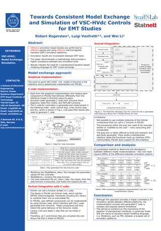
- 1. CONTACT INFORMATION Towards Consistent Model Exchange and Simulation of VSC-HVdc Controls for EMT Studies Robert Rogersten¹, Luigi Vanfretti¹², and Wei Li¹ KEYWORDS: VSC-HVDC; Model Exchange; Simulation. • Different simulation-based studies are performed by different parties and using different electromagnetic transient (EMT) simulation platforms. • Simulation results are inconsistent between EMT tools. • This paper demonstrates a methodology that provides a higher consistency between two simulation tools. • Results indicate the need for a standardized equation-based modeling language for EMT model exchange. Abstract: Conclusion: • Although this approach provides a higher consistency of simulation results between different platforms, the implementation process with generated C code is complex and exposes several limitations. • This serves as evidence on the importance of the adoption of standardized interfaces, in particular those that are native to equation-based modeling language (i.e. Modelica), such as FMI, between a broader set of simulation platforms CONTACTS: 1.School of Electrical Engineering Electric Power Systems Department KTH Royal Institute of Technology Teknikringen 33 100 44 Stockholm -SE Email: rrog@kth.se Email: luigiv@kth.se Email: wei3@kth.se 2.Statnett SF, R & D, Oslo, Norway E-mail: luigi.vanfretti@statnett.no Test systems: • Fortran can call a function written in C code. • The blocks in PSCAD are Fortran code, which call the EMTDC (Electromagnetic Transients including DC) library to combine them into an executable file. • In PSCAD, user defined components can be implemented by using Fortran code, which interface with the C code generated from Simulink. These components will thus inherit the same behavior of the Simulink model. • Library (.lib) and object (.obj) files can be linked in PSCAD. • Therefore, all C and Fortran files are compiled into one library file that is linked to PSCAD. Figure 2: The flowchart describes how the control.lib file is generated and linked as a library file in PSCAD during run-time. Limitations: • Not possible to use multiple instances of the Fortran components that can call a C function in PSCAD. • The procedures within the grey box need to be manually written or modified by the user--- time consuming and complicated. • The grey box is rather difficult to build and maintain and also lacks generality. There exists a standardized interface called the functional mock-up interface (FMI). Unfortunately, PSCAD lacks support for this interface. Comparison and analysis: The point-to-point VSC-HVDC link model in Simulink is the reference and is pedantically implemented into PSCAD. Graphical implementation: C code implementation: • Start from the graphical implementation and replace each component in PSCAD that behaves differently from the reference model in Simulink piece-by-piece. • Simulink Coder generates C code from Simulink block diagrams, state flow charts, and MATLAB functions. • The C code for controllers is generated and implemented in the following order: outer control loop, inner control loop, and PLL, which is shown in Fig.1. Low-pass filter blocks also need to generate C code. Table1: Files generated from the Simulink coder • Modifying the ModelName_data.c file changes the parameter values for the controller. • ModelName.c contains the step function. • The main execution file ert_main.c sets the inputs, then the step function is executed, and finally the outputs are set. Fortran Integration with C code: Overall Integration: Figure 1: Steps for Code Generation Model exchange approach: A quantitative method to determine the discrepancy between different model implementations---the root mean square (RMS) of the difference between simulation outputs Table2: RMS comparison of graphical implementation (up) and C code implementation (down)