SlideShare a Scribd company logo
1 of 19
Download to read offline
Power transformer maintenance. Field
Testing.
Andrés Tabernero García
Hardware Project Manager
Unitronics, S.A.
andres@unitronics.es
www.unitronics.es
Introduction
The politic change in some companies had a great influence in maintenance and
operation works in their electric machines. Those, have seen many times a decrease in
maintenance works allowing a cost decrease in a short term but generating a greater
risk of use of them in a mean and long term. The operating conditions also have
changed in the sense of taking the maximum advantage of each machine making it
work at the maximum possible ratings and some times above nominal values. This
situation trends to premature age the machine fleet and if those are not part of a
minimum maintenance program detecting risk situations or load limitation, the
resultant situation will lead in a mean time to an irregular manoeuvre field
(breakdowns, forced outages, supply interruptions…) that today are so usual and
negative to the end customer.
FIG 1. Breakdown of the dielectric system in a power transformer column. Courtesy from Electric Works Molina, Córdoba.
2
Power transformer is an electric machine with a useful life cycle of some 30 years. This
doesn’t mean to say that cannot be used above this time, in fact, a great part of the
electric and industrial fleet is being operated with reliable machines above this time.
The really important fact is to know the status and evolution of the transformer to be
in conditions to operate it with the maximum security and know if it is appropriate to
continue it’s use, know overload capacity, limit load, refurbish it or either take it out
from active service.
There is a group of maintenance techniques that from an electric point of view and
through some field tests are going to allow us to trace the transformer status as
indicated and in the case of breakdown diligently detect the real problem and perform
the required actions.
FIG 2. Field testing of a power transformer before putting into service (50MVA).
POWER TRANSFORMERS FIELD TESTING.
As a result of the owner company, the importance of the machine and the outage
possibilities, it is necessary to perform on each transformer a fitted maintenance
program with a test protocol previously accorded. Next will be indicated a series of test
that can set up this program and that are something like a continuation of validation
tests performed when manufacturing the transformer but adapted to field testing.
We have to take under account that in the field, in transformer installations, is not
usually possible to have bulky equipments, what states certain limitations to field test
with respect to manufacturing ones.
Described tests are chosen from the commercially available ones, standardized and
usual into test programs.
3
MAGNETIC / ELECTRIC CIRCUIT TESTS.
Those will be performed wit portable instrumentation (easily transported in vehicle/test
van) of a series of measurements that allow obtaining base parameters from the
transformer. It will be studied the punctual status to perform a diagnose and
parameter trending values to perform scheduled works. All this tests are off-line.
Electric/Magnetic field testing:
 No-load test. Turns Ratio (TTR). Polarity, connection group y excitation
current.
 Load test (short circuit test, impedance measurement).
 Winding resistance.
 Frequency response analysis (FRA).
- No-load test. Turns Ration. Polarity, connection group and excitation
current.
This test usually known as “no load” test and involves inserting an alternating voltage
in the high voltage winding of the transformer in each of it’s phases with low voltage
side open. With the result values can be obtained basic parameters from the
transformer:
Transformer Turns Ratio (TTR): quotient between high voltage / low voltage. Must
match with protocol /nameplate values.
FIG 3. Monophase transformer turns ratio unit, from Megger Company, model TTR100.
In the power transformer with tap changer you will take advantage to make the
register of each position from it giving extra information on its status and that of the
On Line Tap Changer (OLTC). This measurement will directly inform of the existence of
shorts between turns.
4
FIG 4. Results of a turns ratio test determining a short circuit between turns at low voltage side. Diagnose software from ETP
system (TRR unit UM1B from UNITRONICS). Red and green phases over imposed, yellow separated.
Polarity / connection group. Connection group can also be checked with the previous
results and aided with voltage diphase between high / low voltage.
FIG 5. 3-phase Transformer Turns Ratio Meter Unit from UNITRONICS Company, model UM1B.
Excitation current. It’s the current flowing into the high voltage winding with the low
voltage side open. This current should be proportional to the No-load acceptance test
but with the difference resultant from the use of test voltages different from nominal
values.
5
FIG 6. Transformer Turns Ratio Meter Unit from Megger Company, model TTR.
It shouldn’t exist excessive deflection from values measured between phases and its
normal a slight difference (geometric) between extreme and central windings. It will
exist great changes when appear heat points, degradation in the magnetic package,
loose core or detached magnetic shunt.
- Load test (short circuit test, Impedance measurement).
This test usually known as “short circuit test” is based in the insertion of a
voltage in one winding (high voltage one) with the other winding short-circuited. This
test simulated the factory one but its not at all comparable in results because of not
flowing nominal values. It is usual to register nominal and extreme positions if the
transformer had an OLTC.
FIG 7. 3phase short circuit impedance unit from UNITRONICS company, model UM5B.
Short circuit voltage. This parameter usually expressed in % and identified in the
nameplate of the transformer is the extrapolated result from the test voltage to
6
nominal voltage and should be near the protocol /nameplate value from the
transformer. It’s change will indicate irregularities in the magnetic core, winding
displacement, short-circuits, mechanical deformations…
FIG 8. Results screen from a short circuit test (unit UM5B, UNITRONICS company) indicating changes in the geometric circuit.
- Winding Resistance.
With this test we search determinate the pure ohmic resistance from each phase
windings both in high and low voltage and it exist a tap changer in each position. What
in a first approach can be easy to measure, its not so, because it is necessary to make
flow relatively high currents to register the usual low resistance values µ/m/ with
the required precision. This currents must also flow through the equivalent inductances
of the transformer.
7
FIG 9. Results from a Winding resistance test showing a problem in the high voltage winding (system UM3B, UNITRONICS
Company).
The high inductive character of power transformers (Equivalent L and magnetic core)
implicates magnetization time and measurement stabilization should be taken under
account while determination the measurement end and give the results.
FIG 10. 3-phase winding resistance meter from UNITRONICS Company, model UM3B.
This has more relevance in high power transformers or from special designs or
configurations.
8
FIG 11. Detected fault in an OLTC from the previous test results.
Final results must be temperature normalized to get results comparable in time and
compose parameters must be converted into simple ones (this is, when measuring a
Wye and the measure was performed between phases without; should extract each
phase winding values separately). This test result must be comparable with factory
protocol and will give clear information on the winding status, the tap changer and
connections (slacking or heating).
- Frequency Response Analysis testing.
The main purpose of this test is to determinate the frequency response graph of the
equivalent electric / dielectric / magnetic / mechanic altogether evaluated. There are
two approaches to this test:
Frequency sweep technique. A low voltage sweep generator is used synchronized with
a level meter that for each phase register a frequency response plot. The result is a
graph that correlates frequencies in horizontal axis and attenuations per phase in
vertical axis.
Pulse technique. A fast pulse of ~500V is given to the transformer and taken both at
the input and output in each phase.
9
FIG 12. FRA “signature” of a test with a problem in transformer windings detected with FRAMIT system.
FIG 13. Collapsed winding photograph and loose connections in the previous test transformer.
Next and in the computer, are used digital signal processing techniques with
mathematic algorithms that change from time domain to frequency domain giving the
same results than from sweep technique..
Both techniques give as a result the “signature” of the transformer with the
inside information of the complete electric / dielectric / magnetic / mechanic status.
This test is very useful as a complement of the usual tests and can also check that no
10
alterations were derived from transportation, loose windings or displaced, problems in
the magnetic core, etc.
FIG 14. FRA unit from Starlogic Company , model FRAMIT, represented in Europe by UNITRONICS.
Diagnosis and trending
Each previous test results are changed into the different registered parameters from
the transformed that were previously programmed in the test protocol.
This parameters will be submitted to a criteria evaluation to the diagnosis
emission.
FIG 15. Lookup of the Expert Diagnosis Software for Power Transformer Evaluation ETPDiagHelp from UNITRONICS Company.
Diagnose criteria can change depending on the transformer, depending of the
companies, but it exist a minimum values, another normalized and other ones than
from an empiric approach conform Expert Diagnose Software that could be a failure
11
criteria interpretation. This software applications give an orientation of the machine
status, but must be the maintenance expert who with all the machine data indicates
end diagnosis and performs necessary actions: repair, continue operation, program
new test, recommend service limitation...
Another scope will come from the historic/trending of the transformer. The parameter’s
evolution could help detecting machine’s degradation speed and the new maintenance
exigencies.
FIG 16. Lookup of Trends Software ETPTrends, showing a fault in the regulator and a later repair (From UNITRONICS Company).
DIELECTRIC SYSTEM TESTS.
One of the operating key elements in the power transformer and the one determining
its remaining useful life is the dielectric. Dielectric could be split in: liquid dielectric
(usually mineral oil) in which we’ll have certain manipulation degree trough possible
treatments and solid dielectric (paper) in which our work is limited only to the external
indirect check of it’s status. As a function of the maintenance policy of the owner
company, the importance of the machine and the tolerable failure risk, its suitable to
perform on it tests with a previously accorded program and protocol. Maintenance
programs will give as a result a bigger knowledge of the status and availability of
transformers. In a long term, this will translate in a very important concept: “Extension
of the life of Power Transformers”.
In this section we will insist in the electric detection methods although we will also
comment that there are another focused to laboratory and related to oil sampling. The
object of this article is to state the knowledge of this tests both if performed in the
utilities as if contracted to extern facilities. Next are resumed the usual field test
performed on the power transformer dielectric system.
12
ELECTRIC TESTS TO THE DIELECTRIC CIRCUIT.
It is a group of test that with measuring electronic instrumentation that can give a
punctual status evaluation of the dielectric in the power transformer. We will describe
the most usual test. Again, all they will be off-line (transformer out of service) apart
from the indicated exceptions.
Dielectric circuit tests.
 Insulation Resistance and Polarization Index (IR, PI).
 Recovery voltage Measurement (RVM) and time constant.
 Capacitance, Dissipation (power) factor (tan δ) and insulation losses in dielectric
/ bushing.
 Partial Discharge (PD).
Oil sampling.
 Dielectric Strength.
 Moisture content.
 Dissolved Gases.
 Furnan Analysis.
- Insulation Resistance.
This test has been the most usual historically, being called to “megger” the transformer
(the term comes from the firm of the first Megger systems).
FIG 17. Insulation Resistance and Polarization Index system, Firm Megger, model BM25.
This test is performed on a measuring tester able to generate high continuous voltages
usually of 5000V that applied between both dielectric terminals of the power
transformer (one terminal to all the bushings joined in high voltage, the other to low
voltage and ground) allow evaluating the punctual dielectric status inside. The tester
has a high voltage tester operating from batteries or from the main. Measuring
13
principle is based in measuring current / voltage in a continuous way that evolves as
an answer to a voltage step.
FIG 18. Equivalent diagram of the dielectric circuit of a transformer. Ri is the insulation resistance, Cg the geometric capacitance
and the different Ra/Ca emulate the equivalent dielectric absorption circuit.
Insulation Resistance will be the quotient between voltage and current at the end of
minute 1 of the test (~Ri in figure 18). This parameter should be above a minimum
normalized value. It contains direct information from the dielectric system status in the
transformer, but is very influenced by temperature (and should be temperature
normalized / corrected). So, its usual another parameter named Polarization Index
(PI). To measure it, the test is extended from minute 1 to minute 10, being PI, the
quotient of currents in both time instants. This value is now independent from
temperature and should be comparable in consecutive tests.
Recovery Voltage Measurement (RVM).
Other approach to get a generic knowledge of the dielectric status inside the
transformer (paper-oil) is with recovery voltage testing. With this test is obtained the
polarization spectrum of the dielectric mixing information both of dissolved humidity
and components degeneration.
Any dielectric can be simulated with an equivalent diagram as from figure 18.
Recovery voltage testing pursues determining “temporal spectrum” of the different
circuits Ra/Ca who include information of moisture/degradation in the dielectric.
Test is performed with the circuit from figure 19. It has several charge / discharge
steps of the dielectric from a continuous voltage source V whose result composes a
plot spectrum named polarization spectrum. Each point comes from a charge process
while a time T (S1 closed and S2 open) of the sample and discharges in a time T/2 (S1
open and S2 closed). Finally an electrometer (E= very high impedance voltmeter)
registers the point as the maximum of the recovery voltage curve given by the Ra/Ca.
14
FIG 19. Operation diagram of the recovery voltage meter (RVM).
The final plot (figure 20) follows the equivalent spectra of all the Ra/Ca related to the
circuit in figure 18. The appearance of the plot and the position of the maximum are
indicative of the final quality of the dielectric paper / oil. Greater moisture = bigger
deflection of the maximum to the left in the time axis.
FIG 20. Test screen from Unitronics RVM UM2B.
Test voltage has standardized in 2kV to be comparable and applicable to all power /
power / distribution oil submerged transformers. In figure 20 screen you can see in
horizontal axis cycle and in vertical axis maximum per cycle of recovery voltage. In
figure 21 system, apart from RVM test, includes in a time cycle greater than 10
minutes insulation resistance, polarization index and resistance evolution plot.
15
FIG 21. Unitronics Recovery Voltage Meter / RVM, model UM2B.
Capacitance / Tan delta ( Dissipation Factor) & dielectric losses /bushings).
Another usual approach when performing dielectric evaluation is tan delta. This test
uses AC and pursues to know loss angle of the tested element. This test system is
usually more bulky because in order to generate current enough in AC voltage its
necessary a greater power source. This measurement technique is again off-line
although there are systems that allow an on-line approach. This measurement includes
information of the moisture and contamination degree and emulates (greater voltage)
the behaviour and voltage aggressions similar to service ones. It is important to take
note of transformer temperature and environmental moisture (surface leakage).
FIG 22. Diagram of currents flowing through dielectric, IR resistive is in phase to voltage and capacitive IC out of phase 90º. Total
IT, defines δ angle and tangent.
16
FIG 23. Tan delta meter from Megger, model Delta 2000.
- Partial Discharge test.
It is possible to make partial discharge testing on power transformers, most of all on
the most powerful or critical units. Partial discharge are small discharges that appear
inside of the dielectric as a sign of its degeneration. They appear as a result of the
increase of the electric field in small gaseous voids inside the oil and also inside the
paper, epoxy or as a result of the presence of metallic contamination, etc. This
discharge accelerate the thermal degradation effects and though for the oil are auto-
regenerable, lead sometimes exponentially to the power transformer destruction.
There are two usual detection systems, acoustic and electric. Acoustic system seeks
sound mechanic manifestation (in ultrasonic range) of discharges even enabling eco-
location. Electric systems should allow determinate discharges and correlate them with
another parameters. This test can be made online or offline if a source apart is used to
energize the machine (difficult chance in field). In this test is important again to take
note of the temperature of the machine and environment conditions.
PHYSICAL – CHEMICAL TESTS.
Another important test group are those in which in the field you only extract
properly (see normative) an oil sample on/off line from which certain operating
characteristics of the transformer can be deduced.
- Breakdown voltage.
Oil degradation can be easily appreciated with this parameter tested. The test is based
in the insertion of electrodes immersed in oil of an increasing voltage up to when
discharge happens. Test is repeated six times to get a repeatable measurement. The
only disadvantage is that it is necessary to extract from the transformer a significant
sample (test cell will have 350...600ml). The report will include sample temperature.
17
FIG 24. Inside of the test vessel for breakdown voltage in oil of a Megger, model OTS60SX system. It can be seen discharge
terminals and agitation propeller.
- Moisture (Water content).
Until recently, dissolved moisture in oil was a relatively complex laboratory process.
Today, Megger company has got out to the marked a portable unit that close to easy
to locate reactives and minimal test care, can perform the test in field / plant /repair
shop in an easy and handy way. Implemented system is Karl-Fischer, the usual and
laboratory regulated but in a portable manner. It has good repeatability and accuracy.
It does only need a small oil sample (1ml) and the system executes the complete
control of the chemical process eliminating dissolved moisture and indicating quantity
in ppm, %...
FIG 25. System for moisture determination in oil, from Megger, Model KF875.
Another oil parameters.
Other usual laboratory test reporting complementary information of the oil /
transformer status are:
Power factor in liquids, interfacial tension, acid number, Oxidation Inhibitor, colour,
appearance, fire point, viscosity, PCB…
- Dissolved Gas Analysis & Ratios.
Oil dissolved gases testing started around 1956 in investigation from Buchholz relay
trigger in transformers. Some investigation of the gases generated there have created
18
specific normative that allow the interpretation of the possible problems inside the
transformer. Base parameters are both quantities of some generated gases as relative
proportions between gases and apparition / variation speed in taken samples. It can be
taken so indirect evidence of Partial Discharge, hot points, arcing, combustion, aging
and overheating, detecting incipient failures that could end the transformer life.
- Furan Analysis.
This laboratory test seeks determine the amount of some component (furaldehids) in
an insulating oil sample. Theory says that this kind of furanic derivates is never present
in oil in a natural way and will only exist as a sub product of paper degeneration inside
the transformer.
As a complement, we will indicate that exist treatments to decrease moisture and
purify the oil eliminating degradation products and taking away metallic particles, etc.
Anyway paper access is limited to the interface with oil, so transformer life is paper life.
Conclusions
From the short downtime available nowadays it is necessary to use test systems
that allow a maximum automation of tests to perform and conform a database with all
the test performed to can optimize diagnosis and trending.
It is also necessary to perform zero test either in installations or on new
machines: first to be certain the machine is in proper condition of use and fulfill
contractual requirements and second to have data available with which perform a later
predictive monitoring of faults.
Again we need the maintenance people to have a deep knowledge of this tests
and the way to perform them in order to get from them the maximum reliability either
if made by the own utility as from subcontracted to avoid weak. This tests though easy
and automatic, take with them some measurement details to take in account in order
the measurements to be reliable all this apart from the security details of the user.
FIG 26. Theoretical – practical formation in field testing on electric machines in UNITRONICS.
19
We have described most of the usual “standardized” test in measurement protocols.
With a short number of measuring elements we can have a clear idea of the complete
transformer status. Anyway, it is of a great importance to go more deeply in the
knowledge of this tests to insure their tracking both in the performance on our own or
subcontracted.
This test will be performed taking into account a series of precautions related both in
their normatives and in the experience logic. In all dielectric system tests, is important
to take note of transformer temperature and around conditions.
Its crucial that workers who make the test have an optimal formation in this kind of
testing, both making the tests as in diagnosis and trending.
References
1. IEC 60076-5:2000. Power transformers. Part 5: Ability to withstand short circuit.
2. IEC 60726:2003. Dry-type power transformers.
3. ANSI/IEEE Std 62-1995. IEEE Guide for Diagnostic Field Testing of Electric Power Apparatus-Part1:Oil Filled Power
Transformers, Regulators, and Reactors. IEEE Power Engineering Society-1995.
4. ANSI/IEEE Std C57.12.90-1993. IEEE Standard Test Code for Liquid-Immersed Distribution. Power and Regulating
Transformers and IEEE Guide for Short-Circuit Testing of Distribution and Power Transformers.
5. ANSI/IEEE Std. C57.12.00-1993. IEEE Standard General Requirements for Liquid-Immersed Distribution, Power and
Regulating Transformers.
6. EN 60156-1995. “Insulating liquids. Determination of the breakdown voltage at power frequency. Test method.”.
7. EN 60814-1997. “Insulating liquids. Oil-impregnated paper and pressboard. Determination of water by automatic coulometric
Karl Fischer Titration”.
8. EN 60567-1992. “Guide for the sampling of gases and of oil from oil-filled electrical equipment and for the analysis of free and
dissolved gases” .
9. EN 60599:1999. “Mineral oil-impregnated electrical equipment in service – Guide to the interpretation of dissolved and free
gases analysis.”.
10. EN 61620:1999. “Insulating liquids. Determination of the dielectric dissipation factor by measurement of the conductance and
capacitance. Test method.
11. EN 61198:1994. “Mineral insulating oils. Method for the determination of 2-furfural and related compounds”.

More Related Content

What's hot

TRANSFORMER TEST acceptance criteria
TRANSFORMER TEST acceptance criteriaTRANSFORMER TEST acceptance criteria
TRANSFORMER TEST acceptance criteriaRajuGupta88
 
Maintenance schedule of Substation.
Maintenance schedule of Substation.Maintenance schedule of Substation.
Maintenance schedule of Substation.Sheikh Nazmul Islam
 
Testing and Condition Monitoring of Substation Equipments
Testing and Condition Monitoring of Substation EquipmentsTesting and Condition Monitoring of Substation Equipments
Testing and Condition Monitoring of Substation EquipmentsSumeet Ratnawat
 
Commissioning of electrical equipments
Commissioning of electrical equipmentsCommissioning of electrical equipments
Commissioning of electrical equipmentsPalak Ariwala
 
Transformer maintenance
Transformer maintenance Transformer maintenance
Transformer maintenance Molla Morshad
 
Installation Operation & Maintenance of 33kV & 11kV Switchgear
Installation   Operation & Maintenance of 33kV & 11kV SwitchgearInstallation   Operation & Maintenance of 33kV & 11kV Switchgear
Installation Operation & Maintenance of 33kV & 11kV SwitchgearSheikh Nazmul Islam
 
TRANSFORMER SAMPLE REPORT DGA PHYSICAL CONDITION
TRANSFORMER SAMPLE REPORT DGA PHYSICAL CONDITION TRANSFORMER SAMPLE REPORT DGA PHYSICAL CONDITION
TRANSFORMER SAMPLE REPORT DGA PHYSICAL CONDITION RajuGupta88
 
OLTC Function Selection, Operation
OLTC Function Selection, OperationOLTC Function Selection, Operation
OLTC Function Selection, OperationMax Philipp
 
Line Differential - Test report for Alstom make Micom P546 relay
Line Differential - Test report for Alstom make Micom P546 relayLine Differential - Test report for Alstom make Micom P546 relay
Line Differential - Test report for Alstom make Micom P546 relaydavid roy
 
1 mrg000577 en_application_of_unit_protection_schemes_for_auto-transformers1
1 mrg000577 en_application_of_unit_protection_schemes_for_auto-transformers11 mrg000577 en_application_of_unit_protection_schemes_for_auto-transformers1
1 mrg000577 en_application_of_unit_protection_schemes_for_auto-transformers1NASSAR KALLIKETTIYAPURAKAL
 
Practical handbook-for-relay-protection-engineers
Practical handbook-for-relay-protection-engineersPractical handbook-for-relay-protection-engineers
Practical handbook-for-relay-protection-engineersSARAVANAN A
 
Tutorial on Distance and Over Current Protection
Tutorial on Distance and Over  Current ProtectionTutorial on Distance and Over  Current Protection
Tutorial on Distance and Over Current ProtectionSARAVANAN A
 
Power transformer manufacturing process and testing
Power transformer manufacturing process and testingPower transformer manufacturing process and testing
Power transformer manufacturing process and testingSai Kumar
 
Catalog for high voltage test equipment
Catalog for high voltage test equipmentCatalog for high voltage test equipment
Catalog for high voltage test equipmentkatherine feng
 

What's hot (20)

TRANSFORMER TEST acceptance criteria
TRANSFORMER TEST acceptance criteriaTRANSFORMER TEST acceptance criteria
TRANSFORMER TEST acceptance criteria
 
Maintenance schedule of Substation.
Maintenance schedule of Substation.Maintenance schedule of Substation.
Maintenance schedule of Substation.
 
Testing and Condition Monitoring of Substation Equipments
Testing and Condition Monitoring of Substation EquipmentsTesting and Condition Monitoring of Substation Equipments
Testing and Condition Monitoring of Substation Equipments
 
Commissioning of electrical equipments
Commissioning of electrical equipmentsCommissioning of electrical equipments
Commissioning of electrical equipments
 
Transformer maintenance
Transformer maintenance Transformer maintenance
Transformer maintenance
 
Installation Operation & Maintenance of 33kV & 11kV Switchgear
Installation   Operation & Maintenance of 33kV & 11kV SwitchgearInstallation   Operation & Maintenance of 33kV & 11kV Switchgear
Installation Operation & Maintenance of 33kV & 11kV Switchgear
 
TRANSFORMERS
TRANSFORMERSTRANSFORMERS
TRANSFORMERS
 
TRANSFORMER SAMPLE REPORT DGA PHYSICAL CONDITION
TRANSFORMER SAMPLE REPORT DGA PHYSICAL CONDITION TRANSFORMER SAMPLE REPORT DGA PHYSICAL CONDITION
TRANSFORMER SAMPLE REPORT DGA PHYSICAL CONDITION
 
OLTC Function Selection, Operation
OLTC Function Selection, OperationOLTC Function Selection, Operation
OLTC Function Selection, Operation
 
Line Differential - Test report for Alstom make Micom P546 relay
Line Differential - Test report for Alstom make Micom P546 relayLine Differential - Test report for Alstom make Micom P546 relay
Line Differential - Test report for Alstom make Micom P546 relay
 
1 mrg000577 en_application_of_unit_protection_schemes_for_auto-transformers1
1 mrg000577 en_application_of_unit_protection_schemes_for_auto-transformers11 mrg000577 en_application_of_unit_protection_schemes_for_auto-transformers1
1 mrg000577 en_application_of_unit_protection_schemes_for_auto-transformers1
 
EIT_Presentation
EIT_PresentationEIT_Presentation
EIT_Presentation
 
Transformers
TransformersTransformers
Transformers
 
Practical handbook-for-relay-protection-engineers
Practical handbook-for-relay-protection-engineersPractical handbook-for-relay-protection-engineers
Practical handbook-for-relay-protection-engineers
 
Tutorial on Distance and Over Current Protection
Tutorial on Distance and Over  Current ProtectionTutorial on Distance and Over  Current Protection
Tutorial on Distance and Over Current Protection
 
Substation commissioning1
Substation commissioning1Substation commissioning1
Substation commissioning1
 
Substation commissioning1
Substation commissioning1Substation commissioning1
Substation commissioning1
 
EIT_Presentation
EIT_PresentationEIT_Presentation
EIT_Presentation
 
Power transformer manufacturing process and testing
Power transformer manufacturing process and testingPower transformer manufacturing process and testing
Power transformer manufacturing process and testing
 
Catalog for high voltage test equipment
Catalog for high voltage test equipmentCatalog for high voltage test equipment
Catalog for high voltage test equipment
 

Similar to Power transformer maintenance

Dynamic Analysis and Testing of on-load tap changer
Dynamic Analysis and Testing of on-load tap changerDynamic Analysis and Testing of on-load tap changer
Dynamic Analysis and Testing of on-load tap changerLeonardo Nicolini
 
SMC ETP System Power Transformer Maintenance
SMC ETP System Power Transformer MaintenanceSMC ETP System Power Transformer Maintenance
SMC ETP System Power Transformer MaintenanceErika Herbozo
 
K.kufa meter test - c
K.kufa meter test - cK.kufa meter test - c
K.kufa meter test - cKumbirai Kufa
 
C0212014018
C0212014018C0212014018
C0212014018theijes
 
power quality improvement in distrution system using D statcom
power quality improvement in distrution system using D statcompower quality improvement in distrution system using D statcom
power quality improvement in distrution system using D statcom7867867869
 
Instrument Transformers - Following the Money: Best Practices in a Post AMI W...
Instrument Transformers - Following the Money: Best Practices in a Post AMI W...Instrument Transformers - Following the Money: Best Practices in a Post AMI W...
Instrument Transformers - Following the Money: Best Practices in a Post AMI W...TESCO - The Eastern Specialty Company
 
Electrical engineering-portal.com-mv circuit-breaker_or_vacuum_contactor_part_1
Electrical engineering-portal.com-mv circuit-breaker_or_vacuum_contactor_part_1Electrical engineering-portal.com-mv circuit-breaker_or_vacuum_contactor_part_1
Electrical engineering-portal.com-mv circuit-breaker_or_vacuum_contactor_part_1Abu Hashim
 
Enhanced Torque Control and Reduced Switching Frequency in Direct Torque Cont...
Enhanced Torque Control and Reduced Switching Frequency in Direct Torque Cont...Enhanced Torque Control and Reduced Switching Frequency in Direct Torque Cont...
Enhanced Torque Control and Reduced Switching Frequency in Direct Torque Cont...IJPEDS-IAES
 
Closed Loop Analysis of Multilevel Inverter Fed Drives 
Closed Loop Analysis of Multilevel Inverter Fed Drives Closed Loop Analysis of Multilevel Inverter Fed Drives 
Closed Loop Analysis of Multilevel Inverter Fed Drives IJPEDS-IAES
 
Short circuit current calculations
Short circuit current calculationsShort circuit current calculations
Short circuit current calculationsRonald Santos
 
A High-Performance SPWM Controller for Three-Phase UPS Systems Operating Unde...
A High-Performance SPWM Controller for Three-Phase UPS Systems Operating Unde...A High-Performance SPWM Controller for Three-Phase UPS Systems Operating Unde...
A High-Performance SPWM Controller for Three-Phase UPS Systems Operating Unde...ijiert bestjournal
 
IRJET- Study Over Current Relay (MCGG53) Response using Matlab Model
IRJET- Study Over Current Relay (MCGG53) Response using Matlab ModelIRJET- Study Over Current Relay (MCGG53) Response using Matlab Model
IRJET- Study Over Current Relay (MCGG53) Response using Matlab ModelIRJET Journal
 
Design consideration of an mmc hvdc system based on 4500 v:4000a emitter turn...
Design consideration of an mmc hvdc system based on 4500 v:4000a emitter turn...Design consideration of an mmc hvdc system based on 4500 v:4000a emitter turn...
Design consideration of an mmc hvdc system based on 4500 v:4000a emitter turn...Ghazal Falahi
 
project presentation on "THMC"
project presentation on "THMC"project presentation on "THMC"
project presentation on "THMC"Teja venkat
 
A Multilevel Inverter with MPPT Control for Drifting Analysis and Improved Po...
A Multilevel Inverter with MPPT Control for Drifting Analysis and Improved Po...A Multilevel Inverter with MPPT Control for Drifting Analysis and Improved Po...
A Multilevel Inverter with MPPT Control for Drifting Analysis and Improved Po...IRJET Journal
 
Performance Improvement with Model Predictive Torque Control of IM Drives usi...
Performance Improvement with Model Predictive Torque Control of IM Drives usi...Performance Improvement with Model Predictive Torque Control of IM Drives usi...
Performance Improvement with Model Predictive Torque Control of IM Drives usi...IRJET Journal
 
Emc model for modern power electronic systems for
Emc model for modern power electronic systems forEmc model for modern power electronic systems for
Emc model for modern power electronic systems foreSAT Publishing House
 

Similar to Power transformer maintenance (20)

Art%20 e sierra%20etp%20mantenimiento
Art%20 e sierra%20etp%20mantenimientoArt%20 e sierra%20etp%20mantenimiento
Art%20 e sierra%20etp%20mantenimiento
 
Dynamic Analysis and Testing of on-load tap changer
Dynamic Analysis and Testing of on-load tap changerDynamic Analysis and Testing of on-load tap changer
Dynamic Analysis and Testing of on-load tap changer
 
SMC ETP System Power Transformer Maintenance
SMC ETP System Power Transformer MaintenanceSMC ETP System Power Transformer Maintenance
SMC ETP System Power Transformer Maintenance
 
K.kufa meter test - c
K.kufa meter test - cK.kufa meter test - c
K.kufa meter test - c
 
C0212014018
C0212014018C0212014018
C0212014018
 
power quality improvement in distrution system using D statcom
power quality improvement in distrution system using D statcompower quality improvement in distrution system using D statcom
power quality improvement in distrution system using D statcom
 
Bb4103331337
Bb4103331337Bb4103331337
Bb4103331337
 
Instrument Transformers - Following the Money: Best Practices in a Post AMI W...
Instrument Transformers - Following the Money: Best Practices in a Post AMI W...Instrument Transformers - Following the Money: Best Practices in a Post AMI W...
Instrument Transformers - Following the Money: Best Practices in a Post AMI W...
 
Electrical engineering-portal.com-mv circuit-breaker_or_vacuum_contactor_part_1
Electrical engineering-portal.com-mv circuit-breaker_or_vacuum_contactor_part_1Electrical engineering-portal.com-mv circuit-breaker_or_vacuum_contactor_part_1
Electrical engineering-portal.com-mv circuit-breaker_or_vacuum_contactor_part_1
 
Enhanced Torque Control and Reduced Switching Frequency in Direct Torque Cont...
Enhanced Torque Control and Reduced Switching Frequency in Direct Torque Cont...Enhanced Torque Control and Reduced Switching Frequency in Direct Torque Cont...
Enhanced Torque Control and Reduced Switching Frequency in Direct Torque Cont...
 
Closed Loop Analysis of Multilevel Inverter Fed Drives 
Closed Loop Analysis of Multilevel Inverter Fed Drives Closed Loop Analysis of Multilevel Inverter Fed Drives 
Closed Loop Analysis of Multilevel Inverter Fed Drives 
 
Short circuit current calculations
Short circuit current calculationsShort circuit current calculations
Short circuit current calculations
 
A High-Performance SPWM Controller for Three-Phase UPS Systems Operating Unde...
A High-Performance SPWM Controller for Three-Phase UPS Systems Operating Unde...A High-Performance SPWM Controller for Three-Phase UPS Systems Operating Unde...
A High-Performance SPWM Controller for Three-Phase UPS Systems Operating Unde...
 
IRJET- Study Over Current Relay (MCGG53) Response using Matlab Model
IRJET- Study Over Current Relay (MCGG53) Response using Matlab ModelIRJET- Study Over Current Relay (MCGG53) Response using Matlab Model
IRJET- Study Over Current Relay (MCGG53) Response using Matlab Model
 
Design consideration of an mmc hvdc system based on 4500 v:4000a emitter turn...
Design consideration of an mmc hvdc system based on 4500 v:4000a emitter turn...Design consideration of an mmc hvdc system based on 4500 v:4000a emitter turn...
Design consideration of an mmc hvdc system based on 4500 v:4000a emitter turn...
 
project presentation on "THMC"
project presentation on "THMC"project presentation on "THMC"
project presentation on "THMC"
 
A Multilevel Inverter with MPPT Control for Drifting Analysis and Improved Po...
A Multilevel Inverter with MPPT Control for Drifting Analysis and Improved Po...A Multilevel Inverter with MPPT Control for Drifting Analysis and Improved Po...
A Multilevel Inverter with MPPT Control for Drifting Analysis and Improved Po...
 
Performance Improvement with Model Predictive Torque Control of IM Drives usi...
Performance Improvement with Model Predictive Torque Control of IM Drives usi...Performance Improvement with Model Predictive Torque Control of IM Drives usi...
Performance Improvement with Model Predictive Torque Control of IM Drives usi...
 
Solid-State Transformer (S2T) of Single Phase Matrix Converter
Solid-State Transformer (S2T) of Single Phase Matrix ConverterSolid-State Transformer (S2T) of Single Phase Matrix Converter
Solid-State Transformer (S2T) of Single Phase Matrix Converter
 
Emc model for modern power electronic systems for
Emc model for modern power electronic systems forEmc model for modern power electronic systems for
Emc model for modern power electronic systems for
 

More from Luis Antonio González Mederos

Da handbook section_3_power_distribution_systems_757959_ena
Da handbook section_3_power_distribution_systems_757959_enaDa handbook section_3_power_distribution_systems_757959_ena
Da handbook section_3_power_distribution_systems_757959_enaLuis Antonio González Mederos
 
Da handbook section_3_power_distribution_systems_757959_ena
Da handbook section_3_power_distribution_systems_757959_enaDa handbook section_3_power_distribution_systems_757959_ena
Da handbook section_3_power_distribution_systems_757959_enaLuis Antonio González Mederos
 
{A1fad7c7 d7c8-4772-8e67-3a934e1341ca} wp027007-en_fin_oct2016
{A1fad7c7 d7c8-4772-8e67-3a934e1341ca} wp027007-en_fin_oct2016{A1fad7c7 d7c8-4772-8e67-3a934e1341ca} wp027007-en_fin_oct2016
{A1fad7c7 d7c8-4772-8e67-3a934e1341ca} wp027007-en_fin_oct2016Luis Antonio González Mederos
 
{76d7e191 801e-4032-8c0f-2e0e374a94fc} short-circuit_current_rating_wp033001_en
{76d7e191 801e-4032-8c0f-2e0e374a94fc} short-circuit_current_rating_wp033001_en{76d7e191 801e-4032-8c0f-2e0e374a94fc} short-circuit_current_rating_wp033001_en
{76d7e191 801e-4032-8c0f-2e0e374a94fc} short-circuit_current_rating_wp033001_enLuis Antonio González Mederos
 
{14dfe281 5214-4c9d-ae78-8fb4fe0a2c62} wp042001en-final_nov2014
{14dfe281 5214-4c9d-ae78-8fb4fe0a2c62} wp042001en-final_nov2014{14dfe281 5214-4c9d-ae78-8fb4fe0a2c62} wp042001en-final_nov2014
{14dfe281 5214-4c9d-ae78-8fb4fe0a2c62} wp042001en-final_nov2014Luis Antonio González Mederos
 
{0db3438a 3954-4fd2-8dea-8af7191aa256} motor-starter_for_usa_and_canada_39200...
{0db3438a 3954-4fd2-8dea-8af7191aa256} motor-starter_for_usa_and_canada_39200...{0db3438a 3954-4fd2-8dea-8af7191aa256} motor-starter_for_usa_and_canada_39200...
{0db3438a 3954-4fd2-8dea-8af7191aa256} motor-starter_for_usa_and_canada_39200...Luis Antonio González Mederos
 
Abb surge arresters product overview 1 hc0075750 ad en
Abb surge arresters   product overview 1 hc0075750 ad enAbb surge arresters   product overview 1 hc0075750 ad en
Abb surge arresters product overview 1 hc0075750 ad enLuis Antonio González Mederos
 

More from Luis Antonio González Mederos (20)

Rej603 pg 1_mdb07217-yn_e_ne
Rej603 pg 1_mdb07217-yn_e_neRej603 pg 1_mdb07217-yn_e_ne
Rej603 pg 1_mdb07217-yn_e_ne
 
Da handbook section_3_power_distribution_systems_757959_ena
Da handbook section_3_power_distribution_systems_757959_enaDa handbook section_3_power_distribution_systems_757959_ena
Da handbook section_3_power_distribution_systems_757959_ena
 
Gymr motor starting_solutions
Gymr motor starting_solutionsGymr motor starting_solutions
Gymr motor starting_solutions
 
Zone concept broch_756780_lre_na
Zone concept broch_756780_lre_naZone concept broch_756780_lre_na
Zone concept broch_756780_lre_na
 
Da handbook section_3_power_distribution_systems_757959_ena
Da handbook section_3_power_distribution_systems_757959_enaDa handbook section_3_power_distribution_systems_757959_ena
Da handbook section_3_power_distribution_systems_757959_ena
 
E1 a
E1 aE1 a
E1 a
 
Abb white paper_dtc_motor_es_3aua000019548
Abb white paper_dtc_motor_es_3aua000019548Abb white paper_dtc_motor_es_3aua000019548
Abb white paper_dtc_motor_es_3aua000019548
 
Abb white paper_dtc_a4_20150414
Abb white paper_dtc_a4_20150414Abb white paper_dtc_a4_20150414
Abb white paper_dtc_a4_20150414
 
Abb softstartery pstx kat_en15
Abb softstartery pstx kat_en15Abb softstartery pstx kat_en15
Abb softstartery pstx kat_en15
 
{A1fad7c7 d7c8-4772-8e67-3a934e1341ca} wp027007-en_fin_oct2016
{A1fad7c7 d7c8-4772-8e67-3a934e1341ca} wp027007-en_fin_oct2016{A1fad7c7 d7c8-4772-8e67-3a934e1341ca} wp027007-en_fin_oct2016
{A1fad7c7 d7c8-4772-8e67-3a934e1341ca} wp027007-en_fin_oct2016
 
{76d7e191 801e-4032-8c0f-2e0e374a94fc} short-circuit_current_rating_wp033001_en
{76d7e191 801e-4032-8c0f-2e0e374a94fc} short-circuit_current_rating_wp033001_en{76d7e191 801e-4032-8c0f-2e0e374a94fc} short-circuit_current_rating_wp033001_en
{76d7e191 801e-4032-8c0f-2e0e374a94fc} short-circuit_current_rating_wp033001_en
 
{14dfe281 5214-4c9d-ae78-8fb4fe0a2c62} wp042001en-final_nov2014
{14dfe281 5214-4c9d-ae78-8fb4fe0a2c62} wp042001en-final_nov2014{14dfe281 5214-4c9d-ae78-8fb4fe0a2c62} wp042001en-final_nov2014
{14dfe281 5214-4c9d-ae78-8fb4fe0a2c62} wp042001en-final_nov2014
 
{0db3438a 3954-4fd2-8dea-8af7191aa256} motor-starter_for_usa_and_canada_39200...
{0db3438a 3954-4fd2-8dea-8af7191aa256} motor-starter_for_usa_and_canada_39200...{0db3438a 3954-4fd2-8dea-8af7191aa256} motor-starter_for_usa_and_canada_39200...
{0db3438a 3954-4fd2-8dea-8af7191aa256} motor-starter_for_usa_and_canada_39200...
 
Abb surge arresters product overview 1 hc0075750 ad en
Abb surge arresters   product overview 1 hc0075750 ad enAbb surge arresters   product overview 1 hc0075750 ad en
Abb surge arresters product overview 1 hc0075750 ad en
 
Abb lv breakers working with trip curves
Abb lv breakers working with trip curvesAbb lv breakers working with trip curves
Abb lv breakers working with trip curves
 
Abb b.g. controlled switching ed4
Abb b.g. controlled switching ed4Abb b.g. controlled switching ed4
Abb b.g. controlled switching ed4
 
Oil testing cat 2003 149-v02
Oil testing cat 2003 149-v02Oil testing cat 2003 149-v02
Oil testing cat 2003 149-v02
 
Motor phase tester_ug_en_v01
Motor phase tester_ug_en_v01Motor phase tester_ug_en_v01
Motor phase tester_ug_en_v01
 
Nafta power catalog_sc_en_v01
Nafta power catalog_sc_en_v01Nafta power catalog_sc_en_v01
Nafta power catalog_sc_en_v01
 
High voltagebooklet ug_en_v01
High voltagebooklet ug_en_v01High voltagebooklet ug_en_v01
High voltagebooklet ug_en_v01
 

Recently uploaded

Sachpazis Costas: Geotechnical Engineering: A student's Perspective Introduction
Sachpazis Costas: Geotechnical Engineering: A student's Perspective IntroductionSachpazis Costas: Geotechnical Engineering: A student's Perspective Introduction
Sachpazis Costas: Geotechnical Engineering: A student's Perspective IntroductionDr.Costas Sachpazis
 
ZXCTN 5804 / ZTE PTN / ZTE POTN / ZTE 5804 PTN / ZTE POTN 5804 ( 100/200 GE Z...
ZXCTN 5804 / ZTE PTN / ZTE POTN / ZTE 5804 PTN / ZTE POTN 5804 ( 100/200 GE Z...ZXCTN 5804 / ZTE PTN / ZTE POTN / ZTE 5804 PTN / ZTE POTN 5804 ( 100/200 GE Z...
ZXCTN 5804 / ZTE PTN / ZTE POTN / ZTE 5804 PTN / ZTE POTN 5804 ( 100/200 GE Z...ZTE
 
Architect Hassan Khalil Portfolio for 2024
Architect Hassan Khalil Portfolio for 2024Architect Hassan Khalil Portfolio for 2024
Architect Hassan Khalil Portfolio for 2024hassan khalil
 
main PPT.pptx of girls hostel security using rfid
main PPT.pptx of girls hostel security using rfidmain PPT.pptx of girls hostel security using rfid
main PPT.pptx of girls hostel security using rfidNikhilNagaraju
 
Study on Air-Water & Water-Water Heat Exchange in a Finned Tube Exchanger
Study on Air-Water & Water-Water Heat Exchange in a Finned Tube ExchangerStudy on Air-Water & Water-Water Heat Exchange in a Finned Tube Exchanger
Study on Air-Water & Water-Water Heat Exchange in a Finned Tube ExchangerAnamika Sarkar
 
HARMONY IN THE HUMAN BEING - Unit-II UHV-2
HARMONY IN THE HUMAN BEING - Unit-II UHV-2HARMONY IN THE HUMAN BEING - Unit-II UHV-2
HARMONY IN THE HUMAN BEING - Unit-II UHV-2RajaP95
 
CCS355 Neural Network & Deep Learning Unit II Notes with Question bank .pdf
CCS355 Neural Network & Deep Learning Unit II Notes with Question bank .pdfCCS355 Neural Network & Deep Learning Unit II Notes with Question bank .pdf
CCS355 Neural Network & Deep Learning Unit II Notes with Question bank .pdfAsst.prof M.Gokilavani
 
IVE Industry Focused Event - Defence Sector 2024
IVE Industry Focused Event - Defence Sector 2024IVE Industry Focused Event - Defence Sector 2024
IVE Industry Focused Event - Defence Sector 2024Mark Billinghurst
 
Past, Present and Future of Generative AI
Past, Present and Future of Generative AIPast, Present and Future of Generative AI
Past, Present and Future of Generative AIabhishek36461
 
Gfe Mayur Vihar Call Girls Service WhatsApp -> 9999965857 Available 24x7 ^ De...
Gfe Mayur Vihar Call Girls Service WhatsApp -> 9999965857 Available 24x7 ^ De...Gfe Mayur Vihar Call Girls Service WhatsApp -> 9999965857 Available 24x7 ^ De...
Gfe Mayur Vihar Call Girls Service WhatsApp -> 9999965857 Available 24x7 ^ De...srsj9000
 
APPLICATIONS-AC/DC DRIVES-OPERATING CHARACTERISTICS
APPLICATIONS-AC/DC DRIVES-OPERATING CHARACTERISTICSAPPLICATIONS-AC/DC DRIVES-OPERATING CHARACTERISTICS
APPLICATIONS-AC/DC DRIVES-OPERATING CHARACTERISTICSKurinjimalarL3
 
(ANVI) Koregaon Park Call Girls Just Call 7001035870 [ Cash on Delivery ] Pun...
(ANVI) Koregaon Park Call Girls Just Call 7001035870 [ Cash on Delivery ] Pun...(ANVI) Koregaon Park Call Girls Just Call 7001035870 [ Cash on Delivery ] Pun...
(ANVI) Koregaon Park Call Girls Just Call 7001035870 [ Cash on Delivery ] Pun...ranjana rawat
 
Internship report on mechanical engineering
Internship report on mechanical engineeringInternship report on mechanical engineering
Internship report on mechanical engineeringmalavadedarshan25
 
Biology for Computer Engineers Course Handout.pptx
Biology for Computer Engineers Course Handout.pptxBiology for Computer Engineers Course Handout.pptx
Biology for Computer Engineers Course Handout.pptxDeepakSakkari2
 
CCS355 Neural Network & Deep Learning UNIT III notes and Question bank .pdf
CCS355 Neural Network & Deep Learning UNIT III notes and Question bank .pdfCCS355 Neural Network & Deep Learning UNIT III notes and Question bank .pdf
CCS355 Neural Network & Deep Learning UNIT III notes and Question bank .pdfAsst.prof M.Gokilavani
 
Introduction to Microprocesso programming and interfacing.pptx
Introduction to Microprocesso programming and interfacing.pptxIntroduction to Microprocesso programming and interfacing.pptx
Introduction to Microprocesso programming and interfacing.pptxvipinkmenon1
 
Decoding Kotlin - Your guide to solving the mysterious in Kotlin.pptx
Decoding Kotlin - Your guide to solving the mysterious in Kotlin.pptxDecoding Kotlin - Your guide to solving the mysterious in Kotlin.pptx
Decoding Kotlin - Your guide to solving the mysterious in Kotlin.pptxJoão Esperancinha
 
HARMONY IN THE NATURE AND EXISTENCE - Unit-IV
HARMONY IN THE NATURE AND EXISTENCE - Unit-IVHARMONY IN THE NATURE AND EXISTENCE - Unit-IV
HARMONY IN THE NATURE AND EXISTENCE - Unit-IVRajaP95
 

Recently uploaded (20)

Sachpazis Costas: Geotechnical Engineering: A student's Perspective Introduction
Sachpazis Costas: Geotechnical Engineering: A student's Perspective IntroductionSachpazis Costas: Geotechnical Engineering: A student's Perspective Introduction
Sachpazis Costas: Geotechnical Engineering: A student's Perspective Introduction
 
ZXCTN 5804 / ZTE PTN / ZTE POTN / ZTE 5804 PTN / ZTE POTN 5804 ( 100/200 GE Z...
ZXCTN 5804 / ZTE PTN / ZTE POTN / ZTE 5804 PTN / ZTE POTN 5804 ( 100/200 GE Z...ZXCTN 5804 / ZTE PTN / ZTE POTN / ZTE 5804 PTN / ZTE POTN 5804 ( 100/200 GE Z...
ZXCTN 5804 / ZTE PTN / ZTE POTN / ZTE 5804 PTN / ZTE POTN 5804 ( 100/200 GE Z...
 
Architect Hassan Khalil Portfolio for 2024
Architect Hassan Khalil Portfolio for 2024Architect Hassan Khalil Portfolio for 2024
Architect Hassan Khalil Portfolio for 2024
 
main PPT.pptx of girls hostel security using rfid
main PPT.pptx of girls hostel security using rfidmain PPT.pptx of girls hostel security using rfid
main PPT.pptx of girls hostel security using rfid
 
Study on Air-Water & Water-Water Heat Exchange in a Finned Tube Exchanger
Study on Air-Water & Water-Water Heat Exchange in a Finned Tube ExchangerStudy on Air-Water & Water-Water Heat Exchange in a Finned Tube Exchanger
Study on Air-Water & Water-Water Heat Exchange in a Finned Tube Exchanger
 
HARMONY IN THE HUMAN BEING - Unit-II UHV-2
HARMONY IN THE HUMAN BEING - Unit-II UHV-2HARMONY IN THE HUMAN BEING - Unit-II UHV-2
HARMONY IN THE HUMAN BEING - Unit-II UHV-2
 
CCS355 Neural Network & Deep Learning Unit II Notes with Question bank .pdf
CCS355 Neural Network & Deep Learning Unit II Notes with Question bank .pdfCCS355 Neural Network & Deep Learning Unit II Notes with Question bank .pdf
CCS355 Neural Network & Deep Learning Unit II Notes with Question bank .pdf
 
IVE Industry Focused Event - Defence Sector 2024
IVE Industry Focused Event - Defence Sector 2024IVE Industry Focused Event - Defence Sector 2024
IVE Industry Focused Event - Defence Sector 2024
 
Past, Present and Future of Generative AI
Past, Present and Future of Generative AIPast, Present and Future of Generative AI
Past, Present and Future of Generative AI
 
9953056974 Call Girls In South Ex, Escorts (Delhi) NCR.pdf
9953056974 Call Girls In South Ex, Escorts (Delhi) NCR.pdf9953056974 Call Girls In South Ex, Escorts (Delhi) NCR.pdf
9953056974 Call Girls In South Ex, Escorts (Delhi) NCR.pdf
 
Gfe Mayur Vihar Call Girls Service WhatsApp -> 9999965857 Available 24x7 ^ De...
Gfe Mayur Vihar Call Girls Service WhatsApp -> 9999965857 Available 24x7 ^ De...Gfe Mayur Vihar Call Girls Service WhatsApp -> 9999965857 Available 24x7 ^ De...
Gfe Mayur Vihar Call Girls Service WhatsApp -> 9999965857 Available 24x7 ^ De...
 
APPLICATIONS-AC/DC DRIVES-OPERATING CHARACTERISTICS
APPLICATIONS-AC/DC DRIVES-OPERATING CHARACTERISTICSAPPLICATIONS-AC/DC DRIVES-OPERATING CHARACTERISTICS
APPLICATIONS-AC/DC DRIVES-OPERATING CHARACTERISTICS
 
(ANVI) Koregaon Park Call Girls Just Call 7001035870 [ Cash on Delivery ] Pun...
(ANVI) Koregaon Park Call Girls Just Call 7001035870 [ Cash on Delivery ] Pun...(ANVI) Koregaon Park Call Girls Just Call 7001035870 [ Cash on Delivery ] Pun...
(ANVI) Koregaon Park Call Girls Just Call 7001035870 [ Cash on Delivery ] Pun...
 
Call Us -/9953056974- Call Girls In Vikaspuri-/- Delhi NCR
Call Us -/9953056974- Call Girls In Vikaspuri-/- Delhi NCRCall Us -/9953056974- Call Girls In Vikaspuri-/- Delhi NCR
Call Us -/9953056974- Call Girls In Vikaspuri-/- Delhi NCR
 
Internship report on mechanical engineering
Internship report on mechanical engineeringInternship report on mechanical engineering
Internship report on mechanical engineering
 
Biology for Computer Engineers Course Handout.pptx
Biology for Computer Engineers Course Handout.pptxBiology for Computer Engineers Course Handout.pptx
Biology for Computer Engineers Course Handout.pptx
 
CCS355 Neural Network & Deep Learning UNIT III notes and Question bank .pdf
CCS355 Neural Network & Deep Learning UNIT III notes and Question bank .pdfCCS355 Neural Network & Deep Learning UNIT III notes and Question bank .pdf
CCS355 Neural Network & Deep Learning UNIT III notes and Question bank .pdf
 
Introduction to Microprocesso programming and interfacing.pptx
Introduction to Microprocesso programming and interfacing.pptxIntroduction to Microprocesso programming and interfacing.pptx
Introduction to Microprocesso programming and interfacing.pptx
 
Decoding Kotlin - Your guide to solving the mysterious in Kotlin.pptx
Decoding Kotlin - Your guide to solving the mysterious in Kotlin.pptxDecoding Kotlin - Your guide to solving the mysterious in Kotlin.pptx
Decoding Kotlin - Your guide to solving the mysterious in Kotlin.pptx
 
HARMONY IN THE NATURE AND EXISTENCE - Unit-IV
HARMONY IN THE NATURE AND EXISTENCE - Unit-IVHARMONY IN THE NATURE AND EXISTENCE - Unit-IV
HARMONY IN THE NATURE AND EXISTENCE - Unit-IV
 

Power transformer maintenance

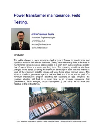
  • 1. Power transformer maintenance. Field Testing. Andrés Tabernero García Hardware Project Manager Unitronics, S.A. andres@unitronics.es www.unitronics.es Introduction The politic change in some companies had a great influence in maintenance and operation works in their electric machines. Those, have seen many times a decrease in maintenance works allowing a cost decrease in a short term but generating a greater risk of use of them in a mean and long term. The operating conditions also have changed in the sense of taking the maximum advantage of each machine making it work at the maximum possible ratings and some times above nominal values. This situation trends to premature age the machine fleet and if those are not part of a minimum maintenance program detecting risk situations or load limitation, the resultant situation will lead in a mean time to an irregular manoeuvre field (breakdowns, forced outages, supply interruptions…) that today are so usual and negative to the end customer. FIG 1. Breakdown of the dielectric system in a power transformer column. Courtesy from Electric Works Molina, Córdoba.
  • 2. 2 Power transformer is an electric machine with a useful life cycle of some 30 years. This doesn’t mean to say that cannot be used above this time, in fact, a great part of the electric and industrial fleet is being operated with reliable machines above this time. The really important fact is to know the status and evolution of the transformer to be in conditions to operate it with the maximum security and know if it is appropriate to continue it’s use, know overload capacity, limit load, refurbish it or either take it out from active service. There is a group of maintenance techniques that from an electric point of view and through some field tests are going to allow us to trace the transformer status as indicated and in the case of breakdown diligently detect the real problem and perform the required actions. FIG 2. Field testing of a power transformer before putting into service (50MVA). POWER TRANSFORMERS FIELD TESTING. As a result of the owner company, the importance of the machine and the outage possibilities, it is necessary to perform on each transformer a fitted maintenance program with a test protocol previously accorded. Next will be indicated a series of test that can set up this program and that are something like a continuation of validation tests performed when manufacturing the transformer but adapted to field testing. We have to take under account that in the field, in transformer installations, is not usually possible to have bulky equipments, what states certain limitations to field test with respect to manufacturing ones. Described tests are chosen from the commercially available ones, standardized and usual into test programs.
  • 3. 3 MAGNETIC / ELECTRIC CIRCUIT TESTS. Those will be performed wit portable instrumentation (easily transported in vehicle/test van) of a series of measurements that allow obtaining base parameters from the transformer. It will be studied the punctual status to perform a diagnose and parameter trending values to perform scheduled works. All this tests are off-line. Electric/Magnetic field testing:  No-load test. Turns Ratio (TTR). Polarity, connection group y excitation current.  Load test (short circuit test, impedance measurement).  Winding resistance.  Frequency response analysis (FRA). - No-load test. Turns Ration. Polarity, connection group and excitation current. This test usually known as “no load” test and involves inserting an alternating voltage in the high voltage winding of the transformer in each of it’s phases with low voltage side open. With the result values can be obtained basic parameters from the transformer: Transformer Turns Ratio (TTR): quotient between high voltage / low voltage. Must match with protocol /nameplate values. FIG 3. Monophase transformer turns ratio unit, from Megger Company, model TTR100. In the power transformer with tap changer you will take advantage to make the register of each position from it giving extra information on its status and that of the On Line Tap Changer (OLTC). This measurement will directly inform of the existence of shorts between turns.
  • 4. 4 FIG 4. Results of a turns ratio test determining a short circuit between turns at low voltage side. Diagnose software from ETP system (TRR unit UM1B from UNITRONICS). Red and green phases over imposed, yellow separated. Polarity / connection group. Connection group can also be checked with the previous results and aided with voltage diphase between high / low voltage. FIG 5. 3-phase Transformer Turns Ratio Meter Unit from UNITRONICS Company, model UM1B. Excitation current. It’s the current flowing into the high voltage winding with the low voltage side open. This current should be proportional to the No-load acceptance test but with the difference resultant from the use of test voltages different from nominal values.
  • 5. 5 FIG 6. Transformer Turns Ratio Meter Unit from Megger Company, model TTR. It shouldn’t exist excessive deflection from values measured between phases and its normal a slight difference (geometric) between extreme and central windings. It will exist great changes when appear heat points, degradation in the magnetic package, loose core or detached magnetic shunt. - Load test (short circuit test, Impedance measurement). This test usually known as “short circuit test” is based in the insertion of a voltage in one winding (high voltage one) with the other winding short-circuited. This test simulated the factory one but its not at all comparable in results because of not flowing nominal values. It is usual to register nominal and extreme positions if the transformer had an OLTC. FIG 7. 3phase short circuit impedance unit from UNITRONICS company, model UM5B. Short circuit voltage. This parameter usually expressed in % and identified in the nameplate of the transformer is the extrapolated result from the test voltage to
  • 6. 6 nominal voltage and should be near the protocol /nameplate value from the transformer. It’s change will indicate irregularities in the magnetic core, winding displacement, short-circuits, mechanical deformations… FIG 8. Results screen from a short circuit test (unit UM5B, UNITRONICS company) indicating changes in the geometric circuit. - Winding Resistance. With this test we search determinate the pure ohmic resistance from each phase windings both in high and low voltage and it exist a tap changer in each position. What in a first approach can be easy to measure, its not so, because it is necessary to make flow relatively high currents to register the usual low resistance values µ/m/ with the required precision. This currents must also flow through the equivalent inductances of the transformer.
  • 7. 7 FIG 9. Results from a Winding resistance test showing a problem in the high voltage winding (system UM3B, UNITRONICS Company). The high inductive character of power transformers (Equivalent L and magnetic core) implicates magnetization time and measurement stabilization should be taken under account while determination the measurement end and give the results. FIG 10. 3-phase winding resistance meter from UNITRONICS Company, model UM3B. This has more relevance in high power transformers or from special designs or configurations.
  • 8. 8 FIG 11. Detected fault in an OLTC from the previous test results. Final results must be temperature normalized to get results comparable in time and compose parameters must be converted into simple ones (this is, when measuring a Wye and the measure was performed between phases without; should extract each phase winding values separately). This test result must be comparable with factory protocol and will give clear information on the winding status, the tap changer and connections (slacking or heating). - Frequency Response Analysis testing. The main purpose of this test is to determinate the frequency response graph of the equivalent electric / dielectric / magnetic / mechanic altogether evaluated. There are two approaches to this test: Frequency sweep technique. A low voltage sweep generator is used synchronized with a level meter that for each phase register a frequency response plot. The result is a graph that correlates frequencies in horizontal axis and attenuations per phase in vertical axis. Pulse technique. A fast pulse of ~500V is given to the transformer and taken both at the input and output in each phase.
  • 9. 9 FIG 12. FRA “signature” of a test with a problem in transformer windings detected with FRAMIT system. FIG 13. Collapsed winding photograph and loose connections in the previous test transformer. Next and in the computer, are used digital signal processing techniques with mathematic algorithms that change from time domain to frequency domain giving the same results than from sweep technique.. Both techniques give as a result the “signature” of the transformer with the inside information of the complete electric / dielectric / magnetic / mechanic status. This test is very useful as a complement of the usual tests and can also check that no
  • 10. 10 alterations were derived from transportation, loose windings or displaced, problems in the magnetic core, etc. FIG 14. FRA unit from Starlogic Company , model FRAMIT, represented in Europe by UNITRONICS. Diagnosis and trending Each previous test results are changed into the different registered parameters from the transformed that were previously programmed in the test protocol. This parameters will be submitted to a criteria evaluation to the diagnosis emission. FIG 15. Lookup of the Expert Diagnosis Software for Power Transformer Evaluation ETPDiagHelp from UNITRONICS Company. Diagnose criteria can change depending on the transformer, depending of the companies, but it exist a minimum values, another normalized and other ones than from an empiric approach conform Expert Diagnose Software that could be a failure
  • 11. 11 criteria interpretation. This software applications give an orientation of the machine status, but must be the maintenance expert who with all the machine data indicates end diagnosis and performs necessary actions: repair, continue operation, program new test, recommend service limitation... Another scope will come from the historic/trending of the transformer. The parameter’s evolution could help detecting machine’s degradation speed and the new maintenance exigencies. FIG 16. Lookup of Trends Software ETPTrends, showing a fault in the regulator and a later repair (From UNITRONICS Company). DIELECTRIC SYSTEM TESTS. One of the operating key elements in the power transformer and the one determining its remaining useful life is the dielectric. Dielectric could be split in: liquid dielectric (usually mineral oil) in which we’ll have certain manipulation degree trough possible treatments and solid dielectric (paper) in which our work is limited only to the external indirect check of it’s status. As a function of the maintenance policy of the owner company, the importance of the machine and the tolerable failure risk, its suitable to perform on it tests with a previously accorded program and protocol. Maintenance programs will give as a result a bigger knowledge of the status and availability of transformers. In a long term, this will translate in a very important concept: “Extension of the life of Power Transformers”. In this section we will insist in the electric detection methods although we will also comment that there are another focused to laboratory and related to oil sampling. The object of this article is to state the knowledge of this tests both if performed in the utilities as if contracted to extern facilities. Next are resumed the usual field test performed on the power transformer dielectric system.
  • 12. 12 ELECTRIC TESTS TO THE DIELECTRIC CIRCUIT. It is a group of test that with measuring electronic instrumentation that can give a punctual status evaluation of the dielectric in the power transformer. We will describe the most usual test. Again, all they will be off-line (transformer out of service) apart from the indicated exceptions. Dielectric circuit tests.  Insulation Resistance and Polarization Index (IR, PI).  Recovery voltage Measurement (RVM) and time constant.  Capacitance, Dissipation (power) factor (tan δ) and insulation losses in dielectric / bushing.  Partial Discharge (PD). Oil sampling.  Dielectric Strength.  Moisture content.  Dissolved Gases.  Furnan Analysis. - Insulation Resistance. This test has been the most usual historically, being called to “megger” the transformer (the term comes from the firm of the first Megger systems). FIG 17. Insulation Resistance and Polarization Index system, Firm Megger, model BM25. This test is performed on a measuring tester able to generate high continuous voltages usually of 5000V that applied between both dielectric terminals of the power transformer (one terminal to all the bushings joined in high voltage, the other to low voltage and ground) allow evaluating the punctual dielectric status inside. The tester has a high voltage tester operating from batteries or from the main. Measuring
  • 13. 13 principle is based in measuring current / voltage in a continuous way that evolves as an answer to a voltage step. FIG 18. Equivalent diagram of the dielectric circuit of a transformer. Ri is the insulation resistance, Cg the geometric capacitance and the different Ra/Ca emulate the equivalent dielectric absorption circuit. Insulation Resistance will be the quotient between voltage and current at the end of minute 1 of the test (~Ri in figure 18). This parameter should be above a minimum normalized value. It contains direct information from the dielectric system status in the transformer, but is very influenced by temperature (and should be temperature normalized / corrected). So, its usual another parameter named Polarization Index (PI). To measure it, the test is extended from minute 1 to minute 10, being PI, the quotient of currents in both time instants. This value is now independent from temperature and should be comparable in consecutive tests. Recovery Voltage Measurement (RVM). Other approach to get a generic knowledge of the dielectric status inside the transformer (paper-oil) is with recovery voltage testing. With this test is obtained the polarization spectrum of the dielectric mixing information both of dissolved humidity and components degeneration. Any dielectric can be simulated with an equivalent diagram as from figure 18. Recovery voltage testing pursues determining “temporal spectrum” of the different circuits Ra/Ca who include information of moisture/degradation in the dielectric. Test is performed with the circuit from figure 19. It has several charge / discharge steps of the dielectric from a continuous voltage source V whose result composes a plot spectrum named polarization spectrum. Each point comes from a charge process while a time T (S1 closed and S2 open) of the sample and discharges in a time T/2 (S1 open and S2 closed). Finally an electrometer (E= very high impedance voltmeter) registers the point as the maximum of the recovery voltage curve given by the Ra/Ca.
  • 14. 14 FIG 19. Operation diagram of the recovery voltage meter (RVM). The final plot (figure 20) follows the equivalent spectra of all the Ra/Ca related to the circuit in figure 18. The appearance of the plot and the position of the maximum are indicative of the final quality of the dielectric paper / oil. Greater moisture = bigger deflection of the maximum to the left in the time axis. FIG 20. Test screen from Unitronics RVM UM2B. Test voltage has standardized in 2kV to be comparable and applicable to all power / power / distribution oil submerged transformers. In figure 20 screen you can see in horizontal axis cycle and in vertical axis maximum per cycle of recovery voltage. In figure 21 system, apart from RVM test, includes in a time cycle greater than 10 minutes insulation resistance, polarization index and resistance evolution plot.
  • 15. 15 FIG 21. Unitronics Recovery Voltage Meter / RVM, model UM2B. Capacitance / Tan delta ( Dissipation Factor) & dielectric losses /bushings). Another usual approach when performing dielectric evaluation is tan delta. This test uses AC and pursues to know loss angle of the tested element. This test system is usually more bulky because in order to generate current enough in AC voltage its necessary a greater power source. This measurement technique is again off-line although there are systems that allow an on-line approach. This measurement includes information of the moisture and contamination degree and emulates (greater voltage) the behaviour and voltage aggressions similar to service ones. It is important to take note of transformer temperature and environmental moisture (surface leakage). FIG 22. Diagram of currents flowing through dielectric, IR resistive is in phase to voltage and capacitive IC out of phase 90º. Total IT, defines δ angle and tangent.
  • 16. 16 FIG 23. Tan delta meter from Megger, model Delta 2000. - Partial Discharge test. It is possible to make partial discharge testing on power transformers, most of all on the most powerful or critical units. Partial discharge are small discharges that appear inside of the dielectric as a sign of its degeneration. They appear as a result of the increase of the electric field in small gaseous voids inside the oil and also inside the paper, epoxy or as a result of the presence of metallic contamination, etc. This discharge accelerate the thermal degradation effects and though for the oil are auto- regenerable, lead sometimes exponentially to the power transformer destruction. There are two usual detection systems, acoustic and electric. Acoustic system seeks sound mechanic manifestation (in ultrasonic range) of discharges even enabling eco- location. Electric systems should allow determinate discharges and correlate them with another parameters. This test can be made online or offline if a source apart is used to energize the machine (difficult chance in field). In this test is important again to take note of the temperature of the machine and environment conditions. PHYSICAL – CHEMICAL TESTS. Another important test group are those in which in the field you only extract properly (see normative) an oil sample on/off line from which certain operating characteristics of the transformer can be deduced. - Breakdown voltage. Oil degradation can be easily appreciated with this parameter tested. The test is based in the insertion of electrodes immersed in oil of an increasing voltage up to when discharge happens. Test is repeated six times to get a repeatable measurement. The only disadvantage is that it is necessary to extract from the transformer a significant sample (test cell will have 350...600ml). The report will include sample temperature.
  • 17. 17 FIG 24. Inside of the test vessel for breakdown voltage in oil of a Megger, model OTS60SX system. It can be seen discharge terminals and agitation propeller. - Moisture (Water content). Until recently, dissolved moisture in oil was a relatively complex laboratory process. Today, Megger company has got out to the marked a portable unit that close to easy to locate reactives and minimal test care, can perform the test in field / plant /repair shop in an easy and handy way. Implemented system is Karl-Fischer, the usual and laboratory regulated but in a portable manner. It has good repeatability and accuracy. It does only need a small oil sample (1ml) and the system executes the complete control of the chemical process eliminating dissolved moisture and indicating quantity in ppm, %... FIG 25. System for moisture determination in oil, from Megger, Model KF875. Another oil parameters. Other usual laboratory test reporting complementary information of the oil / transformer status are: Power factor in liquids, interfacial tension, acid number, Oxidation Inhibitor, colour, appearance, fire point, viscosity, PCB… - Dissolved Gas Analysis & Ratios. Oil dissolved gases testing started around 1956 in investigation from Buchholz relay trigger in transformers. Some investigation of the gases generated there have created
  • 18. 18 specific normative that allow the interpretation of the possible problems inside the transformer. Base parameters are both quantities of some generated gases as relative proportions between gases and apparition / variation speed in taken samples. It can be taken so indirect evidence of Partial Discharge, hot points, arcing, combustion, aging and overheating, detecting incipient failures that could end the transformer life. - Furan Analysis. This laboratory test seeks determine the amount of some component (furaldehids) in an insulating oil sample. Theory says that this kind of furanic derivates is never present in oil in a natural way and will only exist as a sub product of paper degeneration inside the transformer. As a complement, we will indicate that exist treatments to decrease moisture and purify the oil eliminating degradation products and taking away metallic particles, etc. Anyway paper access is limited to the interface with oil, so transformer life is paper life. Conclusions From the short downtime available nowadays it is necessary to use test systems that allow a maximum automation of tests to perform and conform a database with all the test performed to can optimize diagnosis and trending. It is also necessary to perform zero test either in installations or on new machines: first to be certain the machine is in proper condition of use and fulfill contractual requirements and second to have data available with which perform a later predictive monitoring of faults. Again we need the maintenance people to have a deep knowledge of this tests and the way to perform them in order to get from them the maximum reliability either if made by the own utility as from subcontracted to avoid weak. This tests though easy and automatic, take with them some measurement details to take in account in order the measurements to be reliable all this apart from the security details of the user. FIG 26. Theoretical – practical formation in field testing on electric machines in UNITRONICS.
  • 19. 19 We have described most of the usual “standardized” test in measurement protocols. With a short number of measuring elements we can have a clear idea of the complete transformer status. Anyway, it is of a great importance to go more deeply in the knowledge of this tests to insure their tracking both in the performance on our own or subcontracted. This test will be performed taking into account a series of precautions related both in their normatives and in the experience logic. In all dielectric system tests, is important to take note of transformer temperature and around conditions. Its crucial that workers who make the test have an optimal formation in this kind of testing, both making the tests as in diagnosis and trending. References 1. IEC 60076-5:2000. Power transformers. Part 5: Ability to withstand short circuit. 2. IEC 60726:2003. Dry-type power transformers. 3. ANSI/IEEE Std 62-1995. IEEE Guide for Diagnostic Field Testing of Electric Power Apparatus-Part1:Oil Filled Power Transformers, Regulators, and Reactors. IEEE Power Engineering Society-1995. 4. ANSI/IEEE Std C57.12.90-1993. IEEE Standard Test Code for Liquid-Immersed Distribution. Power and Regulating Transformers and IEEE Guide for Short-Circuit Testing of Distribution and Power Transformers. 5. ANSI/IEEE Std. C57.12.00-1993. IEEE Standard General Requirements for Liquid-Immersed Distribution, Power and Regulating Transformers. 6. EN 60156-1995. “Insulating liquids. Determination of the breakdown voltage at power frequency. Test method.”. 7. EN 60814-1997. “Insulating liquids. Oil-impregnated paper and pressboard. Determination of water by automatic coulometric Karl Fischer Titration”. 8. EN 60567-1992. “Guide for the sampling of gases and of oil from oil-filled electrical equipment and for the analysis of free and dissolved gases” . 9. EN 60599:1999. “Mineral oil-impregnated electrical equipment in service – Guide to the interpretation of dissolved and free gases analysis.”. 10. EN 61620:1999. “Insulating liquids. Determination of the dielectric dissipation factor by measurement of the conductance and capacitance. Test method. 11. EN 61198:1994. “Mineral insulating oils. Method for the determination of 2-furfural and related compounds”.