Downloaded 246 times
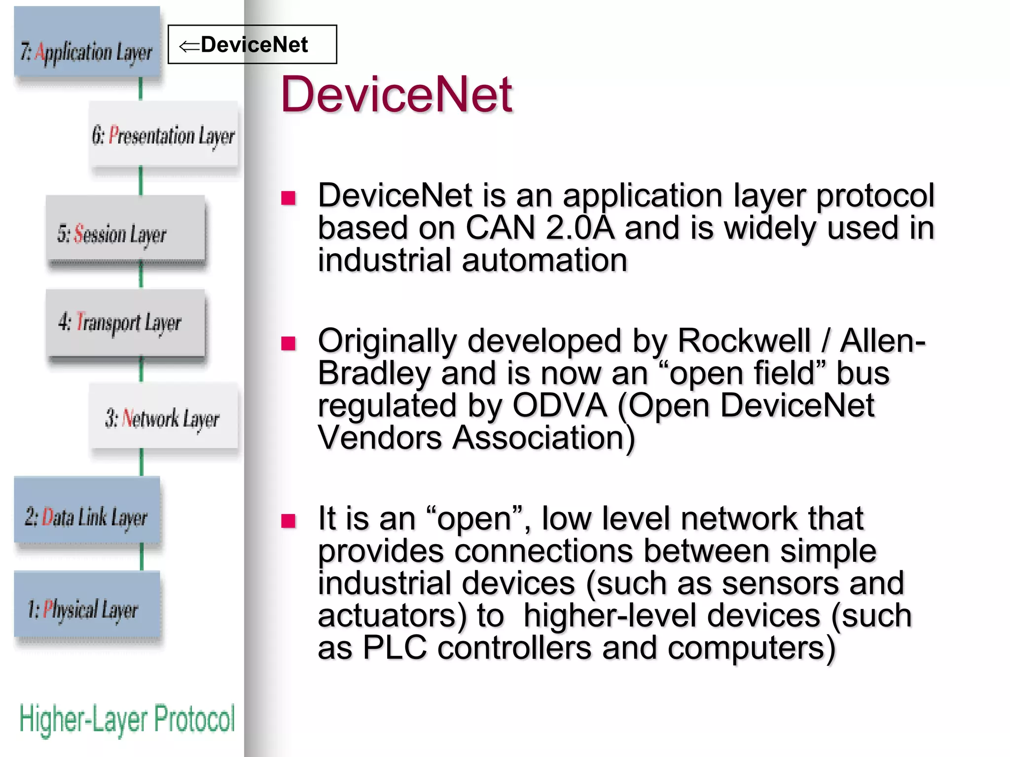
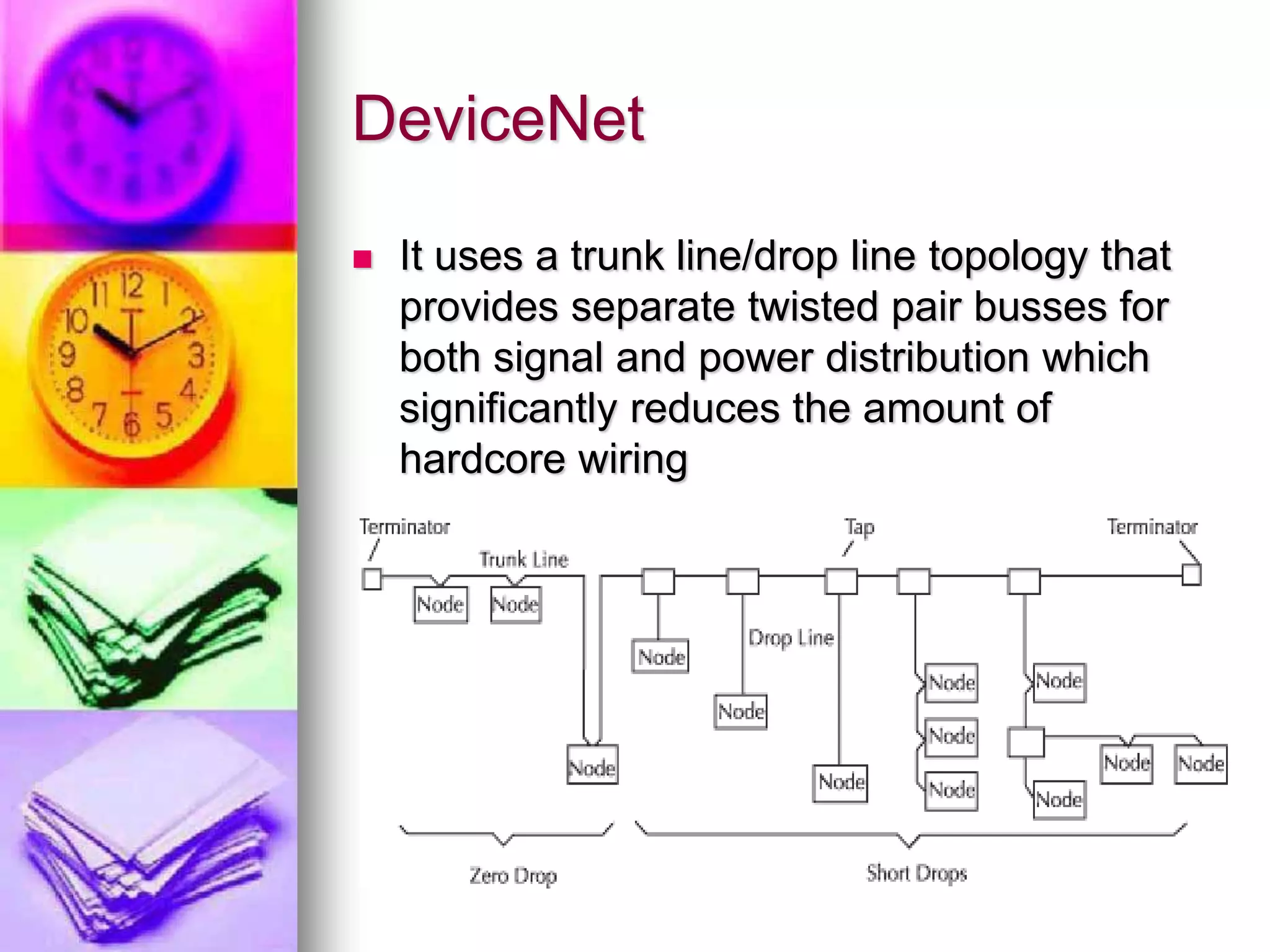
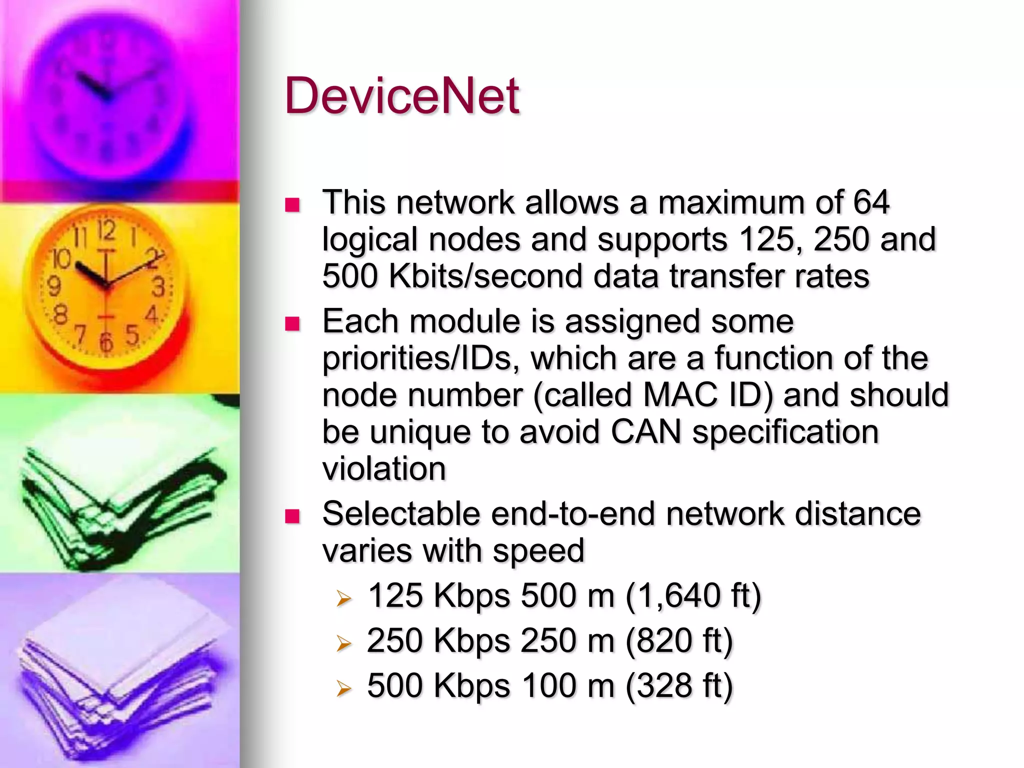
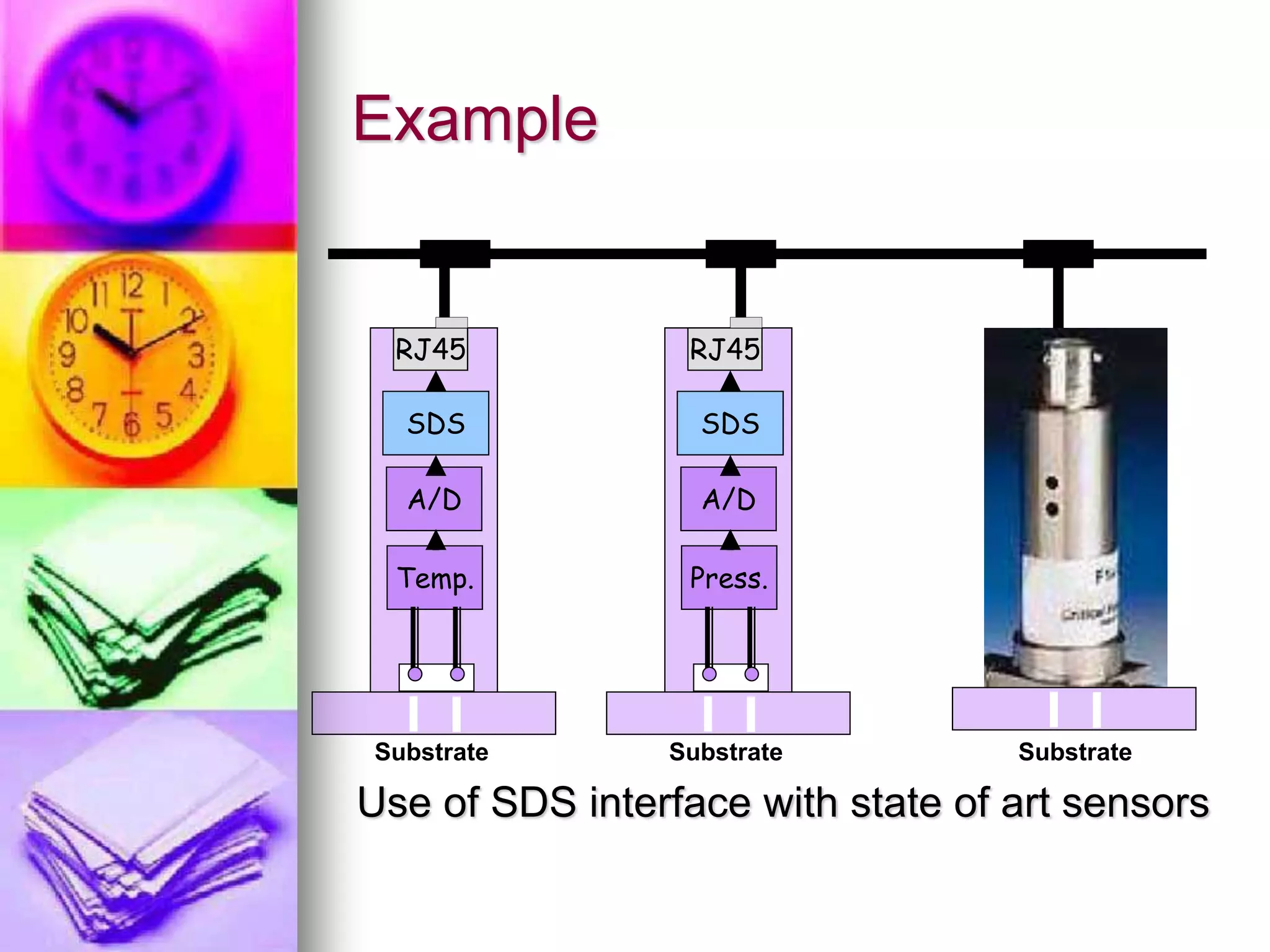
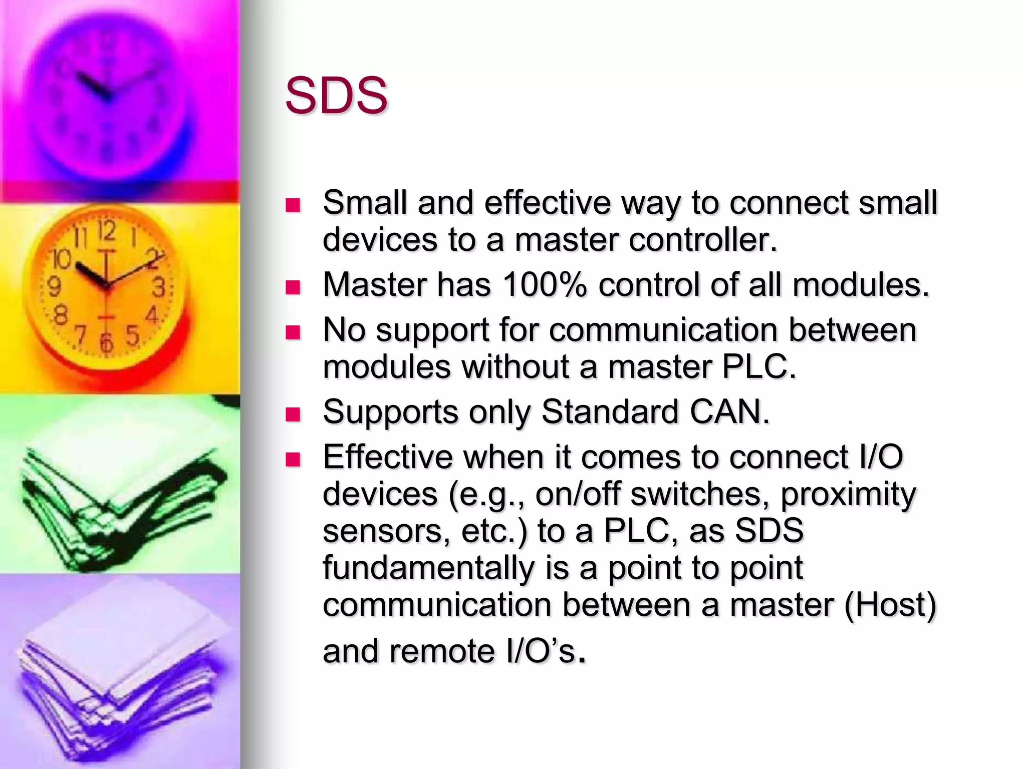
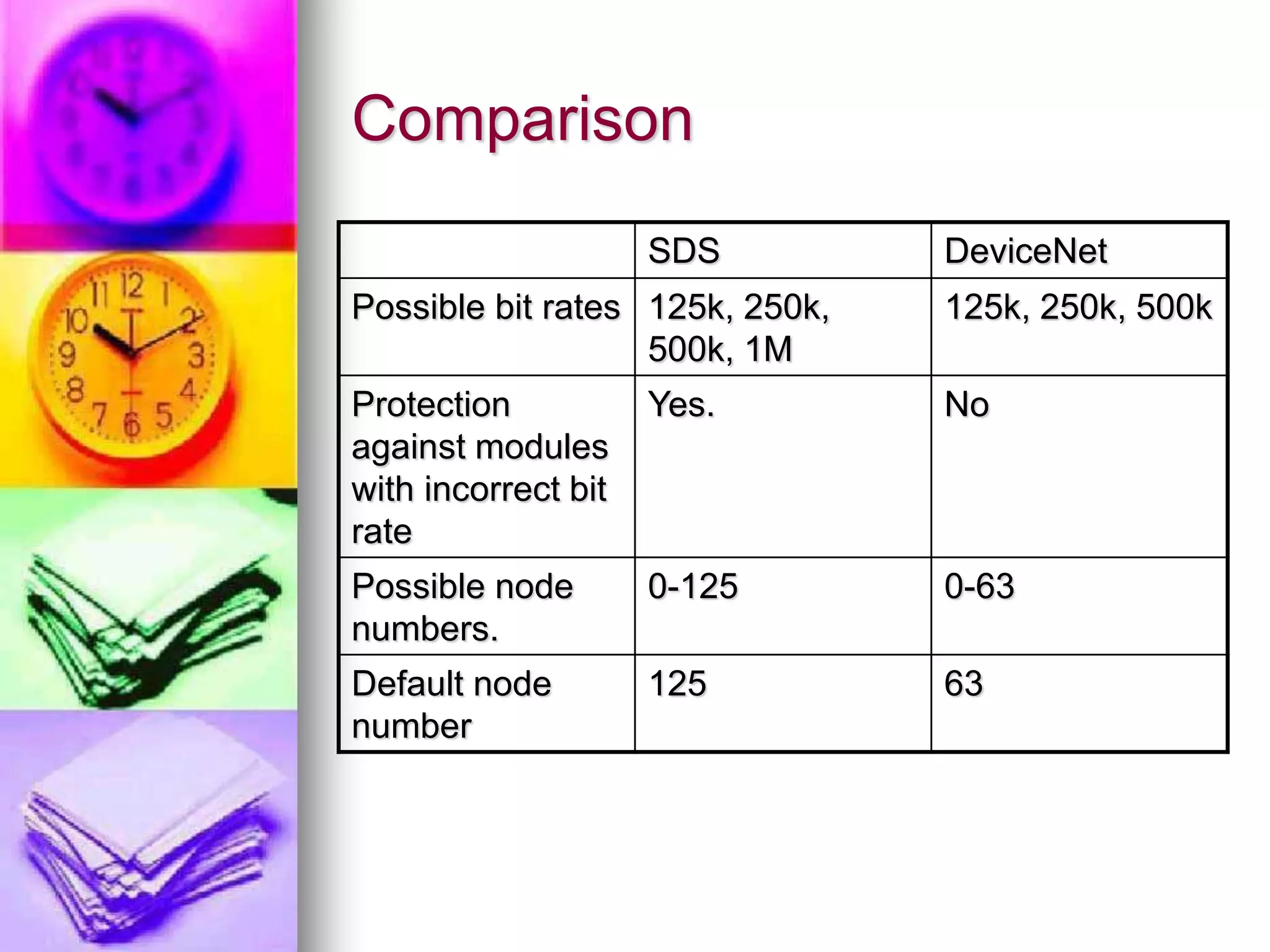


The document provides information about DeviceNet and Smart Distributed Systems (SDS), two industrial communication protocols based on CAN bus. DeviceNet was developed by Rockwell and uses a trunk/drop topology to connect devices like sensors to controllers. It supports up to 64 nodes at speeds up to 500kbps. SDS was developed by Honeywell for connecting intelligent sensors and actuators and supports up to 125 nodes at speeds up to 1Mbps. The document compares aspects of the two protocols such as maximum bit rates, number of supported nodes, and default node numbers.


