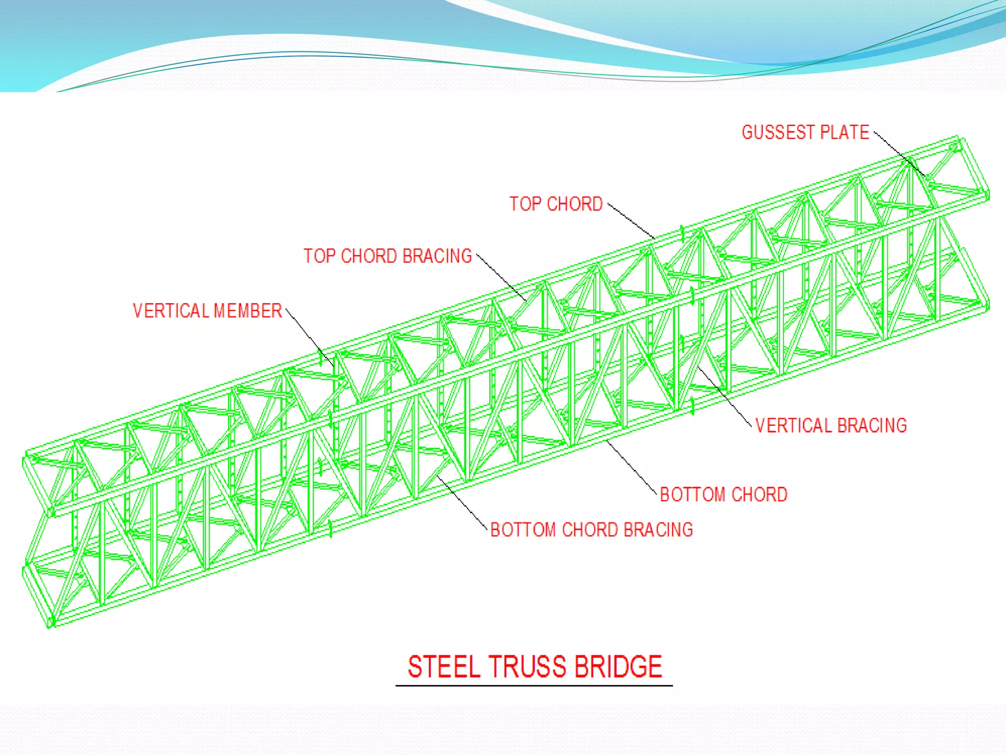
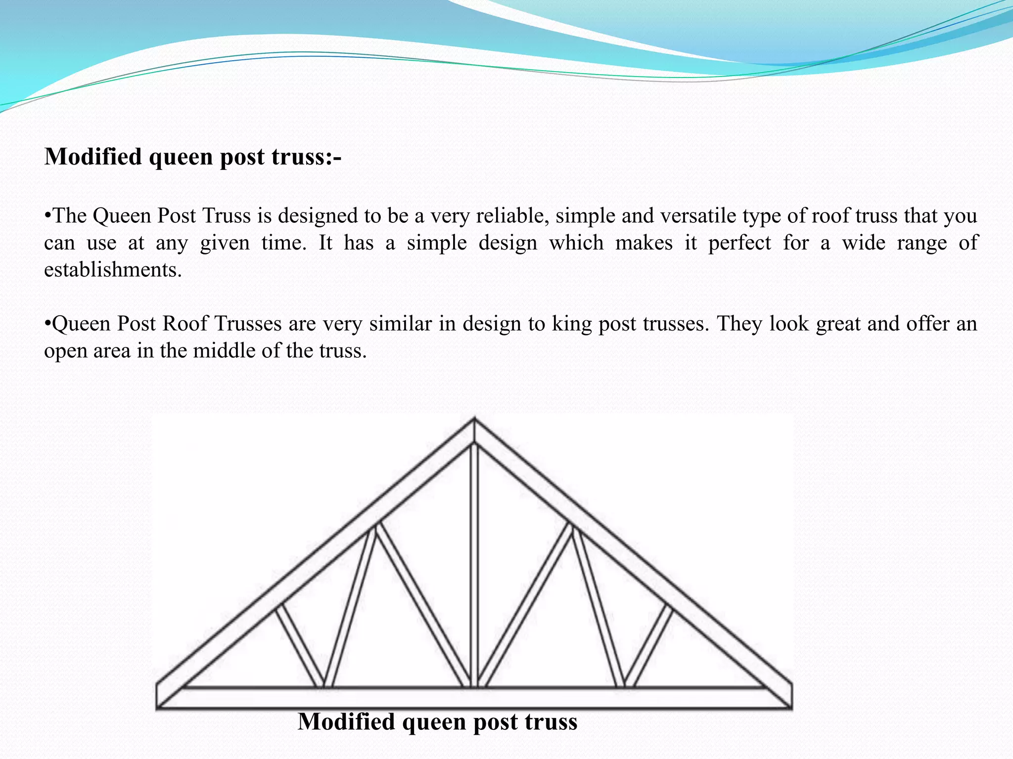
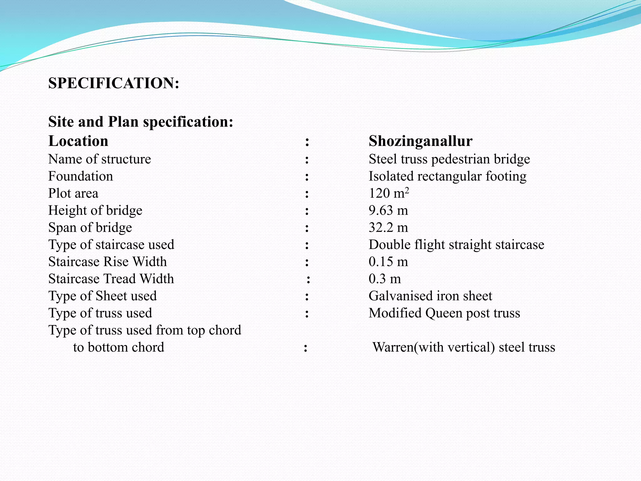
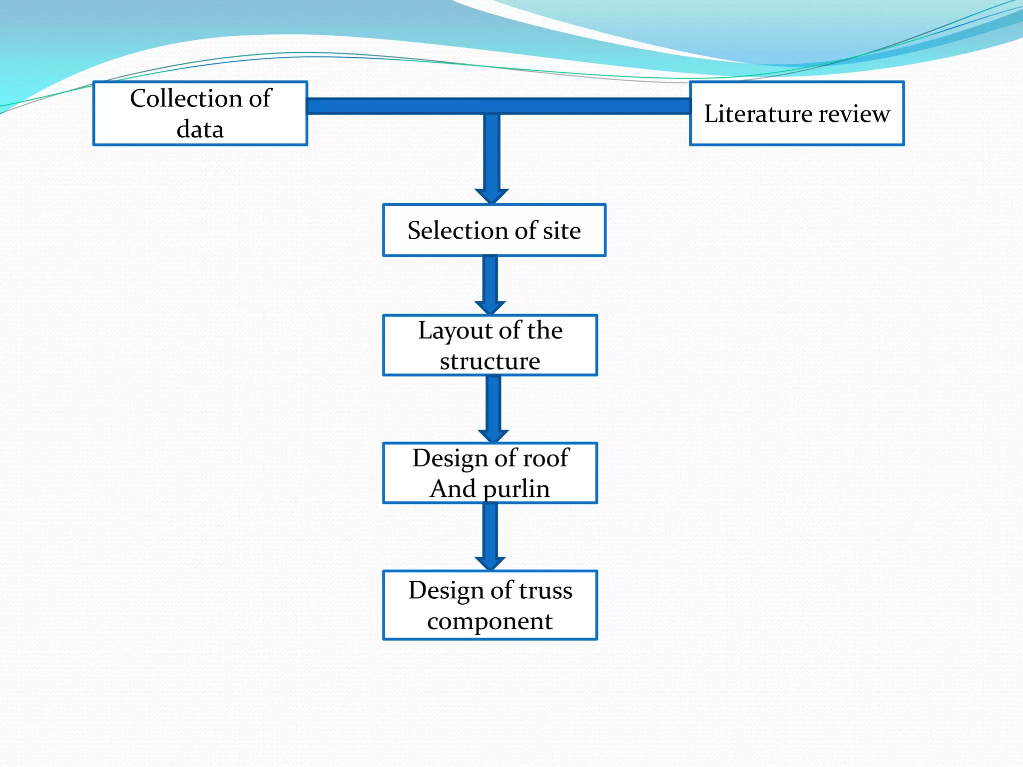
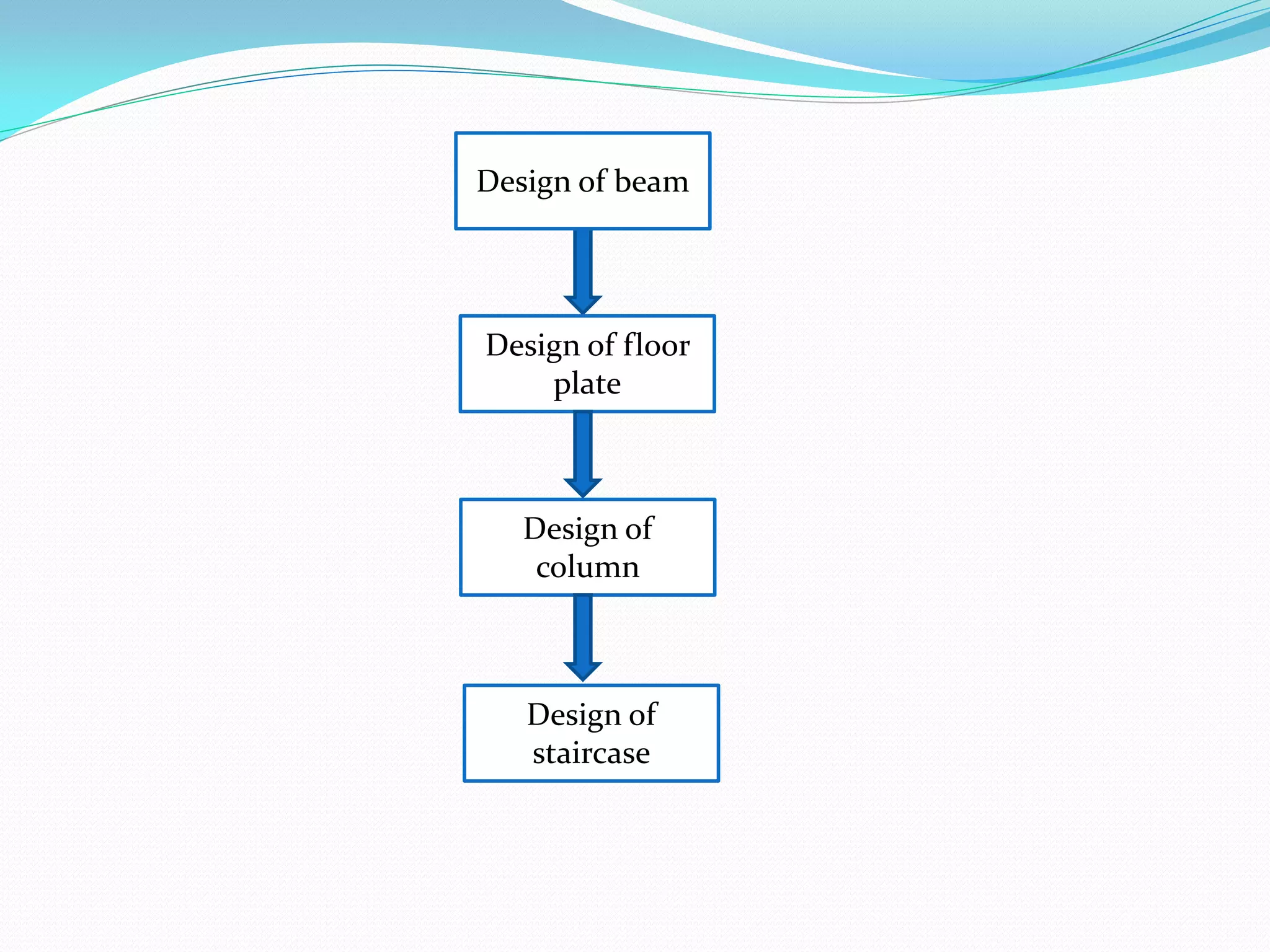
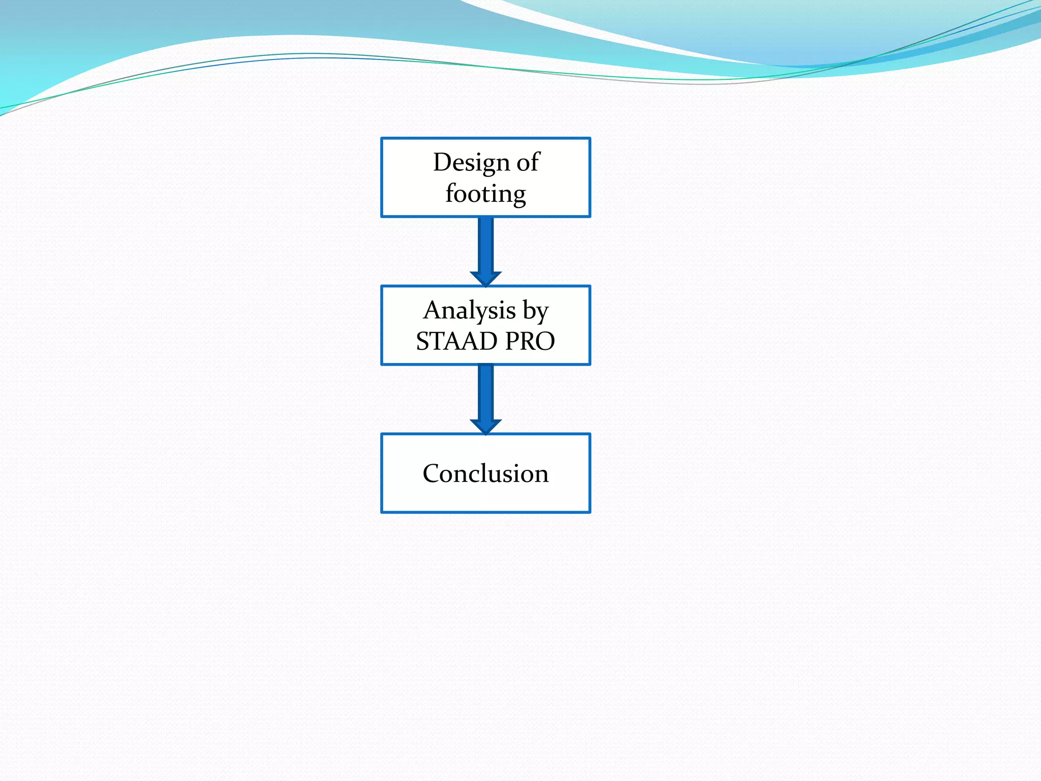
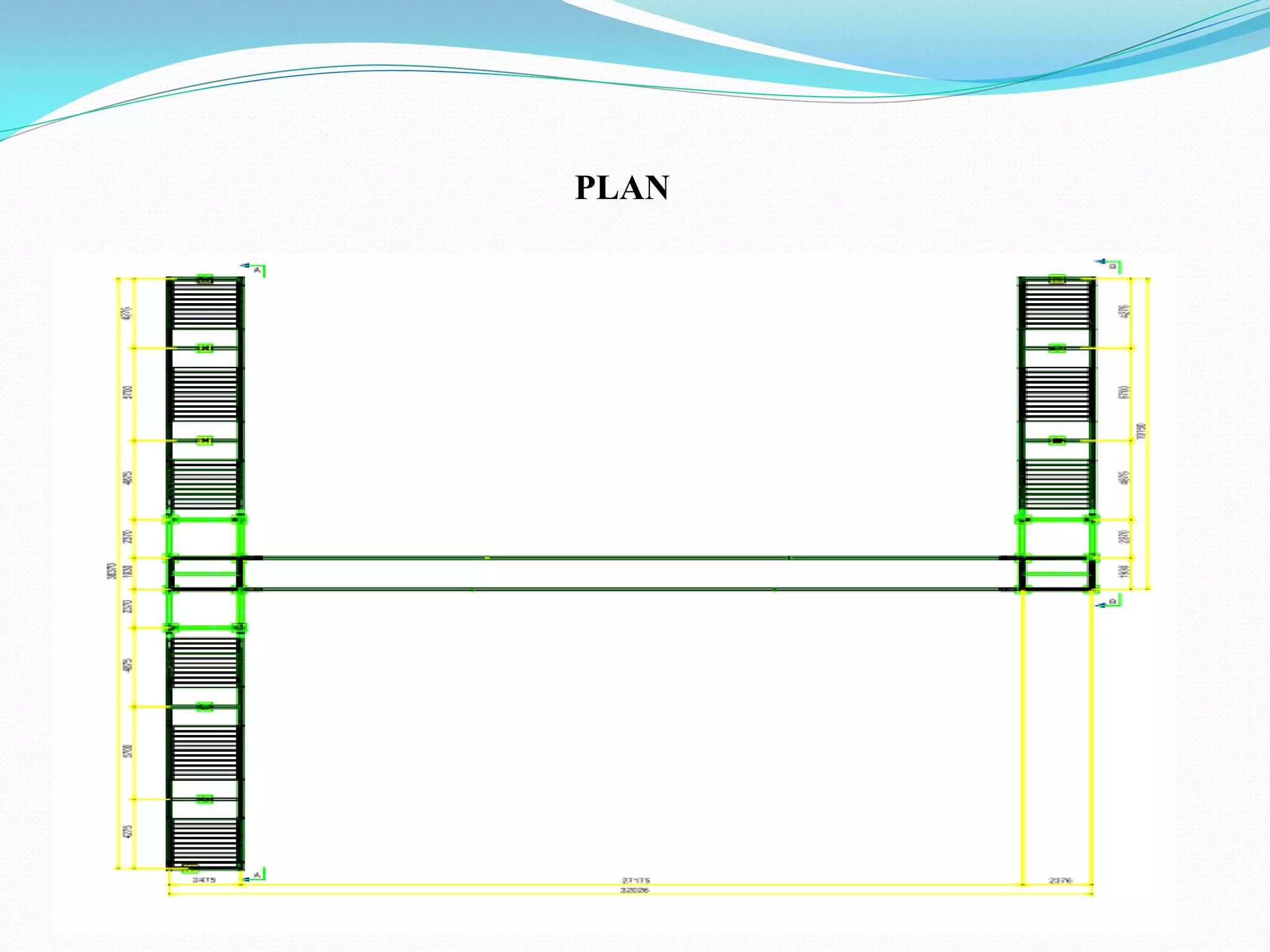
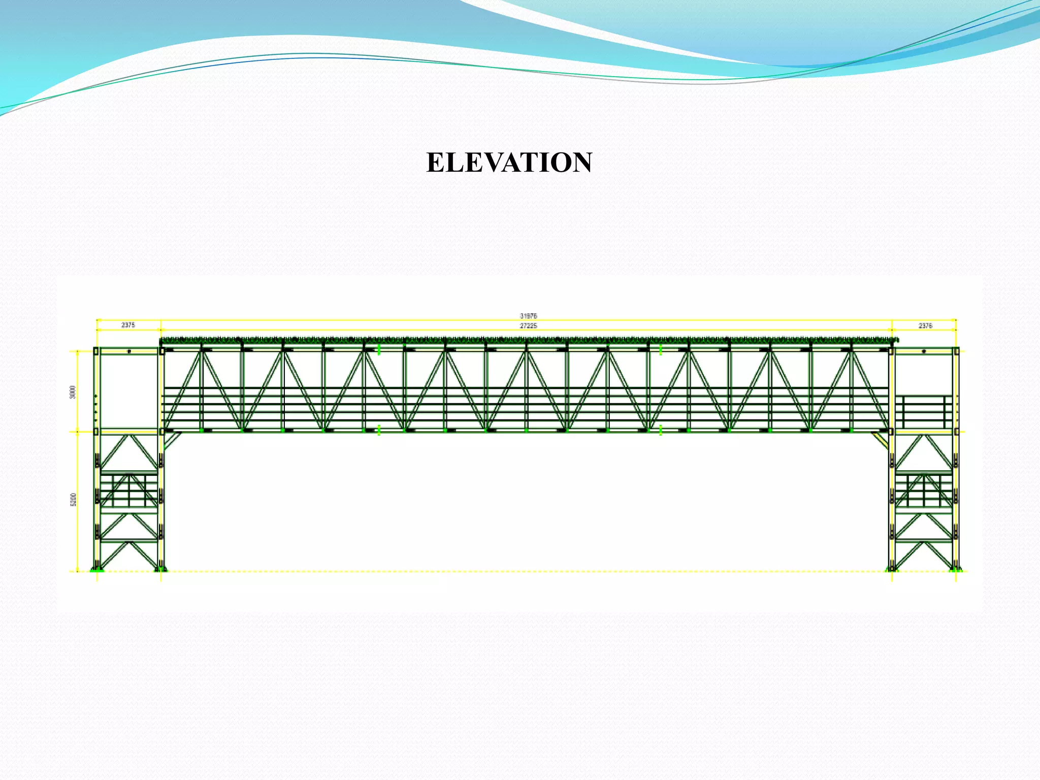
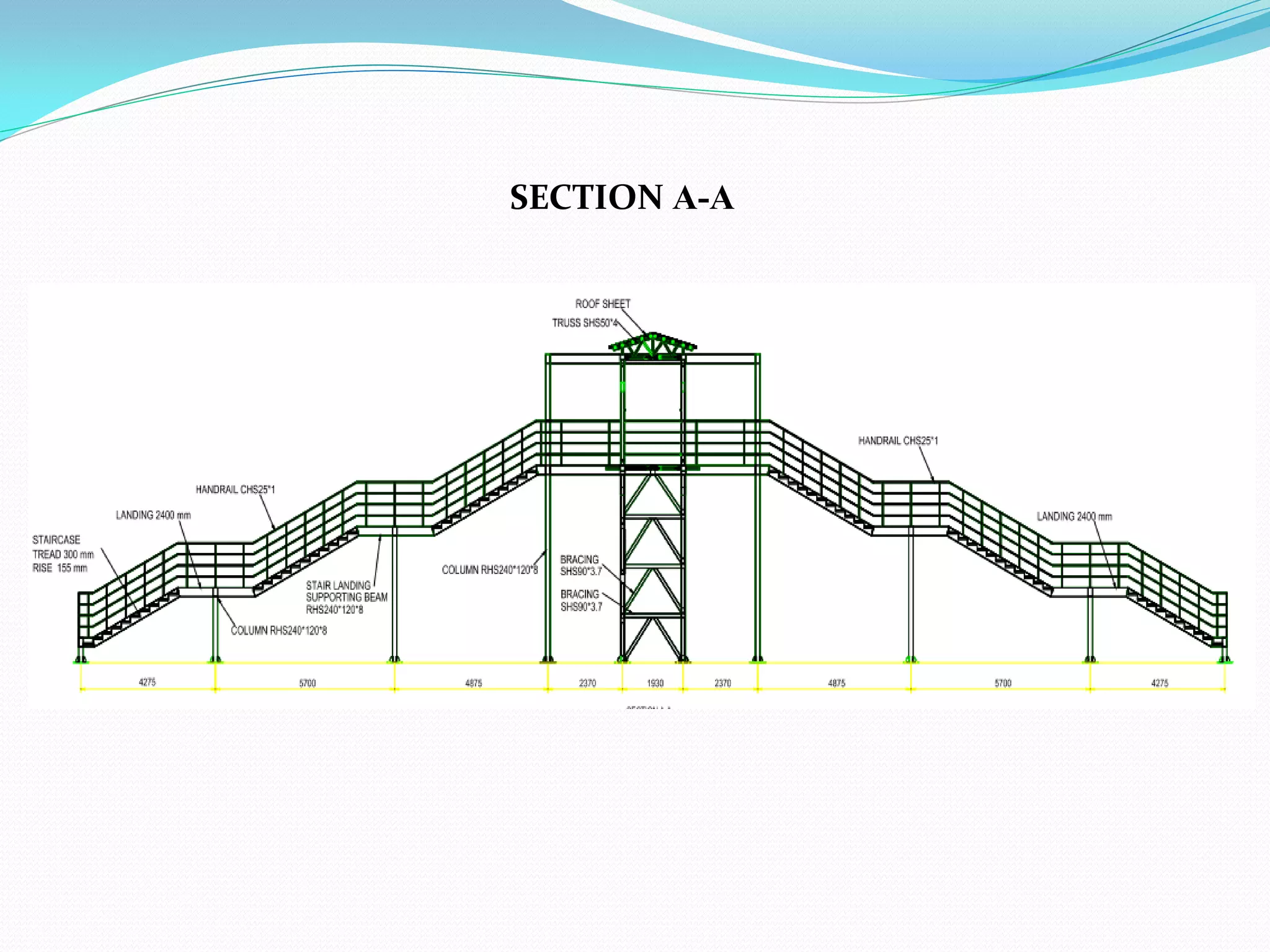
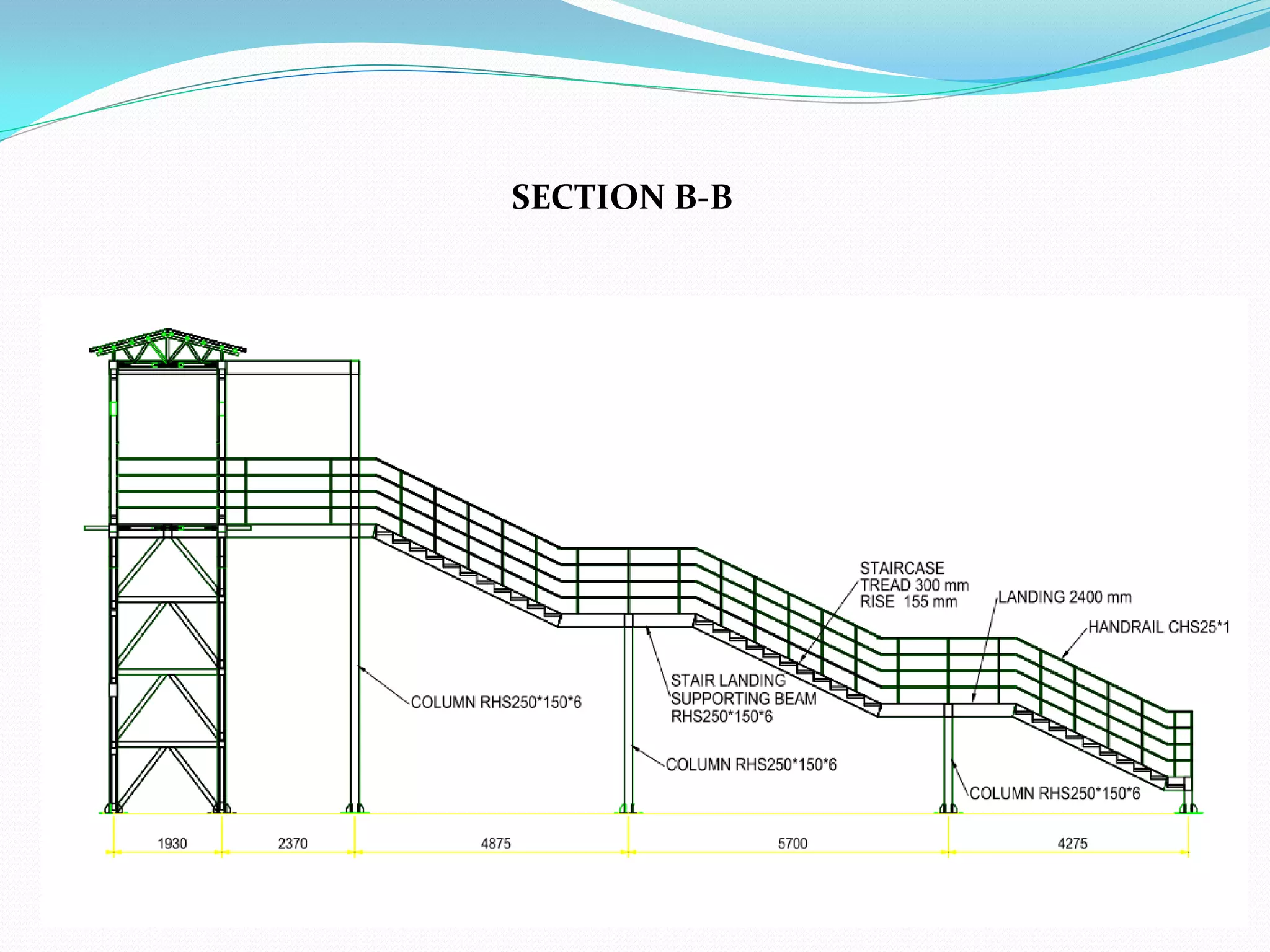
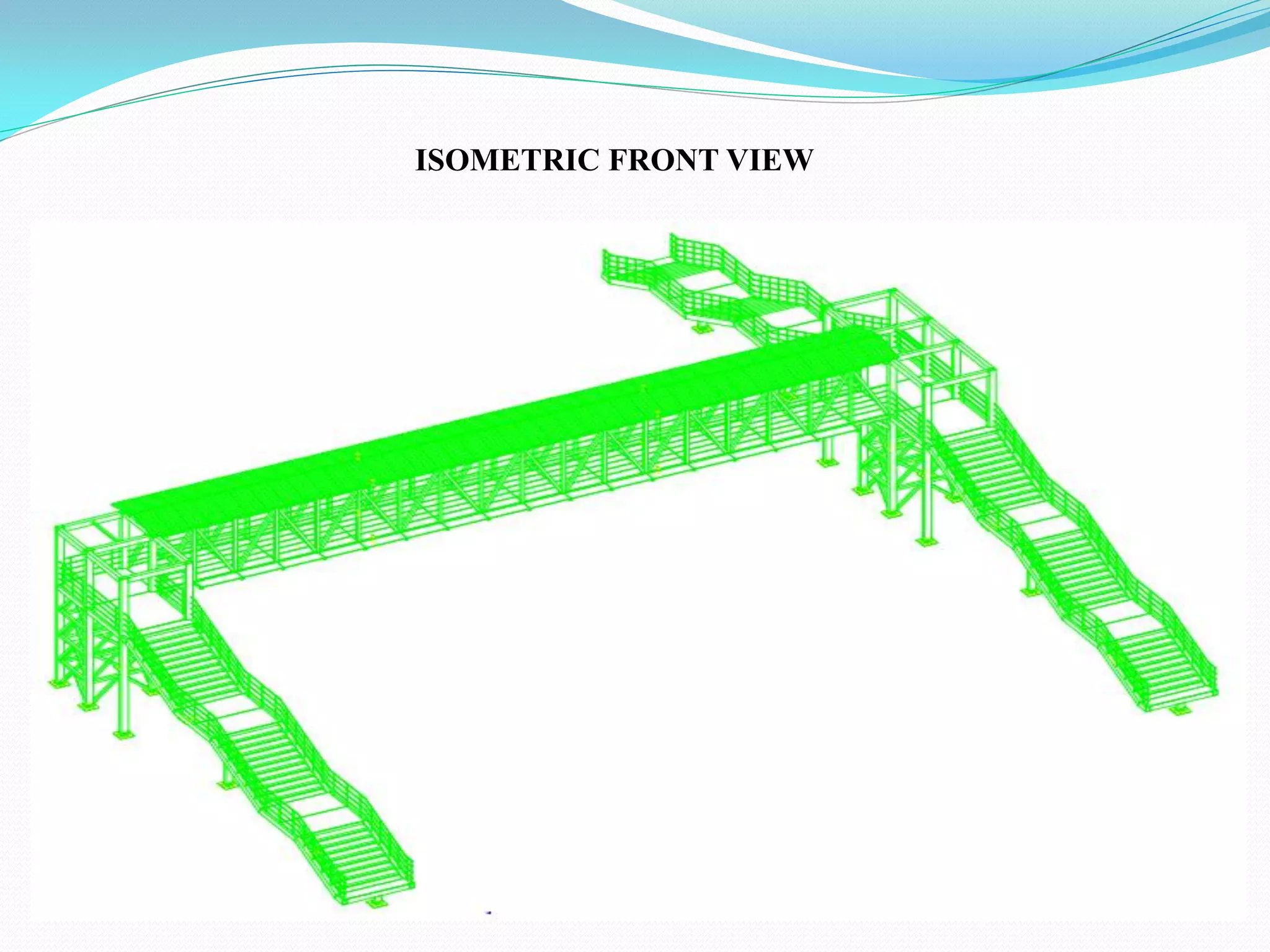
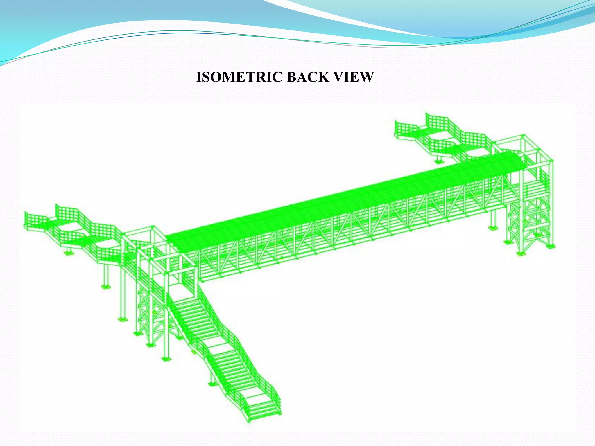
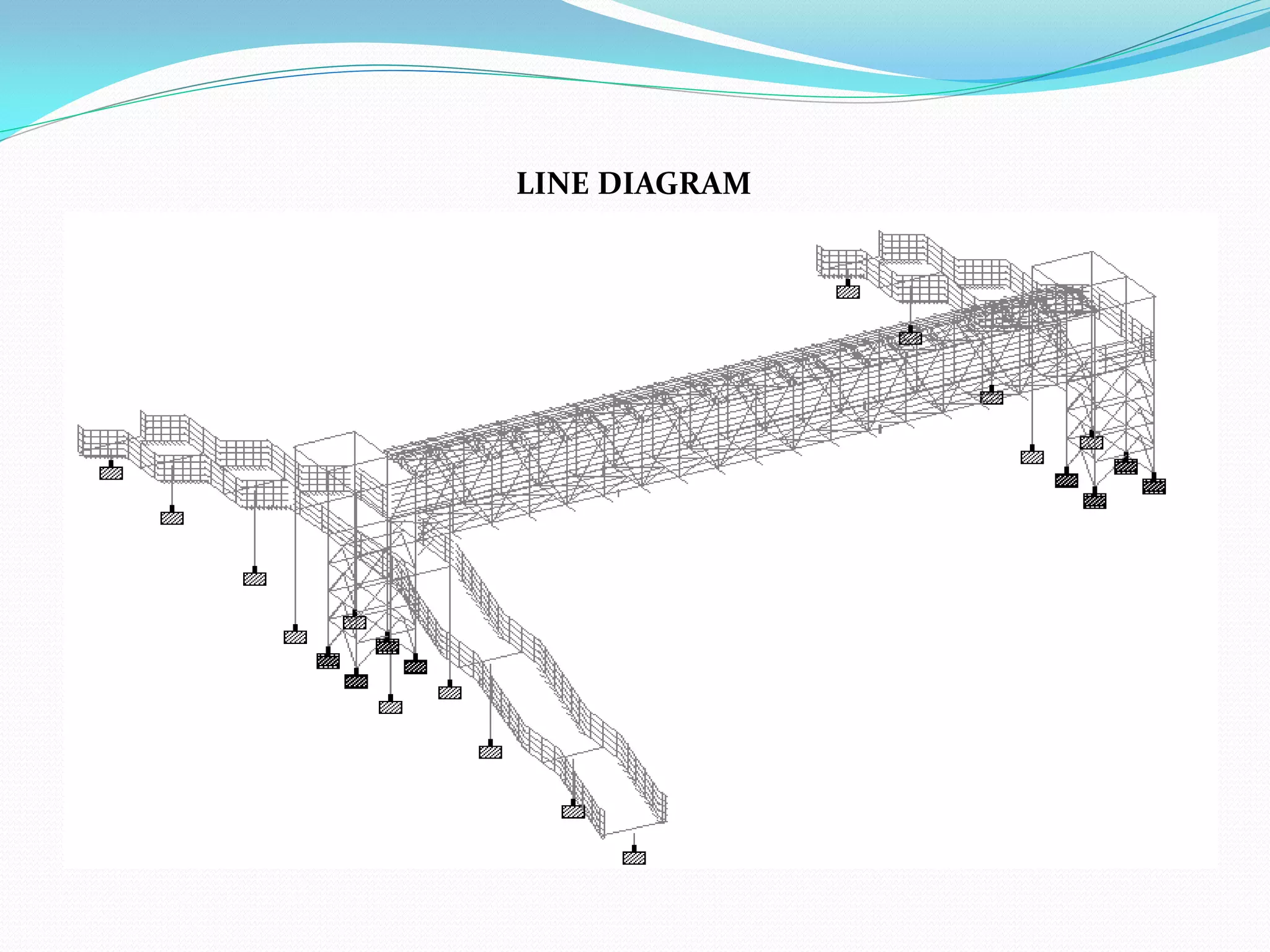
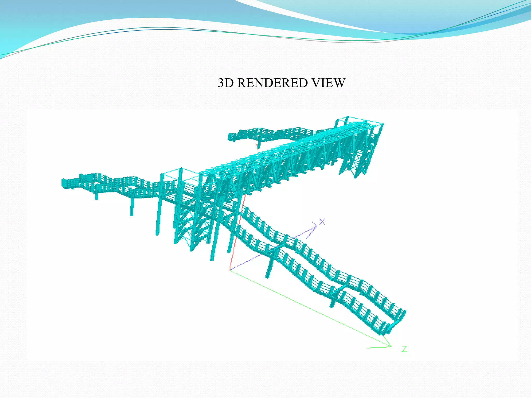
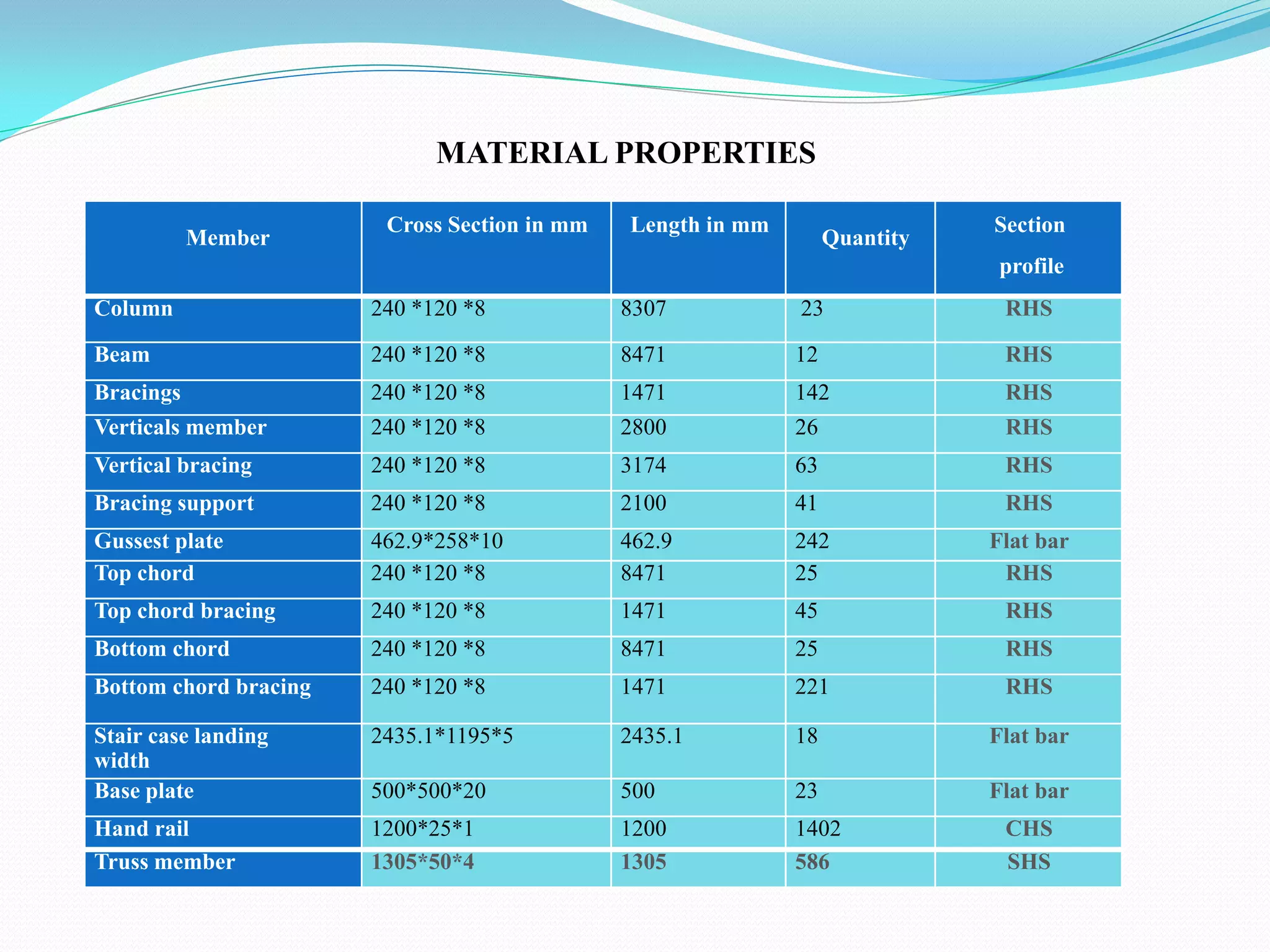
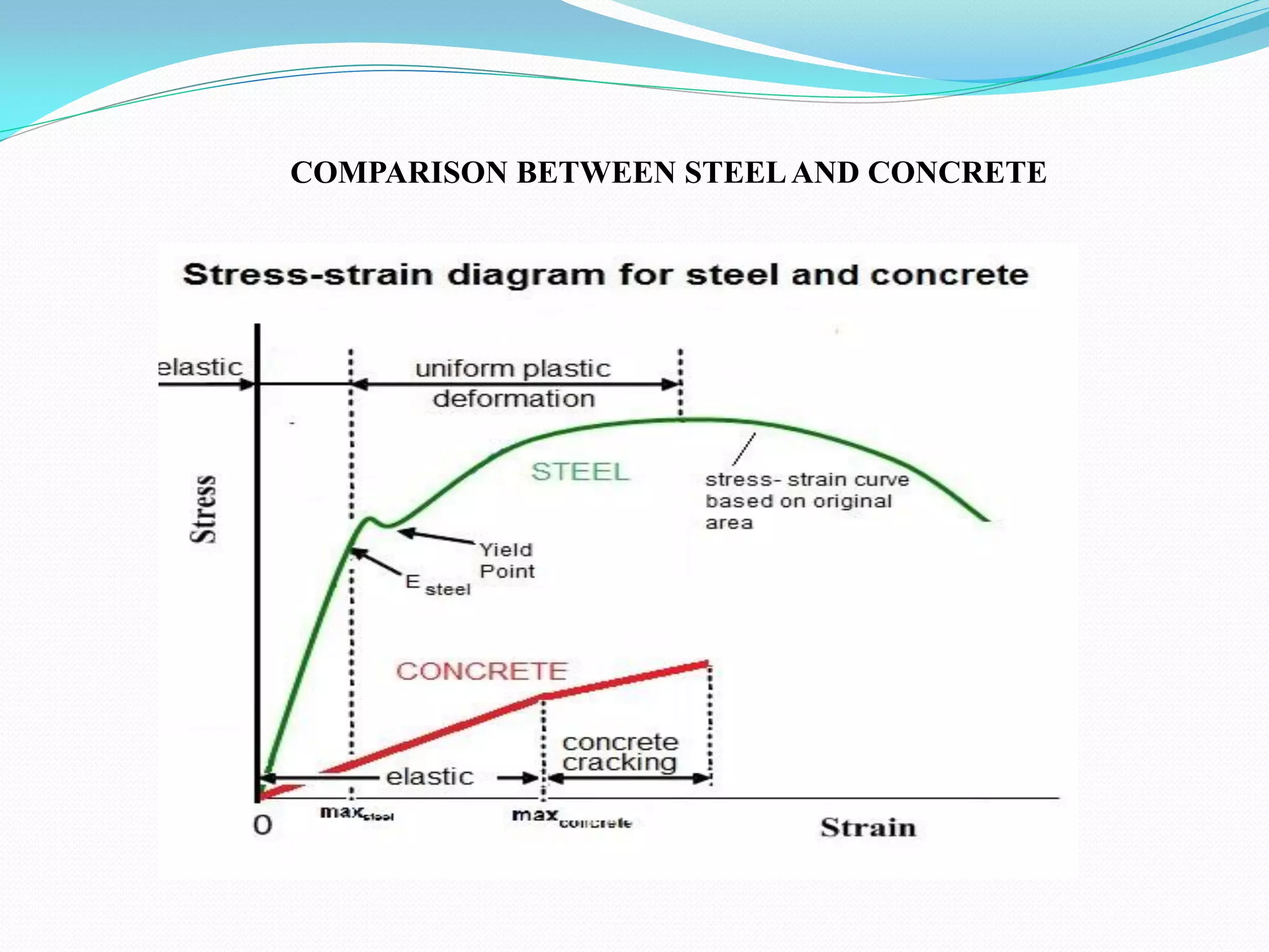
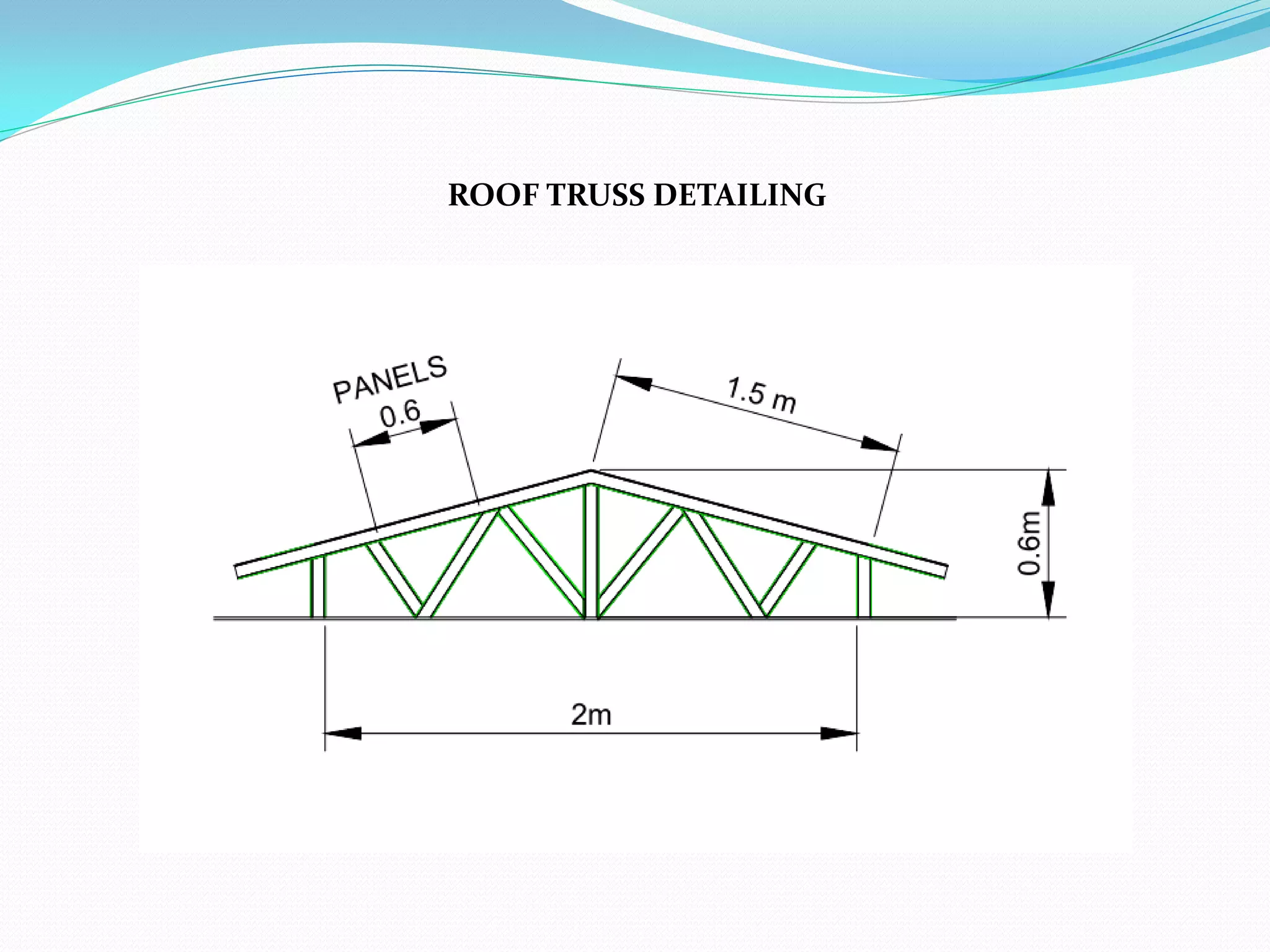
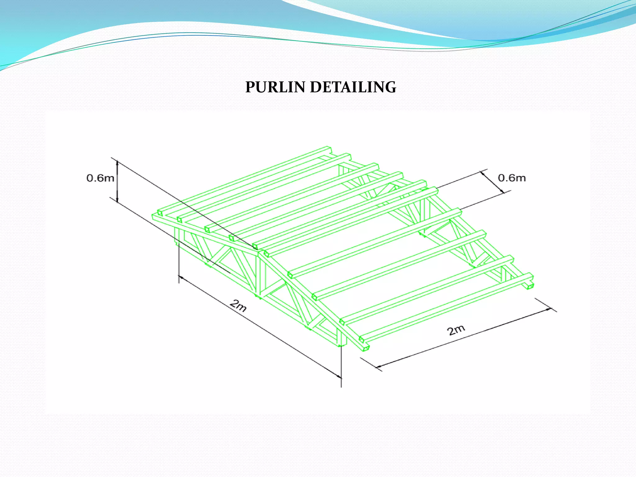
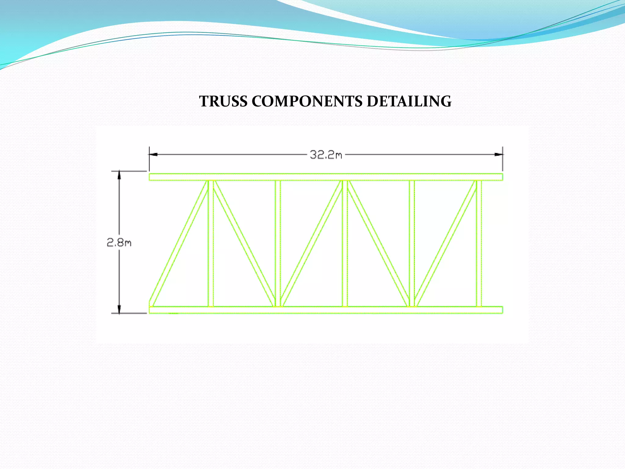
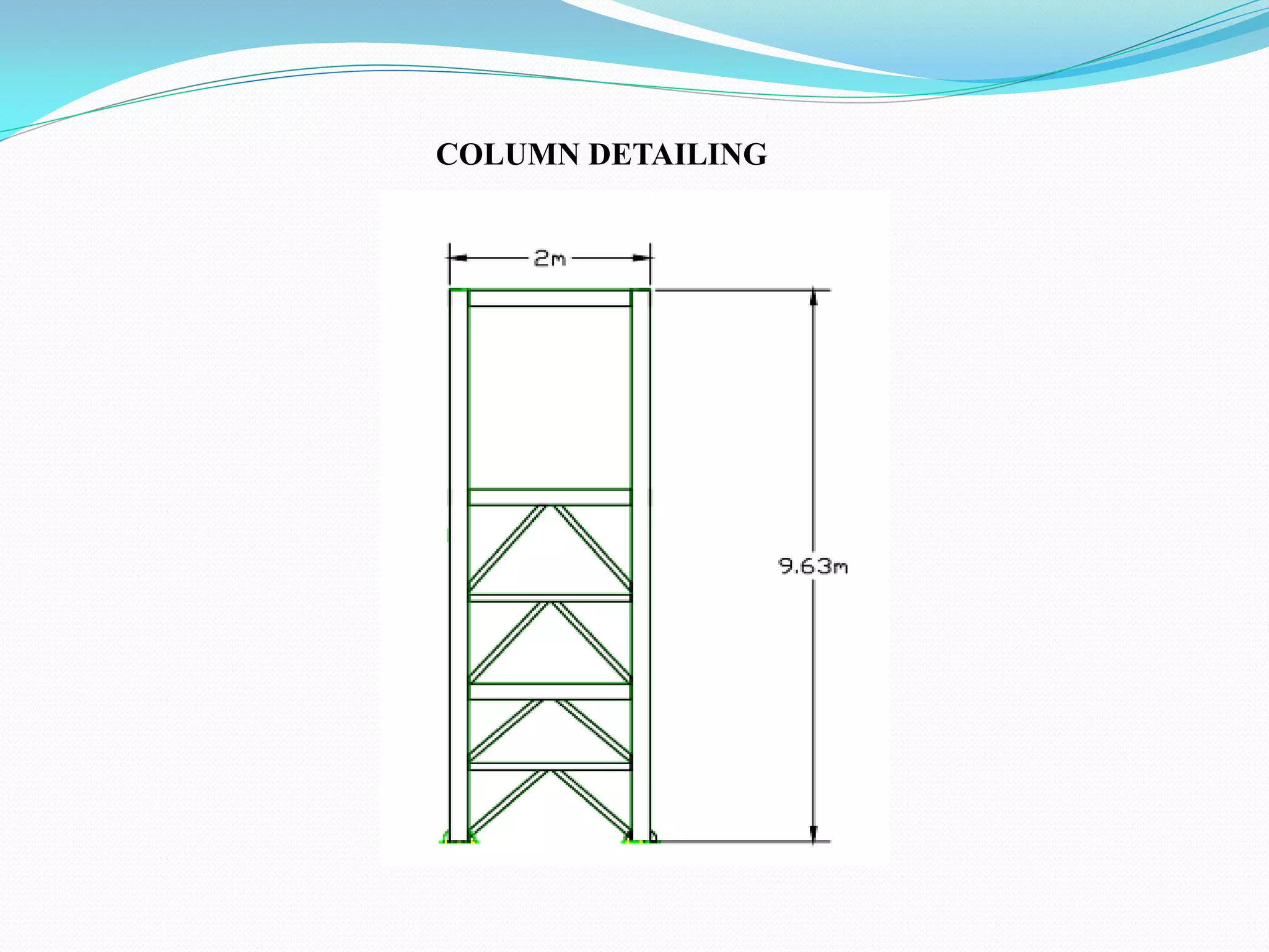
ABSTRACT
A lattice steel truss foot over bridge with an Isolated foundation is analyzed and designed. The
superstructure is a steel structure at a height of 9.63m from the ground level. The analysis and
design of the super structure is done using STAAD PRO software and modeling is done using
TEKLA structure software and drawing is done by using AUTO CAD.
CONTENTS
1. INTRODUCTION
2. LITERATURE REVIEW
3. METHODOLOGY
4. AUTO CAD DRAWINGS
5. TEKLA STRUCTURE DRAWINGS
6. STAAD PRO DREAWINGS
7. MATERIAL PROPERTIES
8. DESIGN
9. FABRICATION OF STEEL
10. CONCLUSION
INTRODUCTION
 A foot over bridge is a bridge designed for pedestrians. Foot over bridges can be used
decoratively to visually link two distinct areas or to signal a transaction. Bridges providing for
both pedestrians and cyclists are often referred to as green bridges and form an important part of
sustainable transport movement towards more sustainability’s. Footbridges are often situated to
allow pedestrians to cross water. They are also located across roads to let pedestrians cross safely
without slowing down the traffic.
 Footbridges are small, but important, because they are usually presented in townscape. The
appearance of footbridges, and indeed of any other bridges, in a town, is a major concern for
designers.
 Footbridges can also be built in the same ways as road and rail bridges. Most footbridges are
equipped with guard rails to reduce the risk of pedestrians falling.
Need:-
The increasing pedestrian traffic on road crossings, junctions and inaccessible road terminals in the
cities of our country. Unlike subways, steel pedestrian bridges are less economical, easy and fast to
construct. The need of the study is to determine the combined strength and efficiency of the steel
truss foot over bridge.
Objective:-
• To Design economical, safe and simple to assemble steel truss bridge for pedestrian
crossing purpose.
• Design locally available steel truss bridge.
• To develop analysis and design procedure for steel truss bridge.
• Simulating steel truss bridge Design using STADD PRO.
• Model 3D of steel truss using software like TEKLA structure.
• Drawings like Plan, Elevation, Section using AUTO CAD.
Scope:-
• The scope of the study has been limited to design and assemble of simple steel truss foot over
bridge for Shozinganallur main junction. Main components of the steel truss were analysed using
STADD PRO software.
• This design did not consider disabled pedestrians.
Advantage:-
Using Steel truss bridges have many advantages, some of them are:
1. Less cost (economical).
2. Simple to assemble.
3. Flexibility in design.
4. Resistance to dynamic loads.
5. Easy maintenance.
6. Safe.
Steel truss:-
• Steel truss is widely used around the world for the construction of bridges of different size. It is a
effective material that provides efficient and sustainable solutions. Steel has long been recognized
as the economic option for a range of bridges.
• It dominates the markets for long span bridges, railway bridges, footbridges, and medium span
highway bridges. It is now increasingly the choice for shorter span highway structures as well.
Modified queen post truss:-
•The Queen Post Truss is designed to be a very reliable, simple and versatile type of roof truss that you
can use at any given time. It has a simple design which makes it perfect for a wide range of
establishments.
•Queen Post Roof Trusses are very similar in design to king post trusses. They look great and offer an
open area in the middle of the truss.
Modified queen post truss
GENERAL:
The main purpose of literature review is to give an idea about the research work conducted in the world.
This form the basis on which one carry out the work and techniques that can be used for conducting the
experiments.
Truss Bridge: Truss structures are composed of members that are connected to form a rigid frame of
steel. This broad application can be used in many areas, such as pedestrian crossing bridge, rail road
and other transportation bridges.
Vinay Agarwala described the design of structures whether steel are governed by code provisions. In
structural engineering the primary goal of optimization lies in either minimizing the weight of the
structure or reducing its cost, keeping in view the overall safety and serviceability aspects. Engineering
design is influenced by several parameters and associated constraints hence while designing a structure
numerous solutions are obtained.
LITERATURE REVIEW
Midhun B Sankar described the popularity of steel bridges is increasing in the modern era because
of its unmatchable advantages. Engineers are using various national codes to achieve an optimum
design. Some of the Asian countries are using their own codes and also American and other country
code provisions to achieve better economy and better standards. In this regard the comparison of design
codes is relevant.
William Holabird & Ossian Cole Simonds described the steel pedestrian bridge which is the
new destination for residents and visitors of Davenport, Iowa, to experience the Mississippi riverfront.
The structure, a distinctive cable-stayed style bridge with 99 foot columns, spans 575 feet over a
parking garage, highway, and heavily used railway tracks as part of the city’s “River Renaissance”
redevelopment project. At night, LED lights create a rainbow of colors and penetrate glass panels set in
the floor of the walkway, illuminating the streetscape.
Ronald J. Watson described the South Carolina Department of Transportation (SCDOT) upgraded
their seismic design requirements by adopting revisions to the American Association of State Highway
and Transportation Officials (AASHTO) Standard Specification for Highway Bridges, Seismic Design
Provisions of Division I-A. Not long after this the SCDOT secured the services of Earth Tech, Inc.
Consulting Engineers to design two new replacement overpasses over I-26 in Charleston, South
Carolina. These bridges replace the existing structures carrying US Route 52 and Ashley Phosphate
Road over I-26.
METHODOLOGY
The methodology of this design project commences with the drafting of the plan for the steel truss foot
over bridge. Instead of normal roofing design, the structure has been designed in GI sheets. Steel
roofing has been provided with larger space equal distance. The roofing is nothing but galvanised iron
steel provided with larger space. The design loads are applied and analysis of the superstructure is done
using STAAD PRO software.
SITE SELECTION :
•The safe bearing capacity of soil in the site should be checked accordingly, for the bridge to be
constructed in the locality.
•The pedestrian bridge should be constructed in such a way that it can be extended to longer length in
future either straight or perpendicular to 32.2m span bridge.
•The site should be chosen in such a way that the pedestrian bridges to be constructed in the site would
facilitate the pedestrians to have easy access to the routes so that they can move to their destinations
places with comfort.
LOAD CALCULATION:
S.NO LOAD MAGNITUDE
1 Dead load Self-weight of structure
2 Live load 5 KN/m2
3 Wind load 1.5 KN/m2
SPECIFICATION:
Site and Plan specification:
Location : Shozinganallur
Name of structure : Steel truss pedestrian bridge
Foundation : Isolated rectangular footing
Plot area : 120 m2
Height of bridge : 9.63 m
Span of bridge : 32.2 m
Type of staircase used : Double flight straight staircase
Staircase Rise Width : 0.15 m
Staircase Tread Width : 0.3 m
Type of Sheet used : Galvanised iron sheet
Type of truss used : Modified Queen post truss
Type of truss used from top chord
to bottom chord : Warren(with vertical) steel truss
Literature review
Selection of site
Layout of the
structure
Design of roof
And purlin
Design of truss
component
Collection of
data
Design of floor
plate
Design of
column
Design of
staircase
Design of beam
Analysis by
STAAD PRO
Conclusion
Design of
footing
AUTO CAD DRAWINGS
PLAN
ELEVATION
SECTION A-A
SECTION B-B
TEKLA STRUCTURE DRAWINGS
ISOMETRIC FRONT VIEW
ISOMETRIC BACK VIEW
STADD PRO DRAWINGS
LINE DIAGRAM
3D RENDERED VIEW
Member
Cross Section in mm Length in mm
Quantity
Section
profile
Column 240 *120 *8 8307 23 RHS
Beam 240 *120 *8 8471 12 RHS
Bracings 240 *120 *8 1471 142 RHS
Verticals member 240 *120 *8 2800 26 RHS
Vertical bracing 240 *120 *8 3174 63 RHS
Bracing support 240 *120 *8 2100 41 RHS
Gussest plate 462.9*258*10 462.9 242 Flat bar
Top chord 240 *120 *8 8471 25 RHS
Top chord bracing 240 *120 *8 1471 45 RHS
Bottom chord 240 *120 *8 8471 25 RHS
Bottom chord bracing 240 *120 *8 1471 221 RHS
Stair case landing
width
2435.1*1195*5 2435.1 18 Flat bar
Base plate 500*500*20 500 23 Flat bar
Hand rail 1200*25*1 1200 1402 CHS
Truss member 1305*50*4 1305 586 SHS
MATERIAL PROPERTIES
COMPARISON BETWEEN STEELAND CONCRETE
ROOF TRUSS DETAILING
PURLIN DETAILING
TRUSS COMPONENTS DETAILING
FLOOR PLATE DETAILING
COLUMN DETAILING
FOOTING REINFORCEMENT
FABRICATION OF STEEL
Cutting of steel:
IS-2001 (Fabrication Specification) as under:
Provided the edge as given by the torch is reasonable clean and straight, plates may be cut to shape
and beams and other sections cut to length with a gas cutting torch.
Layout:
The layout of structure on template floor is the most important operation in fabrication. Steel flooring
is desirable, as it would also minimize variation in dimensions due to temperature changes. The
marking tools and instruments like square, divider, punches, steel scriber should be of good quality.
Calibrated tape for measurement of lay out must be used.
Drilling of holes:
Quality of fabrication shall be improved if jigs are used during fabrication. Drilling of the component
may be done through jigs. All burrs left by the drill and sharp edges of the holes shall be removed.
Welding Process and Positions:
Welding shall be carried out in accordance with the approved welding procedure, specifications by
approved welders, processes and positions. Performance for welding procedure specification and
welding procedure qualification records are enclosed.
Final Cutting and Finishing of component:
Final finishing of length, profile and notches.
Inspection Stages:
(a) Before fabrication
(b) During fabrication
(c) After fabrication
(a) Before fabrication
• Quality Assurance Plan shall be prepared and got approved.
• Raw material such as channels and plates etc.
• Welders approval as per Welding Procedure Specification.
(b)During Fabrication :
• Lay out, jigs and fixtures and profile to be check
• Welding parameters are to be set & checked during welding.
(c) After Fabrication :
• Surface defects shall be checked visually.
• Quality of rivets to be checked visually and with the help of riveting hammer.
CONCLUSION
The section with the overview of the entire project report. The lattice steel truss is
analysed by STAAD PRO and the result is obtained. The load considered for the
structure are the dead load, live load ,wind load(50m/s). The design of HSFG
bolted and weld connections are described. The design of lattice steel truss, and
roofing are designed based on the provisions according to code book
IS800:2007,steel table. Based on the analysis and design made so far, the study
has proved that, construction of steel bridge with locally available steel profiles is
an option worth.
THANK
YOU

Design of Foot Over Bridge

  • 2.
    ABSTRACT A lattice steeltruss foot over bridge with an Isolated foundation is analyzed and designed. The superstructure is a steel structure at a height of 9.63m from the ground level. The analysis and design of the super structure is done using STAAD PRO software and modeling is done using TEKLA structure software and drawing is done by using AUTO CAD.
  • 3.
    CONTENTS 1. INTRODUCTION 2. LITERATUREREVIEW 3. METHODOLOGY 4. AUTO CAD DRAWINGS 5. TEKLA STRUCTURE DRAWINGS 6. STAAD PRO DREAWINGS 7. MATERIAL PROPERTIES 8. DESIGN 9. FABRICATION OF STEEL 10. CONCLUSION
  • 4.
    INTRODUCTION  A footover bridge is a bridge designed for pedestrians. Foot over bridges can be used decoratively to visually link two distinct areas or to signal a transaction. Bridges providing for both pedestrians and cyclists are often referred to as green bridges and form an important part of sustainable transport movement towards more sustainability’s. Footbridges are often situated to allow pedestrians to cross water. They are also located across roads to let pedestrians cross safely without slowing down the traffic.  Footbridges are small, but important, because they are usually presented in townscape. The appearance of footbridges, and indeed of any other bridges, in a town, is a major concern for designers.  Footbridges can also be built in the same ways as road and rail bridges. Most footbridges are equipped with guard rails to reduce the risk of pedestrians falling.
  • 5.
    Need:- The increasing pedestriantraffic on road crossings, junctions and inaccessible road terminals in the cities of our country. Unlike subways, steel pedestrian bridges are less economical, easy and fast to construct. The need of the study is to determine the combined strength and efficiency of the steel truss foot over bridge. Objective:- • To Design economical, safe and simple to assemble steel truss bridge for pedestrian crossing purpose. • Design locally available steel truss bridge. • To develop analysis and design procedure for steel truss bridge. • Simulating steel truss bridge Design using STADD PRO. • Model 3D of steel truss using software like TEKLA structure. • Drawings like Plan, Elevation, Section using AUTO CAD. Scope:- • The scope of the study has been limited to design and assemble of simple steel truss foot over bridge for Shozinganallur main junction. Main components of the steel truss were analysed using STADD PRO software. • This design did not consider disabled pedestrians.
  • 6.
    Advantage:- Using Steel trussbridges have many advantages, some of them are: 1. Less cost (economical). 2. Simple to assemble. 3. Flexibility in design. 4. Resistance to dynamic loads. 5. Easy maintenance. 6. Safe. Steel truss:- • Steel truss is widely used around the world for the construction of bridges of different size. It is a effective material that provides efficient and sustainable solutions. Steel has long been recognized as the economic option for a range of bridges. • It dominates the markets for long span bridges, railway bridges, footbridges, and medium span highway bridges. It is now increasingly the choice for shorter span highway structures as well.
  • 8.
    Modified queen posttruss:- •The Queen Post Truss is designed to be a very reliable, simple and versatile type of roof truss that you can use at any given time. It has a simple design which makes it perfect for a wide range of establishments. •Queen Post Roof Trusses are very similar in design to king post trusses. They look great and offer an open area in the middle of the truss. Modified queen post truss
  • 9.
    GENERAL: The main purposeof literature review is to give an idea about the research work conducted in the world. This form the basis on which one carry out the work and techniques that can be used for conducting the experiments. Truss Bridge: Truss structures are composed of members that are connected to form a rigid frame of steel. This broad application can be used in many areas, such as pedestrian crossing bridge, rail road and other transportation bridges. Vinay Agarwala described the design of structures whether steel are governed by code provisions. In structural engineering the primary goal of optimization lies in either minimizing the weight of the structure or reducing its cost, keeping in view the overall safety and serviceability aspects. Engineering design is influenced by several parameters and associated constraints hence while designing a structure numerous solutions are obtained. LITERATURE REVIEW
  • 10.
    Midhun B Sankardescribed the popularity of steel bridges is increasing in the modern era because of its unmatchable advantages. Engineers are using various national codes to achieve an optimum design. Some of the Asian countries are using their own codes and also American and other country code provisions to achieve better economy and better standards. In this regard the comparison of design codes is relevant. William Holabird & Ossian Cole Simonds described the steel pedestrian bridge which is the new destination for residents and visitors of Davenport, Iowa, to experience the Mississippi riverfront. The structure, a distinctive cable-stayed style bridge with 99 foot columns, spans 575 feet over a parking garage, highway, and heavily used railway tracks as part of the city’s “River Renaissance” redevelopment project. At night, LED lights create a rainbow of colors and penetrate glass panels set in the floor of the walkway, illuminating the streetscape. Ronald J. Watson described the South Carolina Department of Transportation (SCDOT) upgraded their seismic design requirements by adopting revisions to the American Association of State Highway and Transportation Officials (AASHTO) Standard Specification for Highway Bridges, Seismic Design Provisions of Division I-A. Not long after this the SCDOT secured the services of Earth Tech, Inc. Consulting Engineers to design two new replacement overpasses over I-26 in Charleston, South Carolina. These bridges replace the existing structures carrying US Route 52 and Ashley Phosphate Road over I-26.
  • 11.
    METHODOLOGY The methodology ofthis design project commences with the drafting of the plan for the steel truss foot over bridge. Instead of normal roofing design, the structure has been designed in GI sheets. Steel roofing has been provided with larger space equal distance. The roofing is nothing but galvanised iron steel provided with larger space. The design loads are applied and analysis of the superstructure is done using STAAD PRO software. SITE SELECTION : •The safe bearing capacity of soil in the site should be checked accordingly, for the bridge to be constructed in the locality. •The pedestrian bridge should be constructed in such a way that it can be extended to longer length in future either straight or perpendicular to 32.2m span bridge. •The site should be chosen in such a way that the pedestrian bridges to be constructed in the site would facilitate the pedestrians to have easy access to the routes so that they can move to their destinations places with comfort.
  • 12.
    LOAD CALCULATION: S.NO LOADMAGNITUDE 1 Dead load Self-weight of structure 2 Live load 5 KN/m2 3 Wind load 1.5 KN/m2
  • 13.
    SPECIFICATION: Site and Planspecification: Location : Shozinganallur Name of structure : Steel truss pedestrian bridge Foundation : Isolated rectangular footing Plot area : 120 m2 Height of bridge : 9.63 m Span of bridge : 32.2 m Type of staircase used : Double flight straight staircase Staircase Rise Width : 0.15 m Staircase Tread Width : 0.3 m Type of Sheet used : Galvanised iron sheet Type of truss used : Modified Queen post truss Type of truss used from top chord to bottom chord : Warren(with vertical) steel truss
  • 14.
    Literature review Selection ofsite Layout of the structure Design of roof And purlin Design of truss component Collection of data
  • 15.
    Design of floor plate Designof column Design of staircase Design of beam
  • 16.
  • 17.
  • 18.
  • 19.
  • 20.
  • 21.
  • 22.
  • 23.
  • 24.
  • 25.
  • 26.
  • 27.
  • 28.
    Member Cross Section inmm Length in mm Quantity Section profile Column 240 *120 *8 8307 23 RHS Beam 240 *120 *8 8471 12 RHS Bracings 240 *120 *8 1471 142 RHS Verticals member 240 *120 *8 2800 26 RHS Vertical bracing 240 *120 *8 3174 63 RHS Bracing support 240 *120 *8 2100 41 RHS Gussest plate 462.9*258*10 462.9 242 Flat bar Top chord 240 *120 *8 8471 25 RHS Top chord bracing 240 *120 *8 1471 45 RHS Bottom chord 240 *120 *8 8471 25 RHS Bottom chord bracing 240 *120 *8 1471 221 RHS Stair case landing width 2435.1*1195*5 2435.1 18 Flat bar Base plate 500*500*20 500 23 Flat bar Hand rail 1200*25*1 1200 1402 CHS Truss member 1305*50*4 1305 586 SHS MATERIAL PROPERTIES
  • 29.
  • 30.
  • 31.
  • 32.
  • 33.
  • 34.
  • 35.
  • 36.
    FABRICATION OF STEEL Cuttingof steel: IS-2001 (Fabrication Specification) as under: Provided the edge as given by the torch is reasonable clean and straight, plates may be cut to shape and beams and other sections cut to length with a gas cutting torch. Layout: The layout of structure on template floor is the most important operation in fabrication. Steel flooring is desirable, as it would also minimize variation in dimensions due to temperature changes. The marking tools and instruments like square, divider, punches, steel scriber should be of good quality. Calibrated tape for measurement of lay out must be used. Drilling of holes: Quality of fabrication shall be improved if jigs are used during fabrication. Drilling of the component may be done through jigs. All burrs left by the drill and sharp edges of the holes shall be removed.
  • 37.
    Welding Process andPositions: Welding shall be carried out in accordance with the approved welding procedure, specifications by approved welders, processes and positions. Performance for welding procedure specification and welding procedure qualification records are enclosed. Final Cutting and Finishing of component: Final finishing of length, profile and notches. Inspection Stages: (a) Before fabrication (b) During fabrication (c) After fabrication (a) Before fabrication • Quality Assurance Plan shall be prepared and got approved. • Raw material such as channels and plates etc. • Welders approval as per Welding Procedure Specification. (b)During Fabrication : • Lay out, jigs and fixtures and profile to be check • Welding parameters are to be set & checked during welding. (c) After Fabrication : • Surface defects shall be checked visually. • Quality of rivets to be checked visually and with the help of riveting hammer.
  • 38.
    CONCLUSION The section withthe overview of the entire project report. The lattice steel truss is analysed by STAAD PRO and the result is obtained. The load considered for the structure are the dead load, live load ,wind load(50m/s). The design of HSFG bolted and weld connections are described. The design of lattice steel truss, and roofing are designed based on the provisions according to code book IS800:2007,steel table. Based on the analysis and design made so far, the study has proved that, construction of steel bridge with locally available steel profiles is an option worth.
  • 39.