
Recommended
More Related Content
What's hot
What's hot (20)
Similar to Unconventional Machining AJM and USM
Similar to Unconventional Machining AJM and USM (20)
More from jitendrahemwani
Recently uploaded
Recently uploaded (20)
Unconventional Machining AJM and USM
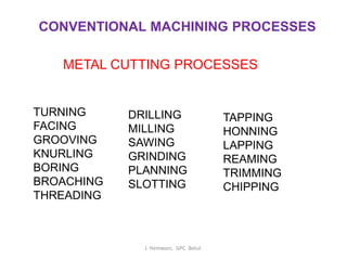
- 1. CONVENTIONAL MACHINING PROCESSES METAL CUTTING PROCESSES TURNING FACING GROOVING KNURLING BORING BROACHING THREADING DRILLING MILLING SAWING GRINDING PLANNING SLOTTING TAPPING HONNING LAPPING REAMING TRIMMING CHIPPING J. Hemwani, GPC Betul.
- 2. CONVENTIONAL MACHINING PROCESSES METAL FORMING PROCESSES ROLLING, FORGING, EXTRUSION, DRAWING, WELDING, BRAGING SOLDERING, SPINNING, PIERCEING, PUNCHING, BENDING, EMBOSSING J. Hemwani, GPC Betul.
- 3. BORING MACHINE 5:54m https://www.youtube.com/watch?v =QGJ5iKyk-Nc&list=PLO5JJ- e4NcX_1oRnyHTxasz7HvaeFeR8 0&index=5 BROACHING MACHINE12 m https://www.youtube.com/watch?v=6XIQ y6Mon54&list=PLO5JJ- e4NcX_1oRnyHTxasz7HvaeFeR80&ind ex=4 MILLING MACHINE 7:17 m https://www.youtube.com/watch?v=2jc3 HkrHh9s&list=PLO5JJ- e4NcX_1oRnyHTxasz7HvaeFeR80&ind ex=3&t=27s SHAPER MACHINE 1:36 m https://www.youtube.com/watch?v=mF 6G9QyNq1I&list=PLO5JJ- e4NcX_1oRnyHTxasz7HvaeFeR80&in dex=3 TAPPING PROCESS 8:22 m https://www.youtube.com/watch?v=CW SVFjXc138&list=PLO5JJ- e4NcX_1oRnyHTxasz7HvaeFeR80&in dex=6 LATHE MACHINE 10:09 m https://www.youtube.com/watch?v= XXpOwsD0fWM&list=PLO5JJ- e4NcX_1oRnyHTxasz7HvaeFeR80 &index=2&t=34s J. Hemwani, GPC Betul.
- 4. FORGING PROCESS 2:30 m https://www.youtube.com/watch?v=Zg 9UKEJ1Wj8&list=PLO5JJ- e4NcX_1oRnyHTxasz7HvaeFeR80&i ndex=7 HONNING PROCESS 3:25 m https://www.youtube.com/watch?v=TyZ L90po6bg&list=PLO5JJ- e4NcX_1oRnyHTxasz7HvaeFeR80&in dex=8 LAPPING PROCESS 1:20 m https://www.youtube.com/watch?v= 6doeORtYeU4&list=PLO5JJ- e4NcX_1oRnyHTxasz7HvaeFeR80 &index=9 EXTRUSION PROCESS 3:19 m https://www.youtube.com/watch?v=bA EdNrb5xWA&list=PLO5JJ- e4NcX_1oRnyHTxasz7HvaeFeR80&i ndex=10 SOLDERING & BRAZING 2:47 m https://www.youtube.com/watch?v=U8 o3pOuE_f8&list=PLO5JJ- e4NcX_1oRnyHTxasz7HvaeFeR80&i ndex=11 ROLLING PROCESS 2;07m https://www.youtube.com/watch?v=JI M_t9QH8J8&list=PLO5JJ- e4NcX_1oRnyHTxasz7HvaeFeR80&i ndex=12 J. Hemwani, GPC Betul.
- 5. The Need for Advanced Machining Processes Traditional machining processes • Material removal by mechanical means, such as chip forming, abrasion, or micro-chipping The following cannot be done by Traditional (Conventional) processes: • Workpiece strength and hardness very high, >400HB • Workpiece material too brittle, glass, ceramics, heat- treated alloys • Workpiece too slender and flexible, hard to clamp • Part shape complex, long and small hole • Special surface and dimensional tolerance requirements J. Hemwani, GPC Betul.
- 6. Skin panel for missiles and aircraft Turbine blades, nozzles, sheet metal, small- diameter deep holes, dies, thick metallic and nonmetallic parts Advanced machining processes • Utilize chemical, electrical, and high-energy beams J. Hemwani, GPC Betul.
- 7. Classification of Non-Traditional Machining These can be classified according to the source of energy used to generate such a machining action: mechanical, thermal, chemical and electrochemical. Mechanical: Erosion of the work material by a high velocity stream of abrasives or fluids (or both) Thermal (Thermoelectric): The thermal energy is applied to a very small portion of the work surface, causing that portion to be removed by fusion and/or vaporization of the material. The thermal energy is generated by conversion from electrical energy. Electrochemical: Mechanism is reverse of electroplating. Chemical: Most materials (metals particularly) are susceptible to chemical attack by certain acids or other etchants. In chemical machining, chemicals selectively remove material from portions of the workpart, while other portions of the surface are protected by a mask. J. Hemwani, GPC Betul.
- 8. Classification of Non-Traditional Machining Mechanical 1. AJM 2. USM 3. WJM Thermal 1. EDM 2. EBM 3. PBM(PAM) 4. LBM 5. IBM Electrochemical & Chemical 1. ECM 2. ECG 3. CM (Chemical M/cning) 4. CE (Chemical Etching) J. Hemwani, GPC Betul.
- 9. J. Hemwani, GPC Betul. Abrasive Jet Machining
- 10. AJM --- Working Process • A stream of fine grain abrasives mixed with air or suitable carrier gas, at high pressure, is directed by means of a nozzle on the work surface to be machined. • The material removal is due to erosive action of a high pressure jet. . • The process is more suitable when the work material is brittle and fragile. • Abrasive particle impinges on the work surface at a high velocity and this impact causes a tiny brittle fracture and the following air or gas carries away the dislodged small work piece particle. J. Hemwani, GPC Betul.
- 11. J. Hemwani, GPC Betul.
- 12. J. Hemwani, GPC Betul.
- 13. J. Hemwani, GPC Betul.
- 14. Video of ABRASSIVE JET MACHINING 2:42 https://www.youtube.com/watch?v=6ERbGtJFcBw &list=PLO5JJ- e4NcX_1oRnyHTxasz7HvaeFeR80&index=15 2:54 https://www.youtube.com/watch?v=VIb8lDNGWIs&l ist=PLO5JJ- e4NcX_1oRnyHTxasz7HvaeFeR80&index=16 J. Hemwani, GPC Betul.
- 15. J. Hemwani, GPC Betul. AJM --- Advantages ✓ Low capital cost. ✓ Less vibration. ✓ Good for difficult to reach area. ✓ No heat is genera6ted in work piece. ✓ Ability to cut intricate holes of any hardness and brittleness in the material. ✓ Ability to cut fragile, brittle hard and heat sensitive material without damage.
- 16. J. Hemwani, GPC Betul. AJM --- Disadvantages ▪ Low metal removal rate. ▪ Due to stay cutting accuracy is affected. ▪ Parivles is imbedding in work piece. ▪ Abrasive powder cannot be reused.
- 17. J. Hemwani, GPC Betul. AJM --- Applications ➢ For abrading and frosting glass, it is more economical than acid etching and grinding. ➢ For doing hard suffuses safe removal of smears and ceramics oxides on metals. ➢ Resistive coating etc from ports to delicate to withstand normal scrapping. ➢ Delicate cleaning such as removal of smudges from antique documents. ➢ Machining semiconductors such as germanium etc.
- 18. J. Hemwani, GPC Betul. AJM --- Operating Parameters ▪ Medium – Dry air, CO2, N2 – Quantity: 30 liter/min – Velocity: 150-300 m/min – Pressure: 200-1300 KPa • Nozzle – Material: Tungsten carbide or saffire – Stand of distance: 2.54-75 mm – Diameter: 0.13-1.2 mm – Operating Angle: 60° to vertical
- 19. AJM --Process Parameters The process characteristics can be evaluated by judging (1) the MRR, (2) the geometry of the cut, (3) the roughness of the surface produced, and (4) the rate of nozzle wear The major parameters which control these quantities are: 1. The abrasive (composition, strength, size and mass flow rate) 2. The gas (composition, pressure and velocity). 3. The nozzle (geometry, material, distance from and inclination to the work surface). J. Hemwani, GPC Betul.
- 20. AJM --Process Parameters ➢Mainly two types of abrasives are used (1) Aluminum oxide and (2) Silicon carbide. (Grains with a diameter 10-50 microns are readily available) ➢ For good wear action on the surfaces, the abrasive grains should have sharp edges. ➢ A reuse of the abrasive powder is normally not recommended because of a decrease of cutting capacity and clogging of the nozzle orifices due to contamination. ➢ The mass flow rate of the abrasive particles depends on the pressure and the flow rate of the gas. ➢ There is an optimum mixing ratio (mass fraction of the abrasive in the jet) for which the metal removal rate is the highest. ➢ When the mass flow rate of the abrasive increases the material removal rate also increases. J. Hemwani, GPC Betul.
- 21. AJM --Process Parameters ➢The AJM unit normally operates at a pressure of 0.2-1.0 N/mm2 . ➢The composition of gas and a high velocity has a significant impact on the MRR even if the mixing ratio is not changed. ➢The nozzle is one of the most vital elements controlling the process characteristics. ➢The nozzle material should be hard to avoid any significant wear due to the flowing abrasive. [Normally WC (avg. life: 12- 30 hrs.) or Sapphire (Appr. = 300 hrs.) are used] ➢For a normal operation the cross-sectional area of the orifice can be either circular or rectangular and between 0.05- 0.2 mm2 . J. Hemwani, GPC Betul.
- 22. AJM --Process Parameters ➢The nozzle tip distance (NTD) or the stand off distance is a critical parameter in AJM. ➢ The NTD not only affects the MRR from the work surface but also the shape and size of the cavity produced. ➢ As shown in the figure below, when the NTD increases, the velocity of the abrasive particles impinging on the work surface increases due to their acceleration after they leave the nozzle. This increases the MRR. ➢ With a further increase in the NTD, the velocity reduces due to the drag of the atmosphere which initially checks the increase in MRR and then decreases it. J. Hemwani, GPC Betul.
- 23. AJM --Process Parameters ➢The gas propulsion system supplies clean and dry gas (air, nitrogen, or CO 2) to propel the abrasive particles. ➢ The gas may be supplied either by a cylinder or a compressor. ➢ In case of a compressor a filter or a dryer may be used to avoid water or oil contamination to the abrasive powder. ➢The gas should be non toxic, cheap and easily available and should not excessively spread when discharged from nozzle into atmosphere. J. Hemwani, GPC Betul.
- 24. J. Hemwani, GPC Betul. Ultrasonic Machining
- 25. USM --- Process ▪ The basic USM process involves a tool made of a ductile and tough material. ▪ Vibrating with a low amplitude and very high frequency around 20 kHz (Ultra sonic) and a continuous flow of an abrasive slurry in the small gap between the tool and the work piece. ▪ Ultra-sonic are generated by feeding high frequency electrical current to a transducer which converts it to high frequency mechanical vibrations. J. Hemwani, GPC Betul.
- 26. J. Hemwani, GPC Betul. USM --- Process ▪ The tool is pressed against the work piece with a load of few kilograms and fed downwards continuously as the cavity is cut in the work piece. ▪ The vibrations thus, produced are focused to the cutting point by means of horn or a tuned vibration concentrator. ▪ The impact of the hard abrasive grains fractures the hard and brittle work surface, resulting in the removal of the work material in the form of small wear particles. ▪The tool is shaped as the approximate mirror image of the configuration of the cavity desired in the work.
- 27. J. Hemwani, GPC Betul.
- 28. Mechanics of USM The reasons for material removal in an USM process are believed to be: 1. The hammering of the abrasive particles on the work surface by the tool. 2. The impact of free abrasive particles on the work surface. 3. The erosion due to cavitation. 4. The chemical action associated with the fluid used. J. Hemwani, GPC Betul.
- 29. J. Hemwani, GPC Betul.
- 30. J. Hemwani, GPC Betul. https://www.youtube.com/watch?v=HTtnAXrzD4 w&list=PLO5JJ- e4NcX_1oRnyHTxasz7HvaeFeR80&index=17 Video on USM 2:37 m
- 31. J. Hemwani, GPC Betul. USM --- Advantages ✓ It can be used machine hard, brittle, fragile and non conductive material. ✓ No heat is generated in work, therefore no significant changes in physical structure of work material. ✓ Non-metal (having poor electrical conductivity) can very well be machined by USM. ✓It is burr less and distortion less processes hence can be adopted with EDM, ECG, and ECM for better production.
- 32. J. Hemwani, GPC Betul. USM --- Disadvantages ▪ It is difficult to drill deep holes, as slurry movement is restricted. ▪ Tool wear rate is high due to abrasive particles. ▪ USM can be used only when the hardness of work is more than 45 HRC. ▪ USM has very Low Metal Removal Rate.
- 33. J. Hemwani, GPC Betul. USM --- Applications ➢Machining of cavities in electrically nonconductive ceramics. ➢Used for multistep processing for fabricating silicon nitride (Si3N4) turbine blades. ➢Used for machining hard, brittle metallic alloys, semiconductors, glass, ceramics, carbides etc. ➢Used for machining round, square, irregular shaped holes and surface impressions. ➢Used in machining of dies for wire drawing, punching and blanking operations
- 34. USM -- Abrasive Slurry ❖ The most common abrasives are Boron Carbide (B4C), Silicon Carbide (SiC), Corrundum (Al2O3), Diamond and Boron silicarbide. ❖ Diamond dust is used only for cutting daimond and rubies. ❖ Water is the most commonly used fluid although other liquids such as benzene, glycerol and oils are also used. Summary J. Hemwani, GPC Betul.
- 35. USM -- Process Parameters The important parameters which affect the process are the: 1. Frequency: With an increase in frequency of the tool head the MRR increases. The frequency used is 15-30 kHz 2. Amplitude: When the amplitude of the vibration increases the MRR is expected to increases. The amplitude of vibration is kept as 25-100 µm 3. Feed force: We already said that with an increase in Feed Force, the MRR tends to increase. But at higher values MRR decreases due to grain crushing J. Hemwani, GPC Betul.
- 36. USM -- Process Parameters 4. Hardness ratio of the tool and the work-piece, affects the MRR. Apart from hardness the brittleness of the work material also affects the MRR. 5. Grain size: With increase in mean grain diameter the crushing hence MRR increases. Generally the grit size of 100-800 of abrasive is used 6. Concentration: Concentration of the abrasives directly controls the number of grains producing impact per cycle. MRR is proportional to C1/4 so after C rises to 30% MRR increase is not very fast. J. Hemwani, GPC Betul.
- 37. USM -- Process Parameters 7. Viscosity: With increase in viscosity of the slurry the MRR decreases. 8. Surface finish: The surface finish generally decrease with increase in grain size. 9. Concentration: Concentration of the abrasives directly controls the number of grains producing impact per cycle. MRR is proportional to C1/4 so after C rises to 30% MRR increase is not very fast. J. Hemwani, GPC Betul.
- 38. J. Hemwani, GPC Betul.
- 39. J. Hemwani, GPC Betul.