Unijunction transistor (ujt)

A unijunction transistor (UJT) is a three-lead electronic semiconductor device with only one junction that acts exclusively as an electrically controlled switch. The UJT is not used as a linear amplifier. It is used in free-running oscillators, synchronized or triggered oscillators, and pulse generation circuits at low to moderate frequencies (hundreds of kilohertz). It is widely used in the triggering circuits for silicon controlled rectifiers. The low cost per unit, combined with its unique characteristic, have warranted its use in a wide variety of applications like oscillators, pulse generators, saw-tooth generators, triggering circuits, phase control, timing circuits, and voltage- or current-regulated supplies.[1] The original unijunction transistor types are now considered obsolete, but a later multi-layer device, the programmable unijunction transistor (PUT), is still widely available.

Recommended
More Related Content
What's hot
What's hot (20)
Similar to Unijunction transistor (ujt)
Similar to Unijunction transistor (ujt) (20)
More from Ishwar Bhoge
Recently uploaded
Recently uploaded (20)
Unijunction transistor (ujt)
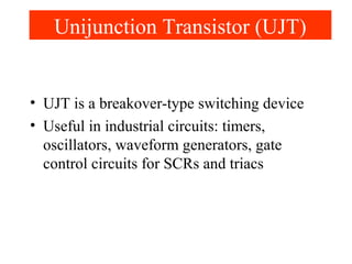
- 1. Unijunction Transistor (UJT) • UJT is a breakover-type switching device • Useful in industrial circuits: timers, oscillators, waveform generators, gate control circuits for SCRs and triacs
- 2. • Is a special transistor that has two bases and one emitter • Has two states: completely on or completely off • Part of thyristor family which include SCR, triac, and diac P Unijunction Transistor (UJT) Lightly-doped Heavily-doped
- 3. • UJT consists of a bar of N-type silicon material (lightly-doped) and a small amount of diffused P-type material (heavily-doped) • An emitter terminal E is connected to the P material to form the PN junction • Two paths for current flow: B2 to B1; E to B1 • Normally current does not flow in either path until Emitter voltage is about 10 volts higher than B1 voltage Unijunction Transistor (UJT)
- 4. • When a voltage, called standoff voltage VP, applied to the emitter is about 10 volts higher than the voltage applied to B1 , UJT turns on and current flows through the B2- B1 path and from the emitter-B1 path UJT Operation
- 5. • Current will continue to flow through the UJT until the voltage applied to the emitter drops to a point that is about 3 volts higher than the voltage applied to B1 Common UJT circuit Pulse produced by capacitor discharge UJT Operation
- 6. • When emitter voltage drops to this point, the UJT will turn off and will remain off until the voltage applied to the emitter again reaches a level about 10 volts higher than the voltage applied to B1 UJT Operation
- 7. • Since the N-type silicon bar is lightly- doped, it has a high resistance and can be represented by two resistors: UJT CHARACTERISTICS B2 B1 E RB2 RB1
- 8. • Resistor RB1is shown as a variable resistor • Its ohmic value depends on the amount of emitter current flowing • The internal resistance ratio of RB1 to RB2 is called the intrinsic standoff ratio, η (eta) • η = UJT CHARACTERISTICS RB1 RB1 + RB2
- 9. • The amount of emitter voltage required to switch the UJT on is called the standoff voltage, VP • It is found be multiplying the applied voltage VBB, by η • VP = ηVBB + VF • VF is the P-N junction forward-voltage drop UJT CHARACTERISTICS
- 10. • When VP is reached, the UJT latches in the conducting state and current flows between E and B1 • The UJT is a latching device that will remain in the conducting state as long as the emitter current remains above a minimum value called the holding current • RB1 varies as a function of the emitter current • As emitter current increases, RB1 decreases UJT CHARACTERISTICS
- 11. • VP is the peak voltage, VV is the valley voltage UJT CHARACTERISTICS UJT CHARCTERISTIC CURVE
- 12. • The UJT appears to the ohmmeter as a connection of two resistors connected to a diode as above • Positive lead of ohmmeter is connected to emitter, a diode junction from emitter to B1 or B2 is seen • Reversing leads we have reverse bias, no continuity Testing the UJT
- 13. Some Packages and Terminal Identification