Probe And Revealing Faults In Three Phase System.
•
0 likes•1 view

https://www.irjet.net/archives/V9/i6/IRJET-V9I6165.pdf

Recommended
Recommended
More Related Content
Similar to Probe And Revealing Faults In Three Phase System.
Similar to Probe And Revealing Faults In Three Phase System. (20)
More from IRJET Journal
More from IRJET Journal (20)
Recently uploaded
Recently uploaded (20)
Probe And Revealing Faults In Three Phase System.
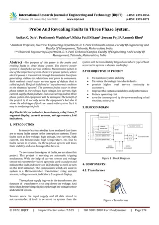
- 1. International Research Journal of Engineering and Technology (IRJET) e-ISSN: 2395-0056 Volume: 09 Issue: 06 | Jun 2022 www.irjet.net p-ISSN: 2395-0072 © 2022, IRJET | Impact Factor value: 7.529 | ISO 9001:2008 Certified Journal | Page 974 Probe And Revealing Faults In Three Phase System. Aniket C. Daiv1, Prathmesh Wadekar2, Nikita Patil Nikam3 , Jeevan Patil4, Ramesh Khot5 1Assistant Professor, Electrical Engineering Department, D. Y. Patil Technical Campus, Faculty Of Engineering And Faculty Of Management, Talsande, Maharashtra, India. 2345Electrical Engineering Department, D. Y .Patil Technical Campus, Faculty Of Engineering And Faculty Of Management, Talsande, Maharashtra, India ---------------------------------------------------------------------***--------------------------------------------------------------------- Abstract -The purpose of this paper is the probe and reveling faults in three phase system. The electric power system is classified in various sections. Transmission system is one of the important system of electric power system, where electric power is transmitted through transmission lines from generating stations to substations and given to consumers. Both methods could occur various types of defects that is called as fault. The fault is defined as” any abnormalcondition in the electrical system”. The common faults occur in three phase system is low voltage, high voltage, low current, high current, supply phase fault etc. Due to occurring fault in three phase system, the equipment will be damaged. The benefit of the project is, it not only saves the equipment’s but also it shows the which type of faults occurred in the system. So, it is easy to analyzing the fault. Key Words: Microcontroller, transformer, relay,timer,7 segment display, current sensors, voltage sensors, Led indicators. 1. INTRODUCTION In most of various studies have analyzed that there are so many faults occurs in the three phase systems. These faults such as low voltage, high voltage, low current, high current, low temperature, high temperature, etc. Due to faults occurs in system, the three-phase system will loses their stability and also damages the devices. To overcome these types of faults, we are done this project. This project is working on automatic tripping mechanism. With the help of current sensor and voltage sensor microcontroller-based system is used to analyze and indicate the fault and shows on LED display as well as turn on the LED indicator. The components which are used in system is a Microcontroller, transformer, relay, current sensors, voltage sensors, indicators, 7-segment display. Three phase supply is given to the transformer. the function of transformer is to step down the voltage. And these step down voltage is passesthroughthe voltagesensor and current sensor. Sensors sence the input supply and all data stored in microcontroller, if fault is occurred in system then the system will be immediately tripped and which type of fault occurred in system is shown on display. 2.THE OBJECTIVE OF PROJECT To maintain system stability To reduce the outage time due to faults provide higher level service continuity to customers. Improve the system availability and performance Reduce operating cost save the time required by the crew searching inbad weather, noisy area 3. BLOCK DIAGRAM Figure 1 : Block Diagram 4. COMPONENTS : 4.1. Transformer Figure: - Transformer
- 2. International Research Journal of Engineering and Technology (IRJET) e-ISSN: 2395-0056 Volume: 09 Issue: 06 | Jun 2022 www.irjet.net p-ISSN: 2395-0072 © 2022, IRJET | Impact Factor value: 7.529 | ISO 9001:2008 Certified Journal | Page 975 Transformer is a static device. It is used to step upand stepdown the supply voltage without change infrequency of alternating current circuit. Transformer works on two basic principle which is Faraday’s low of Electromagnetic induction and another is mutual induction. Thereare mainly two coils, primary coil andsecondarycoil onthetransformer core. In that project transformer is used to step down the voltage. 4.2. Microcontroller Figure:-Microcontroller Microcontroller is a compact integratedcircuit whichis designed to control a particular operation in embedded system. A microcontroller consists of processor, input/output and memory peripherals and all these peripherals include on a single chip. In this project nuvotun microcontroller is used. It is used to stored the all data given from voltage sensor unit and current sensor unit. It includes the set of programming which is used to identifying the which type of fault is occurred and operating the whole project circuit. 4.3. Current Sensor Unit It is a device that determine and transform current easily assessable output voltage.it is proportional to the current through the path. Current sensor unit is used in that projectbecauseitis sense the supply current. Collecting the information about supply and fed to the microcontroller. 4.4. Voltage Sensor Unit Voltage sensor is used to calculate and observe the voltage of supply. It can be determine AC and DC voltage level. Capacitive voltage sensor, Resistive voltage sensor these are mainly types of the sensor. The main function of the voltage sensor unit in that project is to sensing the supply voltage and collecting information about supply . And given tothemicrocontroller. 4.5. 7-Segment Display Figure:- 7-Segment Display. 7-segment display is the display device and it can display the information in the form of decimal number or text.it consist of seven LED arrange in seven segment. The common cathode and common anode is the type of the 7- segment display. Which type of fault occurs in the three-phase system is shown on 7-segment display as well as is shows the value of input current and voltage. 4.6.Relay Figure :-Relay Relay is act like switch. It is electromechanically device. It is used to make or break the circuit connection. Relay is consisting of flexible moving mechanical part.And it can be controlled with the help of electromagnet. When fault is occurred then microcontroller give the signal to relay to trip the circuit or break the supply. This is the main function of relay. Relay can control the currents ranging from 2A-30A.
- 3. International Research Journal of Engineering and Technology (IRJET) e-ISSN: 2395-0056 Volume: 09 Issue: 06 | Jun 2022 www.irjet.net p-ISSN: 2395-0072 © 2022, IRJET | Impact Factor value: 7.529 | ISO 9001:2008 Certified Journal | Page 976 4.7.LED’s Figure :-LED's LED means light emitting diode. It is a semiconductor light source that emits lights. In this project, six LED’s are used. It is used when the fault is detecting that time LED will be glow. EachLEDshows the different fault in the system. 5. WORKING To run this project, it requires a supply. The main supply is 440 volts. In this project transformer is used to step down the voltage. The transformer is step down the supply voltage to 18 volt and fed to the project circuit. The microcontroller required 2.2v -5.5volt operating voltage. In this project relay is operated at 12volt supply.Theoperating voltage of 7-segment display is 1.8 volts for normal brightness. It is voltage drop acrosstheLED’sdiodejunction. Firstly, we have required to set the values of voltage, current, dry run current, etc. For this, at the time of power is off that is supply is not given to the system; we canpressand hold the set switch and turn on the supply to the system. Now release and unhold the set switch.Thesettingofsystem is displayed on the 7- segment display. Set the higher and lower values of voltage and current respectively also set the dry run current with the help ofswitchincrementandswitch decrement switch. At normal condition , when power on, the supply current is given to the project circuit. The supply is passes through the current and voltage sensors. The currentsensor senses the supply current as well asvoltagesensorissensing the voltage supply and output of the current and voltage sensor is fed to the microcontroller. In Microcontroller, the value of voltage and current is fixed in microcontroller program using set switch of project. Microcontroller is analyzing the input supply voltage as well as supply current and comparing to the setted voltage and current. At normal condition there is no fault that means supply current and voltage is in between range of setted values of current and voltage so no fault is occurred so the 7-segment display showing the input voltage and current on the display. At faulty condition, when the power is on, supply is transmitted to the project circuit, current and voltage sensors sense the supply voltage and current respectively and feding to microcontroller. Microcontrolleranalyzingthe data. If the setted value of current and voltage is not similar to the supply current and voltage then the microcontrolleris detecting the which type of fault is occurred in the system and it send command to the relay to trip the circuit. Relay check the microcontroller command and immediately trip the circuit. Simultaneously microcontroller send command to the 7- segment display to display the which type of faultis occurred and this fault is showing on the 7- segmentdisplay. And turn on the LED. For example, high supply voltage is passing through the circuit that time voltage sensor sense the supply voltage. It analyzing the input supply that is input supply voltage is high than set voltage then this data is given to the microcontroller. Microcontroller detecting the fault and sending the command to relay to trip the circuit as well as sending the command to 7-segment display to show the which type of fault is occurred. Relay trip the circuit and 7- segment display showing the fault name as well as turn on the LED. In this project we can detecting the various faults. These are high voltage, low voltage, high current, low current, dry run fault, supply phase fault, supply reversal fault. These faults are detecting in our project. Whenever dry run fault is occurred then the system is given 60 minutes to consumer to clearing the fault. After 60 minutes the system will again turn ON automatically. 5.1. Hardware of Project Figure :- Hardware of Project
- 4. International Research Journal of Engineering and Technology (IRJET) e-ISSN: 2395-0056 Volume: 09 Issue: 06 | Jun 2022 www.irjet.net p-ISSN: 2395-0072 © 2022, IRJET | Impact Factor value: 7.529 | ISO 9001:2008 Certified Journal | Page 977 6. RESULT Sr. No. Voltage Range in Volt Current Range in Amp. 7-segment display LED status 1 415 V 15 A Value of Supply voltage and current All LED is OFF 2 Above 460 V 14 A OVF (Over voltage fault) L1 is ON 3 Below 400 V 16 A UVF (Under voltage fault) L2 is ON 4 407 V Above 20 Amp OCF (Over current fault) L3 is ON 5 415 V Below 10 amp UCF (Under current fault) L4 is ON 6 415 V Below 13 Amp DRF (Dry run fault) L5 is ON 7) In case of phase is reserved then the phase reversal fault is occurred. ’SPF’ that is supply phase fault this message is shown on the 7- segment display as well as L6 LED is turn ON. 7. FUTURE SCOPE: - 1) In the upcoming years GSM service can be added in that system to know the consumer, when fault is occurred and which fault is occurred. 2) Now fault is automatically detected through this project but by working on this project we can automatically clear the fault in future. 3) In future we can make a voice call which gives us information about three phase faults. 4) In future , we can added GPS system to finding a proper fault location 8. ADVANTAGES 1. We can find the fault easily using this project. 2. We can save the equipment from damage. 3. We can easily analyze the supply current and voltage. 4. It is easy to handle. 5. It is more helpful to consumer. 6. Cost is reliable. 8. CONCLUSION This project shows about the faultdetection.Themain motive to invent this project is to rescue the load equipment from damage. In the transmission system there are various types of faults. In our project we are detecting the six types of faults such as high voltage, low voltage, high current, low current, dry run motor fault, supply phase fault. Above type of fault occurred in the system then the circuit will be tripped automatically. In this project all over activities are controlled by the microcontroller. The working process of the system is introducing in the paper and also practical implementation and result of this project is added in the paper. REFERENCES 1. M. S. Morey, “Microcontroller Based Three Phase Fault Analysis For Temporary And Permanent Fault”, Volume: 2, Issue :01, March 2015. 2. Akshit Sharma, “Fault Analysis On Three Phase Transmission Lines And Its Detection”, ISSN-2347- 3258, Volume-5, Issue -2(2017)229-233. 3. Prof. Dr .Zahid Hasan Mahmud, “GSM & Microcontroller based Three Phase Fault Analysis System”, ISSN 2278-2763, Volume-6,Issue-1, January 2017. 4. Prof. Vikramsingh R. Parihar, “Automatic Fault Detection In Transmission Lines Using GSM Technology”, ISSN-2321-2004, Vol-6, Issue-4, April 2018. 5. Ms. Priya. D. Duggal and Ms. Indrayani Patle, “FAULT DETECTION BYTHREEPHASETECHNIQUE USING MICROCONTROLLER”, IEJRD - International Multidisciplinary Journal, vol. 5, no. 3, p.5, Apr. 2020. 6. Dhanashree Joshi, “Three Phase Fault Analysis for Temporary And Permanent Fault Based On Microcontroller”, ISSN-2394-4099, Volume-4, Issue-4, 7. “Protection of 3-Phase Distribution Line Fault and Detection of Rise in TemperatureofTransformerby using GSM Technique”, ISSN- 2321-0613, Vol. 6, Issue 04, 2018. 8. “Fault Detection In Three Phase Electrical Distribution system Using Microcontroller”, Volume-v, Issued -x, October -2016.