Toroidal Drive System for Vehicle Transmission Control

A continuously variable transmission (CVT) is a transmission which better fuel efficiency, quieter operation, and a lower mass. Current efforts to reduce the vehicles, fuel consumption in order to protect the environment and save fuel have seen a recent resurgence in CVT research, especially in the automotive allow a continuous variation of the output velocity by adjusting its geometrical configuration. This offers several advantages over traditional transmissions such as industry. The torque of the continuously variable transmission system with friction drive mechanism is transmitted by contacting roller with input and output disks. For the higher transmitted torque, it is necessary to apply large load in order to get higher friction force, which in turn generates severe high stress on the contact surfaces of roller and disks. The 'Toroidal' type CVT system has simple component arrays. This work documents a successfully developed experimental model of a 'Toroidal' continuously variable transmission (CVT) by adjusting its geometrical configuration of CVT design and compared the experimental results of speed, torque and power delivered at the output disc with those obtained by a theoretical.

Recommended
More Related Content
What's hot
What's hot (20)
Viewers also liked
Viewers also liked (9)
Similar to Toroidal Drive System for Vehicle Transmission Control
Similar to Toroidal Drive System for Vehicle Transmission Control (20)
More from ijsrd.com
More from ijsrd.com (20)
Recently uploaded
Recently uploaded (20)
Toroidal Drive System for Vehicle Transmission Control
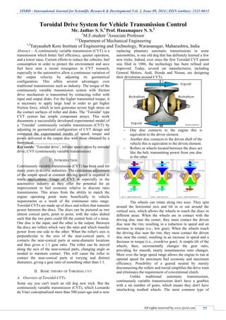
- 1. IJSRD - International Journal for Scientific Research & Development| Vol. 2, Issue 09, 2014 | ISSN (online): 2321-0613 All rights reserved by www.ijsrd.com 77 Toroidal Drive System for Vehicle Transmission Control Mr. Jadhav S. S.1 Prof. Hanamapure N. S.2 1 M.E.student 2 Associate Professor 1,2 Department of Mechanical Engineering 1,2 Tatyasaheb Kore Institute of Engineering and Technology, Warananagar, Maharashtra, India Abstract— A continuously variable transmission (CVT) is a transmission which better fuel efficiency, quieter operation, and a lower mass. Current efforts to reduce the vehicles, fuel consumption in order to protect the environment and save fuel have seen a recent resurgence in CVT research, especially in the automotive allow a continuous variation of the output velocity by adjusting its geometrical configuration. This offers several advantages over traditional transmissions such as industry. The torque of the continuously variable transmission system with friction drive mechanism is transmitted by contacting roller with input and output disks. For the higher transmitted torque, it is necessary to apply large load in order to get higher friction force, which in turn generates severe high stress on the contact surfaces of roller and disks. The „Toroidal‟ type CVT system has simple component arrays. This work documents a successfully developed experimental model of a „Toroidal‟ continuously variable transmission (CVT) by adjusting its geometrical configuration of CVT design and compared the experimental results of speed, torque and power delivered at the output disc with those obtained by a theoretical. Key words: „Toroidal drive‟, infinite speed ratios by toroidal drive, CVT (continuously variable transmission) I. INTRODUCTION Continuously variable transmission (CVT) has been used for many years in diverse industries. The continuous adjustment of the output speed at constant driving speed is required in many applications. Usage of CVT is especially in the automotive industry as they offer the potential for an improvement in fuel economy relative to discrete ratio transmissions. This arises from the ability to match the engine operating point more beneficially to vehicle requirements as a result of the continuous ratio range. Toroidal CVTs are made up of discs and rollers that transmit power between the discs. The discs can be pictured as two almost conical parts, point to point, with the sides dished such that the two parts could fill the central hole of a torus. One disc is the input, and the other is the output. Between the discs are rollers which vary the ratio and which transfer power from one side to the other. When the roller's axis is perpendicular to the axis of the near-conical parts, it contacts the near-conical parts at same-diameter locations and thus gives a 1:1 gear ratio. The roller can be moved along the axis of the near-conical parts, changing angle as needed to maintain contact. This will cause the roller to contact the near-conical parts at varying and distinct diameters, giving a gear ratio of something other than 1:1. II. BASIC THEORY OF TOROIDAL CVT: A. Overview of Toroidal CVTs: Some say you can't teach an old dog new trick. But the continuously variable transmission (CVT), which Leonardo da Vinci conceptualized more than 500 years ago and is now replacing planetary automatic transmissions in some automobiles, is one old dog that has definitely learned a few new tricks. Indeed, ever since the first Toroidal CVT patent was filed in 1886, the technology has been refined and improved. Today, several car manufacturers, including General Motors, Audi, Honda and Nissan, are designing their drivetrains around CVTs. One disc connects to the engine this is equivalent to the driver element. Another disc connects to the driven shaft of the vehicle this is equivalent to the driven element. Rollers or wheels located between the discs act like the belt, transmitting power from one disc to the other. The wheels can rotate along two axes. They spin around the horizontal axis and tilt in or out around the vertical axis, which allows the wheels to touch the discs in different areas. When the wheels are in contact with the driving disc near the center, they must contact the driven disc near the rim, resulting in a reduction in speed and an increase in torque (i.e., low gear). When the wheels touch the driving disc near the rim, they must contact the driven disc near the center, resulting in an increase in speed and a decrease in torque (i.e., overdrive gear). A simple tilt of the wheels, then, incrementally changes the gear ratio, providing for smooth, nearly instantaneous ratio changes. More over the large speed range allows the engine to run at optimal speed for maximum fuel economy and maximum efficiency. Possibility of a geared neutral by merely disconnecting the rollers and toroid simplifies the drive train and eliminates the requirement of conventional clutch. Unlike traditional automatic transmissions, continuously variable transmissions don't have a gearbox with a set number of gears, which means they don't have interlocking toothed wheels. The most common type of
- 2. Toroidal Drive System for Vehicle Transmission Control (IJSRD/Vol. 2/Issue 09/2014/017) All rights reserved by www.ijsrd.com 78 CVT operates on an ingenious pulley system that allows an infinite variability between highest and lowest gears with no discrete steps or shifts. III. CONSTRUCTION The construction of this duplex friction drive is analyzed as a complete solution to variable speed transmission. It consists of following elements A. Motor: Electric motor of following specification is used as the source of power in drive 230 volt, 50Hz, 0.5 Amp Power =50 watt (1/15HP) Speed= 0 to 9000rpm TEFC construction Commutator Motor B. Input Shaft: Input shaft is a high grade steel (EN 36) construction coupled to motor at one end and keyed to the input friction bowl at the other. It is held in heavy duty ball bearing (6204) at the casing. C. Input Friction Bowl: Input friction bowl is similar to friction disc, but is modified in construction that a spherical recess is turned on the face of this disc whose inner surface serves as the friction surface. This friction bowl drives the friction discs at the two ends held between swiveling forks. D. Friction Disk A pair of friction disk lined with friction material on the circumferential face is mounted on respective swiveling forks. A bronze bushing is placed between the rollers and fork pin to minimize frictional losses and wear. E. Swiveling Forks Swiveling forks are holding members that house the friction disks. These forks can be swiveled about their axes to permit angular disposition of the disks with respect to friction bowl axes forks are held in bush bearings mounted in the casing. The forks also carry driving pinions that enable to rotation of the forks to desired angle. F. Output Friction Bowl Output friction bowl is a driven member made of aluminium similar to the input friction bowl. It is keyed to the output shaft. G. Output shaft Output shaft is a high grade steel (EN36) which is keyed to output friction bowl at one end and to the load at the ether end. It is housed in the heavy duty ball bearing (6204) housed in the casing. IV. MECHANICAL DESIGN In mechanical design the components are listed down and stored on the basis of their procurement in two categories, Design parts Parts to be purchased In mechanical design at the first stage selection of appropriate material for the part to be designed for specific application is done. A. Design of Input Shaft: 1) Material Selection: ASME code for design of shaft Since the loads on most shafts in connected machinery are not constant, it is necessary to make proper allowance for the harmful effects of load fluctuations According to ASME code permissible values of shear stress may be calculated form various relation. Using ASME code of design; Allowable shear stress= τall τall is given stress ; τall = 0.30 × 𝝈yd = 0.30 × 700 =210 N/mm2 𝝈yd = Yield strength. τall = 0.18 × 𝝈ut = 0.18 × 900 = 162 N/mm2 𝝈ut = Ultimate tensile strength. Considering minimum of the above values; τall = 162 N/mm2
- 3. Toroidal Drive System for Vehicle Transmission Control (IJSRD/Vol. 2/Issue 09/2014/017) All rights reserved by www.ijsrd.com 79 As we are providing Keyway on shaft, Reduce above value by 25%. τall = 0.75 × 162 = 121.5 N/mm2 2) To calculate input torque: Power = 2ΠNT/60 T = (60×P)/2ΠN T = (60×50)/(2ΠN) Assuming operation speed = 900 rpm. T= (60×50)/ (2Π×900) T = 0.530N.m Considering 100 % overload; Tdesign= 2 T = 1.06N-m Tdesign = 1.06N-m 3) Check for torsional shear failure of shaft. Assume diameter of shaft = 16 mm Tmax= maximum twisting moment. Tmax=Tdesign = design torque on spindle Tdesign= (π/16) × τact d3 τact= τmax =(16 × T) / π × d3 τact= (16 × 1.06 ×103 ) / π × 163 τact= 1.31 N/mm2 As τact < τall Actual shear stress on shaft is less than allowable shear stress on shaft. Shaft is safe under pure tensional load B. Design of Friction Bowl Hub: - Friction bowl hub can be considered to be a hollow shaft subjected to torsional load. 1) Material selection Designation Ultimate Tensile strength N/mm2 Yield strength N/mm2 aluminium 385 275 As Per ASME Code; τmax = 69.3 N/mm2 2) Check for torsional shear failure:- T= ((Π× τact.)/16)×((Do 4 -Di 4 )/Do) 1.06×103 = ((Π× τact)/16)×((504 -404 )/50) τact= 0.0731 N/mm2 As τact < τall Hub is safe under torsional load. 3) Design of roller base: - Roller base can be considered to be a hollow shaft subjected to torsional load. 4) Material selection Designation Ultimate Tensile strength N/mm2 Yield strength N/mm2 EN 24 800 680 As Per ASME Code; τmax = 108 N/mm2 C. Check for torsional shear failure:- τ = (16×Td)/[(Π×Do 3 ) ×(1-C4 )] Here C= Di/DO τact= (16× 1.06×103 )/[( Π×243 ) ×(1-0.1332)] τact = 0.401 N/mm2 As; τact <τall Roller base is safe under torsional load. V. TEST & TRIAL ON TOROIDAL CVT To conduct trial on Orbital Mechanism to determine Torque vs. speed characteristics Power vs. speed characteristics In order to conduct trial, a Dynobrake pulley cord, weight pan are provided on the output shaft. A. Input Data: 1) Drive Motor AC230 Volt 0.5 Amp, 50 watt 50 Hz, 0 to 9000 rpm TEFC COMMUTATOR MOTOR 2) Diameter (Effective) of Dynobrake pulley = 25 mm. B. Procedure: Start motor by turning electronic speed variator knob. Let mechanism run & stabilize at certain speed (say 850 rpm) Place the pulley cord on Dynobrake pulley and add 400 gm. weight into, the pan, note down the output speed for this load by means of tachometer. Add another 200 gm. wt. & take reading. Tabulate the readings in the observation table Plot Torque vs. speed characteristic Power vs. speed characteristic VI. OBSERVATION TABLE During Increase Ratio WEIGHT (gm) SPEED rpm 1. 400 1530 2. 600 1520 3. 700 1400 4. 800 1200 During Decrease Ratio 1 400 400 2. 600 380 3. 700 350 4. 800 300 During Equal Ratio 1 400 790 2 600 780 3 700 700 4 800 600 Table No 7.2.1: Observations. VII. SAMPLE CALCULATIONS At Equal ratio (AT 0.6 kg Load) A. Output Torque To/p = Weight in pan x Radius of Dynobrake Pulley To/p = (0.6 x 9.81) x 25 To/p =147.15N.mm To/p=0.147 N.m B. Input Torque: P= (2πNT/60)=(2x3.14x9000xT)/60 50= (2x3.14x9000xT)/60 T= 0.05307Nm (motor torque)
- 4. Toroidal Drive System for Vehicle Transmission Control (IJSRD/Vol. 2/Issue 09/2014/017) All rights reserved by www.ijsrd.com 80 Now, torque at input pulley=(motor torque x reduction ratio) Ti/p = (0.05307x3.6) =0.1910 Nm C. Input Power: (Pi/p) Pi/p = (2 N Ti/p/60) Pi/p = (2 x x 850x0.1910/60) Pi/p = 17 watt D. Output Power :-( Po/p) Po/p = (2 NTo/p//60) Po/p = (2×Π×780×0.147)/60 Po/p = 12.001 watt. E. Efficiency: = (output power/input power) = (12.001/17) x 100 = 70.59 % VIII. RESULT TABLE A. Result during Increase Ratio SR N O LOA D (gm) SPEE D (rpm) TORQU E (N.M) POWE R (watt) Efficienc y (%) 1. 400 1530 0.0981 15.70 47.38 2. 600 1520 0.14715 23.38 70.54 3. 700 1400 0.171 25.05 75.58 4. 800 1200 0.1962 24.64 74.33 IX. GRAPHS Speed vs. Torque Speed vs Power Speed vs Efficiency X. PHOTO Photo1. Top view of model Photo2. Toroidal model during testing Photo3. Shifter mechanism for ratio change XI. ADVANTAGES CVTs provide a smooth, rapid increase to maximum power. Dual friction drive; i.e. two friction surfaces in contact which increases the torque transmitting capacity. Even wear of rollers; thereby properly balanced power transmission. Easy to maintain proper pressure between the contacts surfaces thereby resulting in trouble free operation. 0 500 1000 1500 2000 15.7 23.38 24.64 25.05 Series1 s p e e d power 0 500 1000 1500 2000 47.38 70.54 74.33 75.58 Series1 s p e e d efficiency
- 5. Toroidal Drive System for Vehicle Transmission Control (IJSRD/Vol. 2/Issue 09/2014/017) All rights reserved by www.ijsrd.com 81 Provide powerful driving performance by continually eliciting high engine power, owing to the fact that minimal power loss occurs during ratio changes. Infinitely variable speed available over a given range. Ease of operation; the speed changes are gradual, without any shock. Singular control Entire range of speeds is covered by a single hand wheel control. Compact size. XII. CONCLUSION As stated earlier in the objective of dissertation, to minimize operational difficulties in the conventional transmission system and also to improve the efficiency of the system Toroidal transmission drive is designed, fabricated and tested satisfactorily. Following are the observations Maximum efficiency of Toroidal drive system is 75.58% during increase speed ratio. In Toroidal transmission system step less speed variation are obtained in the range 300 rpm to 1530 rpm. By decreasing the module size of the gear of shifter mechanism additional speed ratio can be obtained. The system developed here is an open system and the traction fluid is not used, however for the closed system the use of traction fluid will minimize heat generation of the system and improve efficiency. REFERENCES Research Papers [1] R.Fuchs, Y. Hasuda, Y. Rothernbuehler, K. Matsumoto, “Control Concepts of Continuously variable Transmission” JTEKT Engineering Journal English Edition No.1001E (2006). [2] T Dutta-Roy n Zhang, “Effect of a Half Toroidal Continuously Variable Unit on the Dynamics of a Complete Powertrain” Proc. Instn Mech. Engrs Vol. 218 part D:j.automobile engineering. [3] Nibil A.Attia, “Predicting the Life for Half Toroidal Continuously variable Transmission” Information Technology journal 4 (3): 222-227, 2005 ISSN 1812- 5638. [4] QIN Datong, Nabil Abdulla Attia, SHI Wankai, “A Parametric study on the contact stress of Half Toroidal Continuously Variable Transmission” Vol. 2 No.2 Journal ofChongqing University-Eng Ed.December 2003. [5] Leonardo De Novellis, Giuseppe Carbone, Luigi Mangialardi, “Efficiency of the double roller full toroidal variator” Information technology Journal 4(3): 222-227, 2005 ISSN 1812-5638. [6] Shuzou sanda and kisaburo haykawa, “traction Drive Systemand its characteristics as Power” R & D Reviewof Toyota CRDL. Vol. 40 No.3. [7] K. Asano, “Koyo‟s Approach to Continuously Variable Transmission (CVT) for Automobiles” Koyo Engineering Journal English Edition No.164E(2004). Books: [1] Ingenious mechanism for designers & inventors (vol. IV). (By Newell & Horton.) [2] Production technology (by p.c.sharma.) [3] Automobile engineering (by dr. kirpal singh.) [4] Theory of machines. (By r.s.khurmi & j.k. gupta. [5] PSG design data handbook. [6] Design of Machine Elements (by V.B.Bhandari). (Page.no.303, 304, 393, 32,331,333,342). [7] Machine Design (by R.S.khurmi andJ.K.Gupta.