SlideShare a Scribd company logo
1 of 239
Download to read offline
Bearing
By: Nitin Shekapure
N
itin
Shekapure
Bearing is a machine element that have constrained relative motions and used
to reduces friction between moving parts of machine to obtain desired
motion or we can say that the machine elements which are support the
rotating parts of a machine and reduce friction are called bearings.
Due to relative motion between the two parts, there is a friction and wear. In
order to reduce the friction and wear also carries away the heat between two
parts, a lubricant (like vegetable oil, mineral oil, grease) is provided between
the two parts.
Bearing
The main functions of bearings are:
To reduce friction between moving rotatory parts.
To support rotating parts of a machine.
To bear radial and thrust load.
N
itin
Shekapure
Types of bearings
According to design, load and shape there are many types of bearings used in
industries. The mains bearings can be classified as follows.
Friction Bearing
•Solid bearings
•Split bearings
•Self-aligning bush
bearings
•Adjustable slide
bearings
Anti-friction bearing
•Ball bearings
•Single row ball
bearings
•Double row ball
bearing
•Self-aligning ball
bearings
•Angular contact
ball bearings
•Thrust ball
bearings
Roller bearings
•Self-aligning roller
bearings
•Tapered roller
bearings
•Needle roller
bearings
•Cylindrical roller
bearings
•Barrel roller
bearings
•Spherical roller
bearings
According to Load
•Radial or journal
bearings
•Thrust bearings
•Pivot bearings
•Slipper bearings
According to Shape
•Flat shape
bearings
•Round or
cylindrical
bearings
N
itin
Shekapure
Types of bearings
According to the nature of relative motion between the contracting surfaces, the
bearings can be classified as follows.
Bearings
Rolling contact
bearing
Ball
Bearings
Roller
Bearings
Sliding contact or plain or
Journal or Sleeve Bearings
By: Nitin Shekapure
N
itin
Shekapure
N
itin
Shekapure
Bearing Selection Factors
N
itin
Shekapure
Friction bearing
As the name implies, in this bearings the bearing surface is in contact with moving
surface or the shaft which produces more friction. These bearing are made up of cast
iron, bronze, brass and white metal having hollow round shape. Lubricant is used for
slow moving and heavy weighted running on shaft. These bearings to support crack
shaft, rocker arm of IC engine.
Solid bearings
It is a simplest hole made in cast iron to
support the shaft and form running fit. These
are made up of cast iron or bronze in the form
of bush and press-fitted in fabricated or cast
iron housings. This is used for small and light
shafts moving at low speed. A hole is provided
on its face of lubrication.
N
itin
Shekapure
Split bearings
Split bearings are same like solid bearings but
have an arrangement of split. Split bearings are
made in halves and assembled in special
plumber blocks. It has collar on its external
surfaces and also made in two parts as shown
in figure.
Self-aligning bush bearings (Journal Bearing)
It consist mainly two parts. The first one is cast
iron block and other is bush. These bearing
bush are made up of brass or any other soft
material in round shape. To protect it from
moving, a screw is fixed at one end and this
screw is fixed half to the bush and half in block.
N
itin
Shekapure
Adjustable slide bearings
It can adjust the tightness between bearings and the
shaft. This type of bearing has provision for wear
adjustment. The bearing is fitted in the tapered hole
of the housing for adjustment of wear. The bearing is
drawn inside by means of a slotted ring nut.
By: Nitin Shekapure
N
itin
Shekapure
Advantages and disadvantages of friction bearings:
Advantages:
• Friction bearings are cheap to produce and have noiseless operation.
• They can be easily machined, occupy small radial space and have vibration
damping properties.
• They can cope with tapped to the foreign matter.
Disadvantages:
• It damages machines.
• It restricts early movement of machine
• It produces a lot of heat energy.
N
itin
Shekapure
Anti-friction bearing
The main purpose of these bearings is to minimize the friction in bearing. Due to this
reason, the speed of an object increases and friction and temperature decreases.
Such bearing have long life. These bearing also sub-divided into following categories.
Single row ball bearings
• These bearing have only one groove cut in outer and inner rings
with the ball in identical line.
• Having high radial load carrying capacity and moderate axial
(thrust) load carrying capacity.
• Most commonly used type of bearing.
Ball bearings
A ball bearing is a rolling element bearing that used ball to maintain the separation
between the bearing races. The width of these bearing is smaller than the bore
diameter or ball. On the basis of load and groove cut, ball bearings are classified in the
following types
N
itin
Shekapure
Components of Ball bearings
N
itin
Shekapure
Races and balls are high carbon chrome steel (to provide resistance to wear) machined
and ground to fine limits of 0.0025 mm, highly polished and hardened.
N
itin
Shekapure
Double row ball bearings
These bearing have two grooves cut in inner and outer
rings lie in two rows of the bearing.
Self-aligning ball bearings
These bearings can withstand with journal loads. These
loads are generally inclined due to shaft misalignment.
These types of bearings have a spherical bore on the
outer race.
N
itin
Shekapure
Angular contact ball bearings
These bearings are designed to take an axial thrust as
well as radial loads.
Thrust ball bearings
These bearings are useful for taking vertical thrust load
but cannot take any radial load. Some special thrust
bearings are available which can also take horizontal
end thrust.
N
itin
Shekapure
Bearing Loads
N
itin
Shekapure
N
itin
Shekapure
Roller bearings
Roller bearings are available with the grooved race in the outer and inner members.
Roller bearings are capable of carrying the journal (radial) loads. It can work with
greater load than ball bearings. To use this bearing, race is required to be locked. On the
basis of uses, roller bearings are classified in following types.
Needle roller bearingsTapered roller bearingsSelf-aligning roller bearings
By: Nitin Shekapure
N
itin
Shekapure
Spherical roller bearingsBarrel roller bearingsCylindrical roller bearings
By: Nitin Shekapure
N
itin
Shekapure
N
itin
Shekapure
Advantages and disadvantages of anti-friction bearings:
Advantages:
• Special shielded bearing does not required lubrication again.
• It is easy to replace.
• It has very long life and has very less friction.
• It easy operates on high speed and required less lubrication.
Disadvantages:
• Initial cost is usually high.
• Greater diameter space required for comparable shaft diameter.
• Dirt, metal chips and so on, entering the bearings can limit their life causing early
failure.
• Lesser capacity to withstand shock
By: Nitin Shekapure
N
itin
Shekapure
MCQ:
64. The function of bearing is
a) To locate two machine parts relative to each other.
b) To permit the relative motion between two parts.
c) To support load.
d) All of the above.
Explanation : Refer Functions of Bearing
N
itin
Shekapure
MCQ:
66. In bearings, due to relative motion, there is a
a) Friction and wear
b) Corrosion
c) Rusting
d) All of the above.
N
itin
Shekapure
MCQ:
68. The commonly used lubricants in bearings is
a) Vegetable oil
b) Mineral oil
c) Grease
d) All of the above.
N
itin
Shekapure
MCQ:
67. The function of lubricant is
a) To reduce the friction and wear
b) To dissipate the heat.
c) To increase the strength of the component
d) Both a and b
N
itin
Shekapure
MCQ:
68. The antifriction bearings means
a) Sliding contact bearings,
b) Rolling Contact bearings.
c) Bush bearings.
d) Journal bearings.
N
itin
Shekapure
MCQ:
69. The following bearing is not an antifriction bearing
a) Single-row deep-groove ball bearing
b) Journal bearing
c) Cylindrical roller bearing
d) Both (b) and (c)
Explanation : The rolling contact bearings are also called antifriction bearings.
Single-row deep-groove ball bearing and cylindrical roller bearing are rolling contact
or antifriction bearings. The journal bearing is sliding contact bearing.
N
itin
Shekapure
MCQ:
70. The rolling contact bearings are also known as
a) Antifriction bearings
b) Friction bearings
c) Journal bearings
d) None of the above
N
itin
Shekapure
MCQ:
71. The rolling contact bearings are also known as
a) Antifriction bearings
b) Friction bearings
c) Journal bearings
d) None of the above
N
itin
Shekapure
MCQ:
72. The bush bearing is a type of
a) Ball bearings
b) Journal bearings
c) Thrust bearings
d) Roller bearings
N
itin
Shekapure
MCQ:
73. Rolling contact bearing can take
a) Radial and axial force
b) Torque
c) Bending moment
d) Radial force, axial force, torque and bending moment
N
itin
Shekapure
MCQ:
74. The rolling contact bearings are classified as:
a) Ball bearings and roller bearings
b) Single-row bearings and Double-row bearings
c) Ball bearings and bush bearings
d) Cylindrical bearings and thrust bearings
N
itin
Shekapure
MCQ:
75. In ball bearings, the following part is stationary:
a) Inner race
b) Outer race
c) Rolling elements
d) None of the above
N
itin
Shekapure
MCQ:
76. In ball bearings, generally:
a) Inner race is rotating and outer race is stationary
b) Both races are stationary
c) Inner race is stationary and outer race is rotating
d) Both races are rotating
N
itin
Shekapure
MCQ:
77. In ball bearings, the relative motion is between:
a) Inner race and shaft
b) Outer race and frame and casing
c) Inner race and outer race
d) None of the above
N
itin
Shekapure
MCQ:
78. In ball bearings, the relative motion between Inner race and outer race
is through
a) Balls and rollers
b) Bush
c) Separator
d) Journal
N
itin
Shekapure
MCQ:
79. Theis not a part of ball bearings
a) Casing
b) Outer ring
c) Inner ring
d) Separator
N
itin
Shekapure
MCQ:
80. The following element is not used in rolling contact bearings
a) Retainer
b) Bush
c) Outer race
d) All of the above
Explanation : The bush is used in sliding contact bearings and not in rolling contact bearings.
N
itin
Shekapure
MCQ:
81. In rolling contact bearings, the balls or rollers are inserted between
a) Moving and moving elements
b) Fixed and moving elements
c) Fixed and fixed elements
d) None of the above
Explanation : In rolling contact bearings, the balls or rollers are inserted
between fixed outer race and moving inner race.
N
itin
Shekapure
MCQ:
82. In ball bearings, the rolling elements are made of
a) Brass
b) Cast iron
c) Hardened steel
d) copper
N
itin
Shekapure
MCQ:
83. In ball bearings, the contact between bearings surfaces is
a) Rolling contact
b) Sliding contact
c) Linear contact
d) All of the above
Explanation : Ball bearing is a type of rolling contact bearing.
N
itin
Shekapure
MCQ:
84. In ball bearing _______ is mounted on the shaft
a) Outer race
b) Inner race
c) Separator
d) Retainer
Imp :Separator and Retainer and cage are same
N
itin
Shekapure
MCQ:
85. In ball bearings, the function of separator is
a) To separate the balls and rollers.
b) To separate inner race and outer race.
c) To separate the rolling elements and space them evenly.
d) To separate the lubricating oil from the shaft
Explanation : All bearings require lubrication
N
itin
Shekapure
MCQ:
86. The nature of contact in ball bearing is
a) Line contact
b) Surface contact
c) Point contact
d) Volume contact
N
itin
Shekapure
MCQ:
87. In ball bearings, the outer race is is
a) Supported in casing
b) Mounted on shaft
c) Supported by bearing
d) Supported by key
N
itin
Shekapure
MCQ:
88. In rolling contact bearings, the shape of rolling elements is
a) Spherical
b) Cylindrical
c) Tapered cylindrical
d) All of the above
Explanation : In rolling contact bearings, the rolling elements used are
spherical rollers, cylindrical rollers or taper rollers.
N
itin
Shekapure
MCQ:
89. The nature of contact in roller bearing
a) Line contact
b) Surface contact
c) Point contact
d) Area contact
N
itin
Shekapure
MCQ:
90. The needle roller bearing is a special type of
a) Cylindrical roller bearing
b) Taper roller bearing
c) Spherical roller bearing
d) None of the above
N
itin
Shekapure
Clutch
By: Nitin Shekapure
N
itin
Shekapure
A clutch is a mechanical device that engages and disengages the
power transmission, especially from driving shaft to driven shaft.
Clutch
In automobile, a gear box is required to change the speed and torque of the vehicle. If
we change a gear, when the engine is engaged with gear box or when the gears are in
running position then it can cause of wear and tear of gears.
To overcome this problem a device is used between gear box and engine, known as
clutch. Clutch is the first element of power train. The main function of clutch is to
engage and disengage the engine to transmission, when the driver need or during
shifting of gear. When the clutch is in engage position, the power flows from the engine
to the wheel and when it is in disengage position, the power is not transmitted.
N
itin
Shekapure
Principle of clutch
The clutch is based on the friction. When two friction surfaces are brought into
contact and pressed, then they are united due to friction force between them. This
is the basic principle of clutch. The friction between these two surfaces depends
on the area of surface, pressure applied upon them and the friction material
between them.
The driving member of a clutch is the flywheel mounted on the engine crankshaft
and the driven member is pressure plate mounted on the transmission shaft. Some
friction plates, sometimes known as clutch plates are kept between these two
members. This whole assembly is known as the clutch.
N
itin
Shekapure
Friction:
Is the resistance to movement exerted by two objects in contact with each other.
There are two basic types of friction, Static and Sliding or Kinetic friction.
Static Friction:
Is the resistance to motion between two stationary objects.
Sliding Friction:
Is the resistance between a moving object and a stationary object.
Coefficient of Friction: The amount of friction between two surfaces is expressed as
the coefficient of friction (COF). It is important to note that the coefficient of friction
changes for different materials and the state of those materials, smooth, rough etc.
Factors that affect friction are:
a) The pressure exerted on the surface.
b) The coefficient of friction between the materials in contact.
c) The surface contact area of the objects.
Changing any of these three factors will change the actual friction between the materials in
contact.
N
itin
Shekapure
Function of clutch:
An automobile clutch has following function:
1. It can be disengaged. This allows engine cranking and permits the engine to
run without delivering power to the transmission.
2. While disengaging it permits the driver to shift the transmission into various
gear according to operating condition.
3. While engaging, the clutch slips momentarily. this provides smooth
engagement and lessens the shock on gears, shaft and other parts of
automobile.
4. While engaging, the clutch transmits the power to the wheel
without slipping, in idea condition.
N
itin
Shekapure
Location of clutch in Automobile
N
itin
Shekapure
Clutches
Positive
Clutch
Gear Tooth
Spiral
Friction
Clutch
Plate or
Disc
Single Plate
Multiple
Plate
Cone Centrifugal
Types (Classification) of Clutch
N
itin
Shekapure
Positive Clutch (Dog clutch)
The positive clutches are used when positive (no slip) drives are
required. These clutches transmit power from the drive shaft to the
driven shaft by the interlocking of jaws or teeth.
They are rarely used as compared to friction clutch.
E.g. jaw clutch, claw clutch, toothed clutch.
N
itin
Shekapure
Square jaw clutch; that is the simplest form of a positive clutch. Jaw
clutch consists of two halves; one of them permanently fastened to the driver
shaft. The other half is movable and is attached to the driven shaft. It can
freely slide axially on the shaft, but cannot turn due to feather key. They can
transmit power in both directions; they are used when it is not necessary to
engage or disengage under load.
N
itin
Shekapure
Spiral jaw clutches are used when it needs to transmit power only in
one direction; it may be left handed or right handed. They are used when
engaging and disengaging while in motion is necessary.
N
itin
Shekapure
Application of positive clutch
They have very limited use. However, they have some application where the
synchronous drive is required.
Advantages and disadvantages of positive clutch
Advantages
• They do not slip.
• They can transmit large torque.
• Develop no heat during engagement and disengagement because of rigid
interlocking (no friction).
Disadvantages
• Engagement of clutch cannot be possible at high speed.
• While starting some relative motion may be required to engage.
Extra:
What are positive drives?
The positive drive means there is no slip, i.e. the input and output have the
same speeds under any conditions.
N
itin
Shekapure
Friction Clutch
They are the most frequently used type of clutch. A friction clutch transmits
power by virtue of friction developed between contacting surface. The friction
surface is typically flat and perpendicular to the axis of rotation. Two or more
surface is pressed together by using compression spring. The friction force is
used to bring the driven shaft to the proper speed gradually without excessive
slipping. The major types of friction clutches are plate clutch, cone
clutch, centrifugal clutch.
Various materials have been used for the disc-friction facings,
including asbestos in the past. Modern clutches typically use compound
organic resin with copper wire facing or a ceramic material.
N
itin
Shekapure
Friction Clutch : It may be
1. Single plate clutch
2. Multi-plate clutch
3. Cone clutch.
Multi-plate clutch can be either wet or dry.
A wet clutch is operated in an oil batch whereas a dry clutch does not
use oil.
Centrifugal clutch.
Semi-centrifugal clutch.
Hydraulic clutch.
Positive clutch.
Vacuum clutch.
Electromagnetic clutch.
N
itin
Shekapure
Single Plate Clutch
• A single plate clutch is commonly used in cars and light vehicles. It has only one clutch
plate which is mounted on the splines of the clutch shaft.
• A flywheel is mounted on the crankshaft of the engine.
• A pressure plate (Driving plate) is connected to the flywheel through the bolts and
clutch springs. It is free to slide on the clutch shaft with the movement of clutch pedal.
• When clutch is in engaged position, the clutch plate (friction plate) remains gripped
between flywheel and pressure plate. Friction linings are provided on both the sides of
clutch plate. On one side clutch plate is in touch with flywheel and on other side with
pressure plate.
• Due to friction on both sides, the clutch plate revolves with engine flywheel.
Therefore, clutch transmits engine power to clutch shaft. Clutch shaft is connected to
transmission (or gear box) of automobile. Thus, clutch transmits power from engine to
transmission system which inturn rotates wheels of engine.
N
itin
Shekapure
When the clutch plate is to be disengaged, the clutch pedal is pressed. Because
of this pressure plate moves back and clutch plate is disengaged from
flywheel. Thus, clutch shaft stops rotating even if engine flywheel is rotating.
In this position, power does not reach the wheels and vehicle also stops
running. Single plate clutch is shown in Figure:
N
itin
Shekapure
Multiplate Clutch
Multi-plate clutch consists of more than one clutch plates. Friction surfaces are
made in case of multi-plate clutch. Due to increased number of friction
surfaces, a multi-plate clutch can transmit large torque. Therefore, it is used in
racing cars and heavy motor vehicles witch have high engine power. The clutch
plates are alternatively fitted with engine shaft and the shaft of gear box.
plates are firmly held by the force of coil springs and they assembled in a drum.
One plate slides in the grooves on the flywheel and the next plate slides on
spines provided on pressure plate. Thus, each alternate plate slides in grooves
on the flywheel and the other on splines of pressure plate. If we take two
consecutive plates, then one has inner and other has outer splines.
N
itin
Shekapure
When the clutch pedal is pressed, the pressure plate moves back against the
force of coil spring, hen the clutch plates are disengaged and engine flywheel
and gear box are decoupled. However, when clutch pedal is not pressed the
clutch remain in engaged position and the power can be transmitted from
engine flywheel to the gear box. This type of clutch has been shown in Figure
below:
N
itin
Shekapure
Cone Clutch
The engine shaft consists of a female cone, the male cone can slide on the clutch
shaft. When the clutch is engaged the friction surfaces of the male cone are in contact
with that of the female cone due to the force of spring. When the clutch pedal is
pressed, the male cone slides against the spring force and the clutch is disengaged.
The only advantage of the cone
clutch is that the normal force acting
on the friction surfaces is greater
that the axial force, as compared to
the single plate clutch in which the
normal force acting on the friction
surfaces is equal to the axial force.
N
itin
Shekapure
Advantages of friction clutch
• Smooth engagement and minimum shock during the engagement.
• Friction clutch can be engaged and disengaged when the machine is running
since they have no jaw or teeth.
• Easy to operate.
• They are capable of transmitting partial power.
• Friction clutch can act as a safety device. They slip when the torque exceeds
a safe value, thus safeguards the machine.
• Frequent engagement and disengagement is possible.
N
itin
Shekapure
MCQ:
91. _______is the mechanical device used to connect or disconnect the
driving shaft from driven shaft at the all of the operator
a) Coupling
b) Clutch
c) Bearing
d) Brake
N
itin
Shekapure
MCQ:
92. If the two shafts rotating at different speeds are connected by a
device, at the will of the operator, to bring them to the same speed, it
is called as
a) Coupling
b) Clutch
c) Bearing
d) Governer
N
itin
Shekapure
MCQ:
93. In automobile, clutch is located
a) Inside gear box
b) Between gear box and propeller shaft
c) Between engine and gear box
d) Between propeller shaft and differential
N
itin
Shekapure
MCQ:
94. The ________is capable of transmitting a partial power from input
shaft to output shaft.
a) Flange coupling
b) Bushed-pin type coupling
c) Clutch
d) None of the above
N
itin
Shekapure
MCQ:
95. In clutch,___________is a desirable property
a) Wear
b) Friction
c) Surface finish
d) Hardness
N
itin
Shekapure
MCQ:
95. In clutch, ___________ is a desirable property
a) Wear
b) Friction
c) Surface finish
d) Hardness
N
itin
Shekapure
MCQ:
96. In friction clutch, increase in coefficient of friction
a) Reduces the efficiency
b) Reduces the power transmitting capacity
c) Increases the power transmitting capacity
d) Both a and b
N
itin
Shekapure
MCQ:
97. The clutches are used in automobiles
a) Line clutch
b) Cone clutch
c) Centrifugal clutch
d) Jaw clutch
N
itin
Shekapure
MCQ:
98. _______ are most commonly used types of clutches in automobile.
a) Cone clutch and centrifugal clutch
b) Single plate clutch and multiple clutch
c) Cone clutch
d) Multiplate clutch and centrifugal clutch
N
itin
Shekapure
MCQ:
99. _______ is a type of frictional clutch
a) Plate clutch
b) Centrifugal clutch
c) Cone clutch
d) All of the above
N
itin
Shekapure
MCQ:
100.In single plate clutch
a) The pressure plate is on driving shaft and friction plate is on driven shaft
b) The friction plate is on driving shaft and pressure plate is on driven shaft
c) The friction plate is on driving as well as driven shaft
d) None of the above
N
itin
Shekapure
MCQ:
101. In single plate clutch
a) The pressure plate is on driving shaft and friction plate is on driven shaft
b) The friction plate is on driving shaft and pressure plate is on driven shaft
c) The friction plate is on driving as well as driven shaft
d) None of the above
N
itin
Shekapure
MCQ:
102. Which of the following statement is incorrect ?
a) Clutch is normally in engaged condition
b) Friction clutch is positive type
c) Springs are used in clutch
d) Single plate clutch is dry type
N
itin
Shekapure
MCQ:
103. Springs are used in
a) Plate clutches
b) Cone clutches
c) Centrifugal clutches
d) All of the above
Explanation : In all friction clutches, helical compression springs are used to
exert axial force between driving and driven plates.
N
itin
Shekapure
MCQ:
104.In friction clutches, the friction plate is also known as
a) Pressure Plate
b) Clutch plate
c) Driving plate
d) All of the above
N
itin
Shekapure
MCQ:
105. In friction clutch, asbestos is used as
a) Insulating material
b) Lubricating material
c) Protective material
d) Friction material
N
itin
Shekapure
MCQ:
106.Single plate clutch is normally
a) Dry type
b) Wet type
c) Grease lubricated
d) Oil lubricated
N
itin
Shekapure
MCQ:
107. In disengaged condition of clutch
a) Driving shaft as well as driven shaft are stationary.
b) Driving shaft as well as driven shaft are rotating
c) Driving shaft is rotating while driven shaft is stationary.
d) Driving shaft is stationary while driven shaft is rotating.
N
itin
Shekapure
MCQ:
108.In clutch, during engagement, the axial force between driving and
driven plates is created by
a) Clutch padal
b) Clutch cable
c) Splined shaft
d) Helical compression spring
N
itin
Shekapure
MCQ:
109.The overall size of ______clutch is large
a) Cone
b) Centrifugal
c) Single plate
d) All of the above
N
itin
Shekapure
MCQ:
110. Which of the following statement is correct ?
a) Single plate clutch is wet type while multi-plate clutch is dry type.
b) Single plate clutch is dry type while multi-plate clutch is wet.
c) Single plate clutch as well as multi-plate clutch are wet type
d) Single plate clutch as well as multi-plate clutch are dry type
N
itin
Shekapure
Brakes
By: Nitin Shekapure
N
itin
Shekapure
A clutch is a mechanical device that engages and disengages the
power transmission, especially from driving shaft to driven shaft.
Brake
In automobile, a gear box is required to change the speed and torque of the vehicle. If
we change a gear, when the engine is engaged with gear box or when the gears are in
running position then it can cause of wear and tear of gears.
To overcome this problem a device is used between gear box and engine, known as
clutch. Clutch is the first element of power train. The main function of clutch is to
engage and disengage the engine to transmission, when the driver need or during
shifting of gear. When the clutch is in engage position, the power flows from the engine
to the wheel and when it is in disengage position, the power is not transmitted.
By: Nitin Shekapure
N
itin
Shekapure
Functions of vehicle braking
There are two main functions of brakes :
1. To slow down or stop the vehicle in the shortest possible time at
the time of need.
2. To control the speed of vehicle at turns and also at the time of
driving down on a hill slope.
By: Nitin Shekapure
N
itin
Shekapure
Principle of vehicle braking
Braking of a vehicle depends upon the static function that acts
between tyres and road surface. Brakes work on the following principle
to stop the vehicle :
“The kinetic energy due to motion of the vehicle is dissipated in the
form of heat energy due to friction between moving parts (wheel or
wheel drum) and stationary parts of vehicle (brake shoes)”.
The heat energy so generated due to application of brakes is dissipated
into air.
Brakes operate most effectively when they are applied in a manner so
that wheels do not lock completely but continue to roll without
slipping on the surface of road.
N
itin
Shekapure
Classification of brakes
On the Basis of Method of Actuation
 Foot brake (also called service brake) operated by foot pedal.
 Hand brake – it is also called parking brake operated by hand.
On the Basis of Mode of Operation
 Mechanical brakes (Drum Brake & Disk (Disc) Brake)
 Hydraulic brakes
 Air brakes
 Vacuum brakes
 Electric brakes.
By: Nitin Shekapure
N
itin
Shekapure
On the Basis of Action on Front or Rear Wheels
 Front-wheel brakes
 Rear-wheel brakes.
On the Basis of Method of Application of Braking Contact
 Internally – expanding brakes
 Externally – contracting brakes.
By: Nitin Shekapure
N
itin
Shekapure
Disk brake (Caliper disk beake)
In a disc brake, the fluid from the master cylinder is forced into a caliper where it
presses against a piston.
The piston in turn squeezes two brake pads against the disc (rotor), which is attached
to wheel, forcing it to slow down or stop.
Disc Brake and Brake of a Bicycle
Similar to a bicycle brake where two rubber
pads run against the wheel rim creating
friction.
But in a disc brake, the brake pads squeeze
the rotor instead of the wheel, and the force
is transmitted hydraulically instead of
through a cable.
N
itin
Shekapure
Drum brake (Internal expanding shoe brake)
The drum brake has a metal brake drum that encloses the brake assembly at each wheel.
Two curved brake shoes expand outward to slow or stop the drum which rotates with
the wheel.
Working:
• Drum brakes work on the same principle as
the disc brakes.
• Shoes press against a rotating surface.
• In this system that surface is called a drum.
• Drum brake also has an adjuster mechanism, an emergency brake
mechanism and lots of springs.
• The shoes are pulled away from the drum by the springs when the brakes
are released.
N
itin
Shekapure
Some more Points
• Most modern cars have disc brakes on front wheels and drum brakes
on rear wheels and some wheels have disc brakes on all four wheels.
• To increase safety, most modern car brake systems are broken into two
circuits, with two wheels on each circuit.
• If a fluid leak occurs in one circuit, only two of the wheels will loose
their brakes and the car will still be able to stop when we press the
break pedal
Application
• Drum brake: Used in automobile vehicles ( trucks, buses, cars, motorcycles,
scooter, etc.
• Disk brake: Used in modern motorcycles and racing cars due to its excellent
control . Also used in conveyers
N
itin
Shekapure
Short notes on miscellaneous Braking systems
Air Brakes
Air brakes are applied by the pressure of compressed air. Air pressure applies force on
brakes shoes through suitable linkages to operate brakes. An air compressor is used to
compress air. This compressor is run by engine power.
Vacuum Brakes
Vacuum brakes are a piston or a diaphragm operating in a cylinder. For application of
brakes one side of piston is subjected to atmospheric pressure while the other is applied
vacuum by exhausting air from this side. A force acts on the piston due to difference of
pressure. This force is used to operate brake through suitable linkages.
Electric Brakes
In electrical brakes an electromagnet is used to actuate a cam to expand the brake shoes.
The electromagnet is energized by the current flowing from the battery. When flow of
current is stopped the cam and brake shoes return to their original position and brakes are
disengaged. Electric brakes are not used in automobiles as service brakes.
N
itin
Shekapure
MCQ:
111. The following mechanical element is meant for absorbing the
kinetic or potential energy of a moving system and converts it into
heat which is finally dissipated to the surrounding:
a) Clutch
b) Brake
c) Spring
d) Flywheel
N
itin
Shekapure
MCQ:
112. _________ brake is not used in vehicles.
a) Band
b) Disk
c) Internal expanding shoe
d) Both a and b
N
itin
Shekapure
MCQ:
113. Disk brake is also known as
a) Drum disk brake
b) Caliper disk brake
c) Internal disk brake
d) Shoe disk brake
N
itin
Shekapure
MCQ:
114. Now a days ______ brakes are used in motor cycle
a) Drum brake
b) Disk brake
c) Pads
d) None of the above
N
itin
Shekapure
MCQ:
115. Racing cars used
a) Drum brakes
b) Disk brakes
c) Band brakes
d) Band and block brakes
N
itin
Shekapure
MCQ:
116. Disk brakes are used in motor cycles due to
a) High torque transmission capacity
b) High power transmission capacity
c) High mechanical efficiency
d) Excellent control
N
itin
Shekapure
MCQ:
117. Disk brakes consists of
a) Shoes
b) Blocks
c) Pads
d) None of the above
N
itin
Shekapure
MCQ:
118. The energy absorb by the brake is
a) Strain energy
b) Kinetic energy
c) Potential energy
d) b or c
N
itin
Shekapure
MCQ:
119. The energy absorb by the brake is dissipated in the from of_____
a) Heat
b) Kinetic energy
c) Potential energy
d) All of the above
N
itin
Shekapure
MCQ:
120. The following mechanical element absorb the power
a) Clutch
b) Spring
c) Flywheel
d) Brake
N
itin
Shekapure
Power Transmission devices
By: Nitin Shekapure
N
itin
Shekapure
Power Transmission devices or drives
• Chain drives
• Gear drives
• The system that is used to transmit power from one mechanical element to
another mechanical element.
• The power transmission and speed reduction between prime mover
(Electric motor, IC engines, Gas turbine, Steam turbines, etc.) and the
driven machine can be achieved by using various transmitting systems.
• In order to achieve a high power to weight ratio, the prime movers are
designed with high operating speeds which are usually higher than required
by the driven machines.
Types of transmitting system
• Belt drives
• Rope drives
By: Nitin Shekapure
N
itin
Shekapure
Factors to select transmission system
• Distance between driver and driven pulley shaft.
• Operational speed.
• Power to be transmitted
By: Nitin Shekapure
N
itin
Shekapure
Belt Drives
By: Nitin Shekapure
N
itin
Shekapure
Belt Drives
• Power is to be transmitted between the parallel shaft.
• Consists of two pulleys over which a endless belt is passed encircling (enclosing)
the both.
• Rotary motion is transmitted from driving pulley to driven pulley.
• As the power is transmitted because of the friction between the belt and pulley
surface, it is not a positive drive and there can be a small percentage of slip.
N
itin
Shekapure
Belt drive is an example of flexible machine element used to transmit power
from one shaft to another. Belts are the cheapest mode of power transmission.
The selection of a belt drive depends upon;
• The direction of belt motion.
• Power to be transmitted.
• The velocity of shaft and Velocity ratio.
• Speed reduction ratio
• The distance between shafts, space available.
• Service conditions.
• Space available
• Shaft layout
Belt Drives
By: Nitin Shekapure
N
itin
Shekapure
If a huge amount of power is to be transmitted, then a single belt may not be
sufficient. In such a case, wide pulleys (for V-belts or circular belts) with a
number of grooves are used. Then a belt in each groove is provided to transmit
the required amount of power from one pulley to another.
Material used for Belts
• Leather belts
• Cotton or fabric belts
• Rubber belt
• Balata belts
By: Nitin Shekapure
N
itin
Shekapure
Types of Belt Drives
The belt drives are usually classified into the following three groups :
1. Light drives: These are used to transmit small powers at belt speeds
upto about 10 m/s, as in agricultural machines and small machine tools.
2. Medium drives: These are used to transmit medium power at belt
speeds over 10 m/s but up to 22 m/s, as in machine tools.
3. Heavy drives: These are used to transmit large powers at belt
speeds above 22 m/s, as in compressors and generators.
By: Nitin Shekapure
N
itin
Shekapure
Types of Belt
Though there are many types of belts used these days, yet the
following are important from the subject point of view
By: Nitin Shekapure
N
itin
Shekapure
Flat Belt
Flat belt is mostly used in the factories and workshops, where a
moderate amount of power is to be transmitted, from one
pulley to another when the two pulleys are not more than 8
meters apart.
V Belt
The V-belt is mostly used in the factories and workshops,
where a moderate amount of power is to be transmitted,
from one pulley to another, when the two pulleys are very
near to each other.
The circular belt or rope is mostly used in the factories and
workshops, where a great amount of power is to be
transmitted, from one pulley to another, when the two
pulleys are more than 8 meters apart.
Circular Belt
N
itin
Shekapure
Types of Flat Belt Drive
1. Open belt drive
2. Crossed or twist belt drive
3. Quarter turn belt drive
4. Belt drive with idler pulleys
5. Compound belt drive
6. Stepped or cone pulley drive
7. Fast and loose pulley drive
By: Nitin Shekapure
N
itin
Shekapure
1. Open belt drive
The open belt drive, is used with shafts arranged parallel and rotating in the
same direction.
N
itin
Shekapure
2. Crossed or twist belt drive
The crossed or twist belt drive, is used with shafts arranged parallel and
rotating in the opposite directions.
N
itin
Shekapure
3. Quarter turn belt drive
The quarter turn belt drive also known as right angle belt drive is used with
shafts arranged at right angles and rotating in one definite direction.
Quarter turn belt drive Quarter turn belt drive with guided pulley
N
itin
Shekapure
4. Belt drive with idler pulleys
A belt drive with an idler pulley is used with shafts arranged parallel and when
an open belt drive cannot be used due to small angle of contact on the smaller
pulley. N
itin
Shekapure
5. Compound belt drive
A compound belt drive is used when power is transmitted from one shaft to
another through a number of pulleys.
N
itin
Shekapure
6. Stepped or cone pulley drive
A stepped or cone pulley drive is used for changing the speed of the driven
shaft while the main or driving shaft runs at constant speed.
This is accomplished by shifting the belt from one part of the steps to the other.N
itin
Shekapure
7. Fast and loose pulley drive
A fast and loose pulley drive is used when the driven or machine shaft is to be
started or stopped when ever desired without interfering with the driving shaft.
A pulley which is keyed to the machine shaft is
called fast pulley and runs at the same speed as
that of machine shaft. A loose pulley runs freely
over the machine shaft and is incapable of
transmitting any power. When the driven shaft is
required to be stopped, the belt is pushed on to
the loose pulley by means of sliding bar having
belt forks.
N
itin
Shekapure
V Belts
• The V-belts are made of fabric and cords moulded in rubber and covered with fabric
and rubber.
• These belts are moulded to a trapezoidal shape and are made endless.
• These are suitable for short drives i.e. when the shafts are at a short distance apart.
• The included angle for the V-belt is usually from 30° – 40°. In case of flat belt drive, the
belt runs over the pulleys whereas in case of V-belt drive, the rim of the pulley is
grooved in which the V-belt runs.
• The effect of the groove is to increase the frictional grip of the V-belt on the pulley and
thus to reduce the tendency of slipping.
• In order to have a good grip on the pulley, the V-belt is in contact with the side faces of
the groove and not at the bottom.
• The power is transmitted by the wedging action between the belt and the V-groove in
the pulley.
N
itin
Shekapure
V Belts
Cross-section of a V-belt Cross-section of a V-grooved pulley
N
itin
Shekapure
Advantages and Disadvantages of V-belt Drive Over Flat Belt Drive
Advantages
1. The V-belt drive gives compactness due to the small distance between the
centres of pulleys.
2. The drive is positive, because the slip between the belt and the pulley
groove is negligible.
3. Since the V-belts are made endless and there is no joint trouble, therefore
the drive is smooth.
4. It provides longer life, 3 to 5 years.
5. It can be easily installed and removed.
6. The operation of the belt and pulley is quiet.
7. The belts have the ability to cushion the shock when machines are started.
8. The high velocity ratio be obtained
9. The V-belt may be operated in either direction with tight side of the belt at
the top or bottom.
N
itin
Shekapure
Advantages and Disadvantages of V-belt Drive Over Flat Belt Drive
Disadvantages
1. The V-belt drive cannot be used with large centre distances.
2. The V-belts are not so durable as flat belts.
3. The construction of pulleys for V-belts is more complicated than pulleys for
flat belts.
4. Since the V-belts are subjected to certain amount of creep, therefore these
are not suitable for constant speed application such as synchronous
machines, and timing devices.
5. The belt life is greatly influenced with temperature changes, improper belt
tension and mismatching of belt lengths.
6. The centrifugal tension prevents the use of V-belts at speeds below 5 m/s
and above 50m/s.
N
itin
Shekapure
Velocity Ratio (Speed Ratio) of Belt Drive
It is the ratio between the velocities of the driver and the follower or driven. It
may be expressed, mathematically, as discussed below :
Let d1 = Diameter of the driver,
d2 = Diameter of the follower,
N1 = Speed of the driver in r.p.m., and
N2 = Speed of the follower in r.p.m.
Length of the belt that passes over the driver, in one minute = Π d1 N1
Similarly, length of the belt that passes over the follower, in one minute = Π d2 N2
Since the length of belt that passes over the driver in one minute is equal to the length
of belt that passes over the follower in one minute, therefore
Π d1 N1 = Π d2 N2
N
itin
Shekapure
Velocity Ratio (Speed Ratio) of Belt Drive
When the thickness of the belt (t) is considered, then velocity ratio,
The velocity ratio of a belt drive may also be obtained as discussed below :
We know that peripheral velocity of the belt on the driving pulley,
and peripheral velocity of the belt on the driven or follower pulley,
N
itin
Shekapure
Velocity Ratio of a Compound Belt Drive
Sometimes the power is transmitted from one shaft to another,
through a number of pulleys. Consider a pulley 1 driving the pulley 2.
Since the pulleys 2 and 3 are keyed to the same shaft, therefore the pulley 1 also drives
the pulley 3 which, in turn, drives the pulley 4.N
itin
Shekapure
N
itin
Shekapure
Rope Drive
• The rope drives are widely used where a large amount of power is to be
transmitted, from one pulley to another, over a considerable distance.
• It may be noted that the use of flat belts is limited for the transmission of
moderate power from one pulley to another when the two pulleys are not
more than 8 meters apart. If large amounts of power are to be transmitted
by the flat belt, then it would result in excessive belt cross-section.
• It may be noted that frictional grip in case of rope drives is more than that
in V-drive.
• One of the main advantage of rope drives is that a number of separate
drives may be taken from the one driving pulley.
• For example, in many spinning mills, the line shaft on each floor is driven by
ropes passing directly from the main engine pulley on the ground floor.
N
itin
Shekapure
Rope Drive
The rope drives use the following two types of ropes :
1. Fiber ropes, and 2. Wire ropes.
The fiber ropes operate successfully when the pulleys are about 60 meters
apart, while the wire ropes are used when the pulleys are up to 150 meters
apart.
N
itin
Shekapure
Chain Drives
By: Nitin Shekapure
N
itin
Shekapure
Chain Drive
• We have seen in belt and rope drives that slipping may occur.
• In order to avoid slipping, steel chains are used.
• The chains are made up of rigid links which are hinged together in order to
provide the necessary flexibility for warping around the driving and driven
wheels.
• The wheels have projecting teeth and fit into the corresponding recesses,
in the links of the chain.
• The wheels and the chain are thus constrained to move together without
slipping and ensures perfect velocity ratio. The toothed wheels are known
as sprocket wheels or simply sprockets. These wheels resemble to spur
gears.
N
itin
Shekapure
Chain Drive
The chains are mostly used to transmit motion and power from one shaft to
another, when the distance between the centres of the shafts is short such as
in bicycles, motor cycles, agricultural machinery, road rollers, etc.
By: Nitin Shekapure
N
itin
Shekapure
Types of power transmission Chain
Of the several types of chains, following two types are mainly use for power
transmission
1. Roller chains 2. Silent or Inverted tooth chains
By: Nitin Shekapure
N
itin
Shekapure
Advantages
Advantages and Disadvantages of Chain Drive Over Belt or Rope Drive
1. As no slip takes place during chain drive, hence perfect velocity ratio is
obtained.
2. Since the chains are made of metal, therefore they occupy less space in
width than a belt or rope drive.
3. The chain drives may be used when the distance between the shafts is less.
4. The chain drive gives a high transmission efficiency (upto 98 per cent).
5. The chain drive gives less load on the shafts.
6. The chain drive has the ability of transmitting motion to several shafts by
one chain only.
N
itin
Shekapure
Disadvantages
Advantages and Disadvantages of Chain Drive Over Belt or Rope Drive
1. The production cost of chains is relatively high.
2. The chain drive needs accurate mounting and careful maintenance.
3. The chain drive has velocity fluctuations especially when unduly stretched
N
itin
Shekapure
Gears
By: Nitin Shekapure
N
itin
Shekapure
Gear
A gear is a wheel with teeth that mesh together with other gears.
Gears change the
• Speed
• Torque (rotational force)
• Direction of rotating axles.
By: Nitin Shekapure
N
itin
Shekapure
History of Gear
Indian history as per our mythological stories is more than 12,000 years old. Since then
people living here have been striving to improve the living conditions. We also know that
earlier people were living in the caves and the doors of the caves were made of granite.
How were these heavy doors opened and closed? They were opened and closed by none
other than a system with gear mechanism, wheel, lever and rope drives. However, the
documented evidence has been lost due to destruction by the invaders and improper
storing of palm leaf literature. The guru Kula method of teaching and passing of the
information from mouth to ear procedure and keeping some of the advances as closely
guarded secret have resulted in poor dissemination of the knowledge and
documentation. But, the knowledge of gears has gone from India to east through some
of the globe trotters from China as back as 2600 years BC. They have used the gears then
ingeniously in chariots for measuring the speed and other mechanisms. Primitive gears
shown in figure on next slide were first used in door drive mechanism in temples and
caves, and water lifting mechanisms 2600 B.C. in India and elsewhere.
N
itin
Shekapure
Aristotle in the fourth century B.C. mentions in his writings that gears were being used
very commonly in many applications. Classical origin of worm gearing was made by
Archimedes 287-212 B.C. Vitruvius a military engineer in his writing in 28 B.C. has described
a number of gear applications
Primitive gears made of wood Water wheel and grain mill described by
Vitruvius 40 B.C
N
itin
Shekapure
Gear - Purpose
Sports cars go fast (have speed) but cannot pull any weight.
Big trucks can pull heavy loads (have power), but cannot go fast.
Gears increase or decrease the power or speed.
By: Nitin Shekapure
N
itin
Shekapure
Gears are toothed members which transmit power / motion
between two shafts by meshing without any slip. Hence, gear
drives are also called positive drives. In any pair of gears, the
smaller one is called pinion and the larger one is called gear
immaterial of which is driving the other.
When pinion is the driver, it results in step down drive in which
the output speed decreases and the torque increases. On the
other hand, when the gear is the driver, it results in step up drive
in which the output speed increases and the torque decreases.
The profile of gear tooth is either involute or cycloid
Gears
N
itin
Shekapure
Gears are most commonly used for power transmission
They can be applied between two shafts which are
• Parallel
• Collinear
• Perpendicular and intersecting
• Perpendicular and nonintersecting
• Inclined at any arbitrary angle
Gears
N
itin
Shekapure
Classification of Gears
Gears are classified according to the shape of the tooth pair and
disposition into
• Spur
• Helical
• Double helical
• Straight bevel
• Spiral bevel
• Worm and spiral gears
By: Nitin Shekapure
N
itin
Shekapure
Spur Gears
• Spur gears have their teeth parallel to the axis.
• They are used for transmitting power between two parallel shafts.
• They are simple in construction, easy to manufacture and cost less.
• They have highest efficiency and excellent precision rating.
• They are used in high speed and high load application in all types of trains
and a wide range of velocity ratios.
• Hence, they find wide applications right from clocks, household gadgets,
motor cycles, automobiles, and railways to aircrafts.
• Spur gear pair can be used for reduction ratio up to 6:1
• The efficiency of spur gear is high (96 % to 99 %)
N
itin
Shekapure
Helical Gears
• Helical gears are used for parallel shaft drives.
• They have teeth inclined to the axis as shown in Figure
• Hence for the same width, their teeth are longer than spur gears and have
higher load carrying capacity.
• Their contact ratio is higher than spur gears and they operate smoother and
quieter than spur gears.
• Their precision rating is good.
• They are recommended for very high speeds and loads.
• Thus, these gears find wide applications in automotive gearboxes.
• Their efficiency is slightly lower than spur gears.
• The helix angle also introduces axial thrust on the shaft.
N
itin
Shekapure
Helical Gears
N
itin
Shekapure
Double Helical Gear or Herringbone Gear
• Double helical or Herringbone gears used
for transmitting power between two parallel shafts.
• They have opposing helical teeth with or without a gap depending on
the manufacturing method adopted.
• Two axial thrusts oppose each other and nullify.
• Hence the shaft is free from any axial force.
• Though their load capacity is very high.
• Manufacturing difficulty makes them costlier than single helical gear.
• Their applications are limited to high capacity reduction drives like that
of cement mills and crushers.
N
itin
Shekapure
Double Helical Gear or Herringbone Gear
By: Nitin Shekapure
N
itin
Shekapure
Internal Gear
• Internal gears are used for transmitting power between two parallel shafts.
• In these gears, annular wheels are having teeth on the inner periphery.
• This makes the drive very compact
• In these drives, the meshing pinion and annular gear are running in the same
direction Their precision rating is fair.
• They are useful for high load and high speed application with high reduction
ratio.
• Applications of these gears can be seen in planetary gear drives of
automobile automatic transmissions, reduction gearboxes of cement mills,
step-up drives of wind mills.
• They are not recommended for precision meshes because of design,
fabrication, and inspection limitations.
N
itin
Shekapure
Internal Gear
Diwabus transmission (Voith) with internal gear
N
itin
Shekapure
Rack and Pinion
• Rack is a segment of a gear of infinite diameter.
• The tooth can be spur as in Fig. 1 or helical as in Fig 2
• This type of gearing is used for converting rotary motion into translatory
motion or visa versa.
Fig 1 Fig 2
By: Nitin Shekapure
N
itin
Shekapure
Typical example of rack and pinion applications are shown below
Rack and Pinion
Lathe carriage drive mechanism
showing rack and pinion arrangement
Radial drilling machine spindle
movement with rack and pinion
arrangement
N
itin
Shekapure
Bevel Gear
Straight Bevel Gear
• Straight bevel gears are used for transmitting power between intersecting
shafts.
• They can operate under high speeds and high loads.
• Their precision rating is fair to good. They are suitable for 1:1 and higher
velocity ratios and for right-angle meshes to any other angles.
• Their good choice is for right angle drive of particularly low ratios.
• Wide application of the straight bevel drives is in automotive differentials,
right angle drives of blenders and conveyors.
• A typical application of straight bevel used in differential application.
N
itin
Shekapure
Bevel Gear Straight Bevel Gear
Differential of an Automobile
By: Nitin Shekapure
N
itin
Shekapure
Bevel Gear
Spiral Bevel Gear
• Spiral bevel gears are also used for transmitting power between
intersecting shafts.
• Because of the spiral tooth, the contact length is more and contact ratio is
more.
• They operate smoother than straight bevel gears and have higher load
capacity.
• But, their efficiency is slightly lower than straight bevel gear.
• Usage of spiral bevel gears in an automobile differential.
N
itin
Shekapure
Bevel Gear Spiral Bevel Gear
By: Nitin Shekapure
N
itin
Shekapure
Bevel Gear
Hypoid Bevel Gear
• These gears are also used for right angle drive in which the axes do not
intersect.
• This permits the lowering of the pinion axis which is an added advantage
in automobile in avoiding hump inside the automobile drive line power
transmission.
• However, the non – intersection introduces a considerable amount of
sliding and the drive requires good lubrication to reduce the friction and
wear.
• Their efficiency is lower than other two types of bevel gears.
• These gears are widely used in current day automobile drive line power
transmission.
N
itin
Shekapure
Bevel Gear Hypoid Bevel Gear
N
itin
Shekapure
Worm Gear
• Worm and worm gear pair consists of a worm, which is very similar to a
screw and a worm gear, which is a helical gear.
• They are used in right-angle skew shafts.
• In these gears, the engagement occurs without any shock.
• The sliding action prevalent in the system while resulting in quieter
operation produces considerable frictional heat.
• High reduction ratios 8 to 400 are possible.
• Efficiency of these gears is low anywhere from 90% to 40 %.
• Higher speed ratio gears are non-reversible.
• Their precision rating is fair to good.
• They need good lubrication for heat dissipation and for improving the
efficiency.
• The drives are very compact.
By: Nitin Shekapure
N
itin
Shekapure
Worm Gear
Worm gearing finds wide application in material handling and transportation
machinery, machine tools, automobiles etc. An industrial worm gear box used
for converting horizontal to vertical drive
By: Nitin Shekapure
N
itin
Shekapure
Spiral Gear
• Spiral gears are also known as crossed helical gears.
• They have high helix angle and transmit power between two non-
intersecting non-parallel shafts.
• They have initially point contact under the conditions of considerable
sliding velocities finally gears will have line contact.
• Hence, they are used for light load and low speed application such as
instruments, sewing machine etc.
• Their precision rating is poor.
• An application of spiral gear used in textile machinery.
N
itin
Shekapure
Spiral Gear
N
itin
Shekapure
Gear Trains
Any combination of gears used for transmitting motion and power from
one shaft to another shaft is called a gear train.
There are basically two types of gear trains
• Simple gear train
• Compound gear train
• Planetary gear train
By: Nitin Shekapure
N
itin
Shekapure
The simple gear train is used where there is a large distance to be
covered between the input shaft and the output shaft.
Each gear in a simple gear train is mounted on its own shaft.
When examining simple gear trains, it is necessary to decide whether
the output gear will turn faster, slower, or the same speed as
the input gear. The circumference (distance around the outside edge) of these two gears
will determine their relative speeds.
Suppose the input gear's circumference is larger than the output gear's circumference.
The output gear will turn faster than the input gear. On the other hand, the input gear's
circumference could be smaller than the output gear's circumference. In this case the
output gear would turn more slowly than the input gear. If the input and output gears are
exactly the same size, they will turn at the same speed.
In simple gear trains there are several gears between the input gear and the output gear.
These middle gears are called idler gears. Idler gears do not affect the speed of the
output gear.
Simple Gear Trains
N
itin
Shekapure
In a compound gear train at least one of the shafts in the train must hold two gears.
Compound gear trains are used when large changes in speed or power output are
needed and there is only a small space between the input and output shafts.
The number of shafts and direction of rotation of the input gear determine the
direction of rotation of the output gear in a compound gear train. The train in Figure
has two gears in between the input and output gears. These two gears are on one
shaft. They rotate in the same direction and act like one gear. There are an odd number
of gear shafts in this example. As a result, the input gear and output gear rotate in the
same direction.
Since two pairs of gears are involved, their ratios are “compounded”, or multiplied
together.
Compound Gear Trains
N
itin
Shekapure
Planetary Gear Trains
In this gear system, the yellow gear (the sun) engages all three red gears (the planets)
simultaneously. All three are attached to a plate (the planet carrier), and they engage the
inside of the blue gear (the ring) instead of the outside. Because there are three red
gears instead of one, this gear train is extremely rugged. The output shaft is attached to
the blue ring gear, and the planet carrier is held stationary -- this gives the same 6:1 gear
ratio. Another interesting thing about planetary gear sets is that they can produce
different gear ratios depending on which gear you use as the input, which gear you use
as the output, and which one you hold still. For instance, if the input is the sun gear, and
we hold the ring gear stationary and attach the output shaft to the planet carrier, we get
a different gear ratio. In this case, the planet carrier and planets orbit the sun gear, so
instead of the sun gear having to spin six times for the planet carrier to make it around
once, it has to spin seven times. This is because the planet carrier circled the sun gear
once in the same direction as it was spinning, subtracting one revolution from the sun
gear. So in this case, we get a 7:1 reduction.
N
itin
Shekapure
Velocity ratio of Gear drive
Velocity ratio is defined as the ratio of the speed of the driven shaft to the speed of
the driver shaft.
One gear is a driver, which has d1, N1, ω1 as diameter, speed and angular speed
respectively. Another gear is driven connected to the driven shaft has d2, N2, ω2 as
diameter, speed and angular speed respectively.
Angular speeds of the two gears will be
11 2 N  12 2 N 
The peripheral velocity of the driver and driven shafts for the meshing pair of gear
is equal and is given by
2
1
1
d
VP  11 Nd
2
2
2
d
 22 Nd= = =
N
itin
Shekapure
Hence velocity ratio (n) =
2
1
1
2
1
2
d
d
N
N



T1 and T 2 are the number of teeth on driver gear and driven gear, since the
pair of gear as the same module (m),then
11 Tmd  22 Tmd ;
2
1
2
1
1
2
T
T
d
d
N
N
n 
N
itin
Shekapure
SUMMARY OF GEAR TYPES
Type
Features and Precision
Rating
Applications
Comments Regarding
Precision
Spur
Parallel Shafting.
High speeds and loads
highest efficiency
Precision Rating is
excellent
Applicable to all
types of trains
and a wide range
of velocity ratios.
Simplest tooth elements
offering maximum precision.
First choice, recommended
for all the gear meshes,
except where very high
speeds and loads or special
features of other types,
such as right angle drive,
cannot be avoided.
Helical
Parallel Shafting. Very
high speeds and loads.
Efficiency slightly less
than spur mesh.
Precision Rating is
good
Most applicable
to high speeds
and loads; also
used whenever
spurs are used.
Equivalent quality to spurs,
except for complication of
helix angle. Recommended
for all high-speed and high-
load meshes. Axial thrust
component must be
accommodated.
N
itin
Shekapure
Type
Features and
Precision
Rating
Applications
Comments Regarding
Precision
Crossed
Helical
Skewed
shafting.
Point contact.
High sliding
Low speeds
Light loads
Precision
Rating is poor
Relatively low velocity ratio;
low speeds and light loads
only. Any angle skew
shafts.
To be avoided for precision
meshes. Point contact limits
capacity and precision.
Suitable for right angle
drives, if light load. A less
expensive substitute for
bevel gears. Good
lubrication essential
because of point of contact
and high sliding action.
Internal
spur
Parallel shafts
High speeds
High loads
Precision
Rating is fair
Internal drives requiring
high speeds and high loads;
offers low sliding and high
stress loading; good for
high capacity, long life.
Used in planetary gears to
produce large reduction
ratios.
Not recommended for
precision meshes because of
design, fabrication, and
inspection limitations.
Should only be used when
internal feature is necessary.
SUMMARY OF GEAR TYPES
N
itin
Shekapure
SUMMARY OF GEAR TYPES
Type
Features and
Precision Rating
Applications Comments Regarding Precision
Bevel
Intersecting shafts,
High speeds,
High loads.
Precision Rating is
fair to good
Suitable for 1:1
and higher
velocity ratios
and for right-
angle meshes
(and other
angles)
Good choice for right angle
drive, particularly low ratios.
However complicated both
form and fabrication limits
achievement of precision.
Should be located at one of the
less critical meshes of the train.
Worm
mesh
Right-angle skew
shafts,
High velocity ratio,
High speeds and
loads, Low
efficiency, Most
designs
nonreversible.
Precision rating is
fair to good
High velocity
ratio
Angular meshes
High loads
Worm can be made to high
precision, but worm gear has
inherent limitations. To be
considered for average
precision meshes, but can be of
high precision with care. Best
choice for combination high
velocity ratio and right-angle
drive. High sliding requires
excellent lubrication.
N
itin
Shekapure
SUMMARY OF GEAR TYPES
Type
Features and Precision
Rating
Applications
Comments Regarding
Precision
Specials -
Face,
Spiroid,
Helicon,
Beveloid
Intersecting and skew
shafts.
Modest speeds and
loads.
Precision Rating is fair
to good
Special cases
To be avoided as precision
meshes. Significant non-
conjugate action with
departure from nominal
center distance and shaft
angles. Fabrication needs
special equipment and
inspection is limited.
N
itin
Shekapure
MCQ:
121. The prime movers should be ideally designed for
a) Weight to power ratio
b) High power to weight ratio
c) High weight to volume ratio
d) None of the above
N
itin
Shekapure
MCQ:
122. The example of prime mover is
a) Electric motor
b) Diesel engine
c) Petrol engine
d) All of the above
Explanation : Device supplying the torque to drive any machine is called prime
mover. Electric motor, diesel engine, petrol engine, steam engine,
steam turbine, gas turbine, etc. are the examples of prime mover.
N
itin
Shekapure
MCQ:
123. Find the odd element out from the following list
a) Electric motor
b) Centrifugal pump
c) Steam turbine
d) I. C. engine
Explanation : Centrifugal pump is not a prime mover while remaining are prime
movers.
N
itin
Shekapure
MCQ:
124. The power transmission devices are used for transmitting the
power
a) Machine to prime mover
b) Prime mover to machine
c) Prime mover to prime
d) All of the above
N
itin
Shekapure
MCQ:
125. Following is not an example of power transmission device
a) Bearing
b) Gear pair
c) Belt
d) Chain
N
itin
Shekapure
MCQ:
126. ________ is an example of power transmission device
a) Bearing
b) Gear
c) Brake
d) All of the above
N
itin
Shekapure
MCQ:
127. ________ is a mechanism used for transmitting the power and
motion from prime mover to the machine
a) Bearing
b) Drive
c) Brake
d) None of the above
N
itin
Shekapure
MCQ:
128. ________ is an example of drive
a) Chain
b) Belt
c) Gear
d) All of the above
N
itin
Shekapure
MCQ:
129. ________ is used for transmitting the power between two pulleys
a) Chain drive
b) Belt drive
c) Gear drive
d) All of the above
N
itin
Shekapure
MCQ:
130. The essential element of belt drive is
a) Driving pulley
b) Driven pulley
c) Belt
d) All of the above
N
itin
Shekapure
MCQ:
131. In belt drive, power is transmitted from
a) Driving pulley to driven pulley
b) Driven pulley to driving pulley
c) Small pulley to large pulley
d) Large pulley to small pulley
N
itin
Shekapure
MCQ:
132. In _____drive, power is transmitted because of friction.
a) Chain
b) Gear
c) Belt
d) All of the above
N
itin
Shekapure
MCQ:
133. Which of the following drives has a maximum slip
a) V-belt drive
b) Rope drive
c) Timing belt drive
d) Flat belt drive
N
itin
Shekapure
MCQ:
134. The drive most suited for transmitting the power from an electric
motor to the reciprocating air compressor is
a) Flat belt drive
b) V-belt drive
c) Timing belt drive
d) Chain drive
N
itin
Shekapure
MCQ:
135. In which of the following drives slip is maximum ?
a) Flat belt
b) V-belt
c) Timing belt
d) Chain drive
N
itin
Shekapure
MCQ:
136. The belt drives are arranged in decreasing order of slip as :
a) Flat belts-V belts-Timing belts
b) Flat belts-Timing belts-V belts
c) Timing belts-Flat belts-V belts
d) V belts-Flat belts-Timing belts
Explanation : Due to wedging action, V-belts have less slip compared to flat
belts. Timing belts transmit power by means of teeth and hence have no slip.
N
itin
Shekapure
MCQ:
137. The following two types of belt drives use similar pulleys
a) Flat belt and V-belt
b) V-belt and Circular belt
c) V-belt and Timing belt
d) None of the above
Explanation : Both V-belt drive and circular belt drive use grooved pulley.
N
itin
Shekapure
MCQ:
138. In following drive, axes of driving shaft and driven shaft can be at
right angles :
a) Flat belt drive
b) V-belt drive
c) Timing belt drive
d) None of the above
N
itin
Shekapure
MCQ:
139. In belt drive, driven pulley is also known as
a) Head Pulley
b) Tail pulley
c) Input pulley
d) A or c
N
itin
Shekapure
MCQ:
140.Which of the following drives is least suited for high speed
applications ?
a) Spur gear drive
b) V-belt drive
c) Flat belt drive
d) Helical gear drive
N
itin
Shekapure
MCQ:
141. Flat belts are used to transmit
a) High power over short center distance.
b) Low power over short center distance.
c) Moderate power over long center distance.
d) All of the above.
N
itin
Shekapure
MCQ:
142. _________ are mounted on grooved pulleys
a) Flat belt
b) V-belt
c) Time belt
d) All above
N
itin
Shekapure
MCQ:
143. Which of the following is not suited for long center distance
a) Flat belt
b) V-belt
c) Circular belt
d) All of the above
N
itin
Shekapure
MCQ:
144.Friction is not responsible for transmitting the power in
a) Flat belt drive
b) V-belt drive
c) Time belt drive
d) All of the above
N
itin
Shekapure
MCQ:
145. In timing belts, power is transmitted due to
a) Friction
b) Teeth
c) Wedging
d) Centrifugal force
N
itin
Shekapure
MCQ:
146.The belt drive which can operate without initial tension is
a) Fast and loose pulley drives
b) V-belt drives
c) Cone pulley drives
d) Timing belt drives
N
itin
Shekapure
MCQ:
147. If the driving and driven pulleys are required to rotate in opposite
direction, then the type of drive used is
a) Open belt drive
b) Compound belt drive
c) Crossed belt drive
d) Quarter turn belt
N
itin
Shekapure
MCQ:
148.If the driving and driven pulleys are required to rotate in opposite
direction, then the type of drive used is
a) Open belt drive
b) Compound belt drive
c) Crossed belt drive
d) Quarter turn belt
N
itin
Shekapure
MCQ:
149.When the power is to be transmitted from one shaft to the
number of parallel shafts, the drive used is
a) Open belt drive
b) Stepped pulley drive
c) Crossed belt drive
d) None of the above
N
itin
Shekapure
MCQ:
150. The following flat belt drive requires minimum two belts :
a) Multiple belt drive
b) Cone pulley drive
c) Compound belt drive
d) None of the above
N
itin
Shekapure
MCQ:
151. The following flat belt drive is used for transmitting the power
from one driving pulley to the number of driven pulleys
a) Cone pulley drive
b) Open belt drive with idler pulley
c) Crossed belt drive
d) None of the above
Explanation : Multiple belt drive is used for transmitting the power from one
driving pulley to the number of driven pulleys.
N
itin
Shekapure
MCQ:
152. ______ is used when the axes of the two shafts are perpendicular
a) Multiple belt drive
b) Cone pulley drive
c) Quarter turn belt drive
d) Compound belt drive
N
itin
Shekapure
MCQ:
153. There is excessive wear and tear in _____________
a) Open belt drive
b) Cone pulley drive
c) Cross belt drive
d) Compound belt drive
N
itin
Shekapure
MCQ:
154. Idler pulley is used in
a) Quarter turn belt drive
b) Cone pulley drive
c) Cross belt drive
d) None of the above
Explanation : The idler pulley is used in Open belt drive with idler pulley and
Multiple belt drive
N
itin
Shekapure
MCQ:
155. In a belt drive normally _____________
a) Upper side is tight side
b) Lower side is tight side
c) Both sides are tight sides
d) Both sides are slack sides
N
itin
Shekapure
MCQ:
156. The driving and driven wheels of chain drive are called as _______
a) Roller
b) Pulleys
c) Sheaves
d) Sprockets
N
itin
Shekapure
MCQ:
157. It is positive drive which has two sprockets. Then, it is a _______
a) Chain drive
b) V-belt
c) Flat belt drive
d) Gear drive
N
itin
Shekapure
MCQ:
158. The polygon effect is related to _______
a) Spur gear drive
b) Chain drive
c) V-belt drive
d) Both a and b
N
itin
Shekapure
MCQ:
159. The chains are classified as
a) Roller chains and Ball chains
b) Roller chains and Involute chains
c) Roller chains and Inverted tooth chains
d) Silent chains and Inverted tooth chains
N
itin
Shekapure
MCQ:
160.The chains are made of _____
a) Polyamide
b) Leather
c) Steel
d) None of the above
N
itin
Shekapure
MCQ:
161. The chains are made of number of rigid links connected by _____
a) Pin joint
b) Bolted joint
c) Welded joint
d) None of the above
N
itin
Shekapure
MCQ:
162. _______ is a positive drive used for transmitting power over the
long center distance.
a) Flat belt drive
b) V-belt drive
c) Timing belt drive
d) None of the above
Explanation : Chain drive is a positive drive used for transmitting power over the
long center distance.
N
itin
Shekapure
MCQ:
163. In gear drive, larger wheel is called as
a) Gear
b) Pinion
c) Sprocket
d) Wheel
N
itin
Shekapure
MCQ:
164.The gear tooth profile is_____
a) Parabolic
b) Involute
c) Cycloidal
d) b or c
N
itin
Shekapure
MCQ:
165. The function of gear pair is
a) To increase the torque and reduce the speed from the input shaft to
the output shaft
b) To increase the speed and reduce the torque from the input shaft to
the output shaft.
c) To change the direction of rotation from one shaft to another shaft.
d) All of the above
N
itin
Shekapure
MCQ:
166. The gears used for transmitting the power between two parallel
shafts are
a) Helical gears
b) Bevel gears
c) Spur gears
d) a and c
N
itin
Shekapure
MCQ:
167. The part A, shown in Fig is a
a) Helical pinion
b) Spur gear
c) Spur pinion
d) Helical gear
Part A
N
itin
Shekapure
MCQ:
168.The spur gear pair can be used for reduction ratio up to
a) 15:1
b) 6:1
c) 40:1
d) 2:1
N
itin
Shekapure
MCQ:
169. The gears suitable for transmitting the power between two
parallel shafts at high speed are
a) Spur gear
b) Helical gear
c) Bevel gear
d) Both a and b
N
itin
Shekapure
MCQ:
170. The gears suitable for transmitting the power between two
parallel shafts at high speed are
a) Spur gear
b) Helical gear
c) Bevel gear
d) Both a and b
N
itin
Shekapure
MCQ:
171. The gears suitable for transmitting the power between two
parallel shafts at high speed are
a) Spur gear
b) Helical gear
c) Bevel gear
d) Both a and b
N
itin
Shekapure
MCQ:
172. The arrangement use for converting the rotary motion into a
linear motion is
a) Worm gear pair
b) Rack and oinion
c) Linear gears
d) None of the above
Explanation : It is Rack and Pinion
N
itin
Shekapure
MCQ:
173. The gears used in the differential gear box of automobiles are
a) Worm gears
b) Helical gears
c) Bevel gears
d) Both b and c
N
itin
Shekapure
MCQ:
174. The herringbone gears are similar to
a) Worm gears
b) Helical gears
c) Bevel gears
d) Spur gears
N
itin
Shekapure
MCQ:
175. In a gear pair, if the gear and pinion are rotating in a same
direction, then it must be
a) A herringbone gear pair
b) A helical gear pair
c) An internal gear pair
d) None of the above
N
itin
Shekapure
MCQ:
176. In spur gears, the teeth are cut
a) Parallel to the axis of the gear
b) Parallel to the plane of rotation
c) Inclined to the axis of the gear
d) None of the above
N
itin
Shekapure
MCQ:
177. The efficiency of spur gear pair is
a) 65 % to 75 %
b) 75 % to 85 %
c) 85 % to 95 %
d) Above 95 %
N
itin
Shekapure
MCQ:
178. In a spur gear pair, when torque is reduced form input shaft to
output shaft
a) The power is also reduced
b) The power is increased
c) The power remains unchanged
d) The power depends on the speed
N
itin
Shekapure
MCQ:
179. The silent chain is also known as
a) Inverted tooth chain
b) Involute tooth chain
c) Roller chain
d) Sprocket chain
N
itin
Shekapure
MCQ:
180. The drive operate with no slip, can transmit power over long center
distance and requires lubrication. Then it must be
a) Chain drive
b) Spur gear drive
c) Flat belt drive
d) All of the above
N
itin
Shekapure

More Related Content

What's hot

Industrial Bearings
Industrial BearingsIndustrial Bearings
Industrial BearingsKaleem
 
4.1 CLASSIICATION OF CAM AND FOLLOWER
4.1 CLASSIICATION OF CAM AND FOLLOWER4.1 CLASSIICATION OF CAM AND FOLLOWER
4.1 CLASSIICATION OF CAM AND FOLLOWERKiran Wakchaure
 
1 b. Machine design - Prefered numbers, asthetic and ergonomic design
1 b. Machine design - Prefered numbers, asthetic and ergonomic design1 b. Machine design - Prefered numbers, asthetic and ergonomic design
1 b. Machine design - Prefered numbers, asthetic and ergonomic designDr.R. SELVAM
 
Gears Terminologies, Standards, Design, and Inspections
Gears Terminologies, Standards, Design, and InspectionsGears Terminologies, Standards, Design, and Inspections
Gears Terminologies, Standards, Design, and InspectionsHassan Habib
 
1.1 bearing types and appl. guidelines
1.1 bearing types and appl. guidelines1.1 bearing types and appl. guidelines
1.1 bearing types and appl. guidelinesChetan vadodariya
 
Spur gear and design of spur gear
Spur gear and design of spur gearSpur gear and design of spur gear
Spur gear and design of spur gearYash Shah
 
Types of coupling
Types of couplingTypes of coupling
Types of couplingPrEet SheTh
 
Types of Bearings
Types of BearingsTypes of Bearings
Types of Bearingsstooty s
 
Gear terminologies
Gear terminologiesGear terminologies
Gear terminologiesYasir Hashmi
 

What's hot (20)

Industrial Bearings
Industrial BearingsIndustrial Bearings
Industrial Bearings
 
Drilling Machine
Drilling MachineDrilling Machine
Drilling Machine
 
Machine design
Machine designMachine design
Machine design
 
WORM GEAR PPT
WORM GEAR PPTWORM GEAR PPT
WORM GEAR PPT
 
4.1 CLASSIICATION OF CAM AND FOLLOWER
4.1 CLASSIICATION OF CAM AND FOLLOWER4.1 CLASSIICATION OF CAM AND FOLLOWER
4.1 CLASSIICATION OF CAM AND FOLLOWER
 
1 b. Machine design - Prefered numbers, asthetic and ergonomic design
1 b. Machine design - Prefered numbers, asthetic and ergonomic design1 b. Machine design - Prefered numbers, asthetic and ergonomic design
1 b. Machine design - Prefered numbers, asthetic and ergonomic design
 
Gears Terminologies, Standards, Design, and Inspections
Gears Terminologies, Standards, Design, and InspectionsGears Terminologies, Standards, Design, and Inspections
Gears Terminologies, Standards, Design, and Inspections
 
Bearing
Bearing Bearing
Bearing
 
1.1 bearing types and appl. guidelines
1.1 bearing types and appl. guidelines1.1 bearing types and appl. guidelines
1.1 bearing types and appl. guidelines
 
CAM AND FOLLOWER
CAM AND FOLLOWERCAM AND FOLLOWER
CAM AND FOLLOWER
 
Chain drive system
Chain drive systemChain drive system
Chain drive system
 
Gears
GearsGears
Gears
 
Spur gear and design of spur gear
Spur gear and design of spur gearSpur gear and design of spur gear
Spur gear and design of spur gear
 
Types of coupling
Types of couplingTypes of coupling
Types of coupling
 
Gears And its types
Gears And its typesGears And its types
Gears And its types
 
Lathe Machine
Lathe MachineLathe Machine
Lathe Machine
 
Types of Bearings
Types of BearingsTypes of Bearings
Types of Bearings
 
Lathe
LatheLathe
Lathe
 
Grinding wheel
Grinding wheelGrinding wheel
Grinding wheel
 
Gear terminologies
Gear terminologiesGear terminologies
Gear terminologies
 

Similar to Power Transmission Devices

PPT of Antifriction bearings.pptx
PPT of Antifriction bearings.pptxPPT of Antifriction bearings.pptx
PPT of Antifriction bearings.pptxTejasHN2
 
Bearings machine design.pptx
Bearings machine design.pptxBearings machine design.pptx
Bearings machine design.pptxPankajChhabra31
 
summer training report on NBC for B.TECH students
summer training report on NBC for B.TECH studentssummer training report on NBC for B.TECH students
summer training report on NBC for B.TECH studentsAbhishek Gora
 
Bearings and lubrication
Bearings and lubricationBearings and lubrication
Bearings and lubricationStudy Hub
 
Bearing _Rolling and sliding
Bearing _Rolling and slidingBearing _Rolling and sliding
Bearing _Rolling and slidingRishikeshTrivedi4
 
Antifrcition bearings and lubrication.pptx
Antifrcition bearings and lubrication.pptxAntifrcition bearings and lubrication.pptx
Antifrcition bearings and lubrication.pptxssuserf66787
 
Rolling Contact Bearing theory Prof. Sagar Dhotare
Rolling Contact Bearing theory   Prof. Sagar DhotareRolling Contact Bearing theory   Prof. Sagar Dhotare
Rolling Contact Bearing theory Prof. Sagar DhotareSagar Dhotare
 
3 Design of rolling contact bearings
3 Design of rolling contact bearings3 Design of rolling contact bearings
3 Design of rolling contact bearingsDr.R. SELVAM
 
Rolling contact bearings and design procedure
Rolling contact bearings and design procedureRolling contact bearings and design procedure
Rolling contact bearings and design procedureJashavant singh
 
Bearing_2007-08.ppt
Bearing_2007-08.pptBearing_2007-08.ppt
Bearing_2007-08.pptSehranAmjad1
 
Bearing types, uses & applications PPt.pdf
Bearing types, uses & applications PPt.pdfBearing types, uses & applications PPt.pdf
Bearing types, uses & applications PPt.pdfjeevanprasad8
 

Similar to Power Transmission Devices (20)

Design of bearing
Design of bearingDesign of bearing
Design of bearing
 
Bearing PPT.pptx
Bearing PPT.pptxBearing PPT.pptx
Bearing PPT.pptx
 
Nsk cat e1102m_a7-15
Nsk cat e1102m_a7-15Nsk cat e1102m_a7-15
Nsk cat e1102m_a7-15
 
PPT of Antifriction bearings.pptx
PPT of Antifriction bearings.pptxPPT of Antifriction bearings.pptx
PPT of Antifriction bearings.pptx
 
Bearing
Bearing Bearing
Bearing
 
bearing-2-pptx.pptx
bearing-2-pptx.pptxbearing-2-pptx.pptx
bearing-2-pptx.pptx
 
Bearings machine design.pptx
Bearings machine design.pptxBearings machine design.pptx
Bearings machine design.pptx
 
Bearing
Bearing Bearing
Bearing
 
Whatisabearing
WhatisabearingWhatisabearing
Whatisabearing
 
summer training report on NBC for B.TECH students
summer training report on NBC for B.TECH studentssummer training report on NBC for B.TECH students
summer training report on NBC for B.TECH students
 
Bearings and lubrication
Bearings and lubricationBearings and lubrication
Bearings and lubrication
 
Bearing _Rolling and sliding
Bearing _Rolling and slidingBearing _Rolling and sliding
Bearing _Rolling and sliding
 
Antifrcition bearings and lubrication.pptx
Antifrcition bearings and lubrication.pptxAntifrcition bearings and lubrication.pptx
Antifrcition bearings and lubrication.pptx
 
Bearing (bantalan) 2014
Bearing (bantalan) 2014Bearing (bantalan) 2014
Bearing (bantalan) 2014
 
Rolling Contact Bearing theory Prof. Sagar Dhotare
Rolling Contact Bearing theory   Prof. Sagar DhotareRolling Contact Bearing theory   Prof. Sagar Dhotare
Rolling Contact Bearing theory Prof. Sagar Dhotare
 
3 Design of rolling contact bearings
3 Design of rolling contact bearings3 Design of rolling contact bearings
3 Design of rolling contact bearings
 
Rolling contact bearings and design procedure
Rolling contact bearings and design procedureRolling contact bearings and design procedure
Rolling contact bearings and design procedure
 
Bearing_2007-08.ppt
Bearing_2007-08.pptBearing_2007-08.ppt
Bearing_2007-08.ppt
 
Bearing types, uses & applications PPt.pdf
Bearing types, uses & applications PPt.pdfBearing types, uses & applications PPt.pdf
Bearing types, uses & applications PPt.pdf
 
Bearings
BearingsBearings
Bearings
 

More from Nitin Shekapure

Notes on Introduction to Managerial and Economical Demand
Notes on Introduction to Managerial and Economical DemandNotes on Introduction to Managerial and Economical Demand
Notes on Introduction to Managerial and Economical DemandNitin Shekapure
 
Gagne's Nine Events of Instruction
Gagne's Nine Events of InstructionGagne's Nine Events of Instruction
Gagne's Nine Events of InstructionNitin Shekapure
 
Applied Thermal Engineering
Applied Thermal EngineeringApplied Thermal Engineering
Applied Thermal EngineeringNitin Shekapure
 

More from Nitin Shekapure (8)

Notes on Introduction to Managerial and Economical Demand
Notes on Introduction to Managerial and Economical DemandNotes on Introduction to Managerial and Economical Demand
Notes on Introduction to Managerial and Economical Demand
 
Gagne's Nine Events of Instruction
Gagne's Nine Events of InstructionGagne's Nine Events of Instruction
Gagne's Nine Events of Instruction
 
Applied Thermal Engineering
Applied Thermal EngineeringApplied Thermal Engineering
Applied Thermal Engineering
 
Thermal Engineering
Thermal EngineeringThermal Engineering
Thermal Engineering
 
Machine Tools
Machine ToolsMachine Tools
Machine Tools
 
Manufacturing Processes
Manufacturing ProcessesManufacturing Processes
Manufacturing Processes
 
Design Fundamentals
Design FundamentalsDesign Fundamentals
Design Fundamentals
 
Mechanical Elements
Mechanical ElementsMechanical Elements
Mechanical Elements
 

Recently uploaded

247267395-1-Symmetric-and-distributed-shared-memory-architectures-ppt (1).ppt
247267395-1-Symmetric-and-distributed-shared-memory-architectures-ppt (1).ppt247267395-1-Symmetric-and-distributed-shared-memory-architectures-ppt (1).ppt
247267395-1-Symmetric-and-distributed-shared-memory-architectures-ppt (1).pptssuser5c9d4b1
 
ZXCTN 5804 / ZTE PTN / ZTE POTN / ZTE 5804 PTN / ZTE POTN 5804 ( 100/200 GE Z...
ZXCTN 5804 / ZTE PTN / ZTE POTN / ZTE 5804 PTN / ZTE POTN 5804 ( 100/200 GE Z...ZXCTN 5804 / ZTE PTN / ZTE POTN / ZTE 5804 PTN / ZTE POTN 5804 ( 100/200 GE Z...
ZXCTN 5804 / ZTE PTN / ZTE POTN / ZTE 5804 PTN / ZTE POTN 5804 ( 100/200 GE Z...ZTE
 
College Call Girls Nashik Nehal 7001305949 Independent Escort Service Nashik
College Call Girls Nashik Nehal 7001305949 Independent Escort Service NashikCollege Call Girls Nashik Nehal 7001305949 Independent Escort Service Nashik
College Call Girls Nashik Nehal 7001305949 Independent Escort Service NashikCall Girls in Nagpur High Profile
 
HARDNESS, FRACTURE TOUGHNESS AND STRENGTH OF CERAMICS
HARDNESS, FRACTURE TOUGHNESS AND STRENGTH OF CERAMICSHARDNESS, FRACTURE TOUGHNESS AND STRENGTH OF CERAMICS
HARDNESS, FRACTURE TOUGHNESS AND STRENGTH OF CERAMICSRajkumarAkumalla
 
High Profile Call Girls Nagpur Meera Call 7001035870 Meet With Nagpur Escorts
High Profile Call Girls Nagpur Meera Call 7001035870 Meet With Nagpur EscortsHigh Profile Call Girls Nagpur Meera Call 7001035870 Meet With Nagpur Escorts
High Profile Call Girls Nagpur Meera Call 7001035870 Meet With Nagpur EscortsCall Girls in Nagpur High Profile
 
Internship report on mechanical engineering
Internship report on mechanical engineeringInternship report on mechanical engineering
Internship report on mechanical engineeringmalavadedarshan25
 
VIP Call Girls Service Kondapur Hyderabad Call +91-8250192130
VIP Call Girls Service Kondapur Hyderabad Call +91-8250192130VIP Call Girls Service Kondapur Hyderabad Call +91-8250192130
VIP Call Girls Service Kondapur Hyderabad Call +91-8250192130Suhani Kapoor
 
Call Girls in Nagpur Suman Call 7001035870 Meet With Nagpur Escorts
Call Girls in Nagpur Suman Call 7001035870 Meet With Nagpur EscortsCall Girls in Nagpur Suman Call 7001035870 Meet With Nagpur Escorts
Call Girls in Nagpur Suman Call 7001035870 Meet With Nagpur EscortsCall Girls in Nagpur High Profile
 
IVE Industry Focused Event - Defence Sector 2024
IVE Industry Focused Event - Defence Sector 2024IVE Industry Focused Event - Defence Sector 2024
IVE Industry Focused Event - Defence Sector 2024Mark Billinghurst
 
Processing & Properties of Floor and Wall Tiles.pptx
Processing & Properties of Floor and Wall Tiles.pptxProcessing & Properties of Floor and Wall Tiles.pptx
Processing & Properties of Floor and Wall Tiles.pptxpranjaldaimarysona
 
(PRIYA) Rajgurunagar Call Girls Just Call 7001035870 [ Cash on Delivery ] Pun...
(PRIYA) Rajgurunagar Call Girls Just Call 7001035870 [ Cash on Delivery ] Pun...(PRIYA) Rajgurunagar Call Girls Just Call 7001035870 [ Cash on Delivery ] Pun...
(PRIYA) Rajgurunagar Call Girls Just Call 7001035870 [ Cash on Delivery ] Pun...ranjana rawat
 
(ANVI) Koregaon Park Call Girls Just Call 7001035870 [ Cash on Delivery ] Pun...
(ANVI) Koregaon Park Call Girls Just Call 7001035870 [ Cash on Delivery ] Pun...(ANVI) Koregaon Park Call Girls Just Call 7001035870 [ Cash on Delivery ] Pun...
(ANVI) Koregaon Park Call Girls Just Call 7001035870 [ Cash on Delivery ] Pun...ranjana rawat
 
HARMONY IN THE NATURE AND EXISTENCE - Unit-IV
HARMONY IN THE NATURE AND EXISTENCE - Unit-IVHARMONY IN THE NATURE AND EXISTENCE - Unit-IV
HARMONY IN THE NATURE AND EXISTENCE - Unit-IVRajaP95
 
Study on Air-Water & Water-Water Heat Exchange in a Finned Tube Exchanger
Study on Air-Water & Water-Water Heat Exchange in a Finned Tube ExchangerStudy on Air-Water & Water-Water Heat Exchange in a Finned Tube Exchanger
Study on Air-Water & Water-Water Heat Exchange in a Finned Tube ExchangerAnamika Sarkar
 
Sheet Pile Wall Design and Construction: A Practical Guide for Civil Engineer...
Sheet Pile Wall Design and Construction: A Practical Guide for Civil Engineer...Sheet Pile Wall Design and Construction: A Practical Guide for Civil Engineer...
Sheet Pile Wall Design and Construction: A Practical Guide for Civil Engineer...Dr.Costas Sachpazis
 
Current Transformer Drawing and GTP for MSETCL
Current Transformer Drawing and GTP for MSETCLCurrent Transformer Drawing and GTP for MSETCL
Current Transformer Drawing and GTP for MSETCLDeelipZope
 
Coefficient of Thermal Expansion and their Importance.pptx
Coefficient of Thermal Expansion and their Importance.pptxCoefficient of Thermal Expansion and their Importance.pptx
Coefficient of Thermal Expansion and their Importance.pptxAsutosh Ranjan
 
High Profile Call Girls Nagpur Isha Call 7001035870 Meet With Nagpur Escorts
High Profile Call Girls Nagpur Isha Call 7001035870 Meet With Nagpur EscortsHigh Profile Call Girls Nagpur Isha Call 7001035870 Meet With Nagpur Escorts
High Profile Call Girls Nagpur Isha Call 7001035870 Meet With Nagpur Escortsranjana rawat
 

Recently uploaded (20)

247267395-1-Symmetric-and-distributed-shared-memory-architectures-ppt (1).ppt
247267395-1-Symmetric-and-distributed-shared-memory-architectures-ppt (1).ppt247267395-1-Symmetric-and-distributed-shared-memory-architectures-ppt (1).ppt
247267395-1-Symmetric-and-distributed-shared-memory-architectures-ppt (1).ppt
 
ZXCTN 5804 / ZTE PTN / ZTE POTN / ZTE 5804 PTN / ZTE POTN 5804 ( 100/200 GE Z...
ZXCTN 5804 / ZTE PTN / ZTE POTN / ZTE 5804 PTN / ZTE POTN 5804 ( 100/200 GE Z...ZXCTN 5804 / ZTE PTN / ZTE POTN / ZTE 5804 PTN / ZTE POTN 5804 ( 100/200 GE Z...
ZXCTN 5804 / ZTE PTN / ZTE POTN / ZTE 5804 PTN / ZTE POTN 5804 ( 100/200 GE Z...
 
DJARUM4D - SLOT GACOR ONLINE | SLOT DEMO ONLINE
DJARUM4D - SLOT GACOR ONLINE | SLOT DEMO ONLINEDJARUM4D - SLOT GACOR ONLINE | SLOT DEMO ONLINE
DJARUM4D - SLOT GACOR ONLINE | SLOT DEMO ONLINE
 
College Call Girls Nashik Nehal 7001305949 Independent Escort Service Nashik
College Call Girls Nashik Nehal 7001305949 Independent Escort Service NashikCollege Call Girls Nashik Nehal 7001305949 Independent Escort Service Nashik
College Call Girls Nashik Nehal 7001305949 Independent Escort Service Nashik
 
HARDNESS, FRACTURE TOUGHNESS AND STRENGTH OF CERAMICS
HARDNESS, FRACTURE TOUGHNESS AND STRENGTH OF CERAMICSHARDNESS, FRACTURE TOUGHNESS AND STRENGTH OF CERAMICS
HARDNESS, FRACTURE TOUGHNESS AND STRENGTH OF CERAMICS
 
9953056974 Call Girls In South Ex, Escorts (Delhi) NCR.pdf
9953056974 Call Girls In South Ex, Escorts (Delhi) NCR.pdf9953056974 Call Girls In South Ex, Escorts (Delhi) NCR.pdf
9953056974 Call Girls In South Ex, Escorts (Delhi) NCR.pdf
 
High Profile Call Girls Nagpur Meera Call 7001035870 Meet With Nagpur Escorts
High Profile Call Girls Nagpur Meera Call 7001035870 Meet With Nagpur EscortsHigh Profile Call Girls Nagpur Meera Call 7001035870 Meet With Nagpur Escorts
High Profile Call Girls Nagpur Meera Call 7001035870 Meet With Nagpur Escorts
 
Internship report on mechanical engineering
Internship report on mechanical engineeringInternship report on mechanical engineering
Internship report on mechanical engineering
 
VIP Call Girls Service Kondapur Hyderabad Call +91-8250192130
VIP Call Girls Service Kondapur Hyderabad Call +91-8250192130VIP Call Girls Service Kondapur Hyderabad Call +91-8250192130
VIP Call Girls Service Kondapur Hyderabad Call +91-8250192130
 
Call Girls in Nagpur Suman Call 7001035870 Meet With Nagpur Escorts
Call Girls in Nagpur Suman Call 7001035870 Meet With Nagpur EscortsCall Girls in Nagpur Suman Call 7001035870 Meet With Nagpur Escorts
Call Girls in Nagpur Suman Call 7001035870 Meet With Nagpur Escorts
 
IVE Industry Focused Event - Defence Sector 2024
IVE Industry Focused Event - Defence Sector 2024IVE Industry Focused Event - Defence Sector 2024
IVE Industry Focused Event - Defence Sector 2024
 
Processing & Properties of Floor and Wall Tiles.pptx
Processing & Properties of Floor and Wall Tiles.pptxProcessing & Properties of Floor and Wall Tiles.pptx
Processing & Properties of Floor and Wall Tiles.pptx
 
(PRIYA) Rajgurunagar Call Girls Just Call 7001035870 [ Cash on Delivery ] Pun...
(PRIYA) Rajgurunagar Call Girls Just Call 7001035870 [ Cash on Delivery ] Pun...(PRIYA) Rajgurunagar Call Girls Just Call 7001035870 [ Cash on Delivery ] Pun...
(PRIYA) Rajgurunagar Call Girls Just Call 7001035870 [ Cash on Delivery ] Pun...
 
(ANVI) Koregaon Park Call Girls Just Call 7001035870 [ Cash on Delivery ] Pun...
(ANVI) Koregaon Park Call Girls Just Call 7001035870 [ Cash on Delivery ] Pun...(ANVI) Koregaon Park Call Girls Just Call 7001035870 [ Cash on Delivery ] Pun...
(ANVI) Koregaon Park Call Girls Just Call 7001035870 [ Cash on Delivery ] Pun...
 
HARMONY IN THE NATURE AND EXISTENCE - Unit-IV
HARMONY IN THE NATURE AND EXISTENCE - Unit-IVHARMONY IN THE NATURE AND EXISTENCE - Unit-IV
HARMONY IN THE NATURE AND EXISTENCE - Unit-IV
 
Study on Air-Water & Water-Water Heat Exchange in a Finned Tube Exchanger
Study on Air-Water & Water-Water Heat Exchange in a Finned Tube ExchangerStudy on Air-Water & Water-Water Heat Exchange in a Finned Tube Exchanger
Study on Air-Water & Water-Water Heat Exchange in a Finned Tube Exchanger
 
Sheet Pile Wall Design and Construction: A Practical Guide for Civil Engineer...
Sheet Pile Wall Design and Construction: A Practical Guide for Civil Engineer...Sheet Pile Wall Design and Construction: A Practical Guide for Civil Engineer...
Sheet Pile Wall Design and Construction: A Practical Guide for Civil Engineer...
 
Current Transformer Drawing and GTP for MSETCL
Current Transformer Drawing and GTP for MSETCLCurrent Transformer Drawing and GTP for MSETCL
Current Transformer Drawing and GTP for MSETCL
 
Coefficient of Thermal Expansion and their Importance.pptx
Coefficient of Thermal Expansion and their Importance.pptxCoefficient of Thermal Expansion and their Importance.pptx
Coefficient of Thermal Expansion and their Importance.pptx
 
High Profile Call Girls Nagpur Isha Call 7001035870 Meet With Nagpur Escorts
High Profile Call Girls Nagpur Isha Call 7001035870 Meet With Nagpur EscortsHigh Profile Call Girls Nagpur Isha Call 7001035870 Meet With Nagpur Escorts
High Profile Call Girls Nagpur Isha Call 7001035870 Meet With Nagpur Escorts
 

Power Transmission Devices

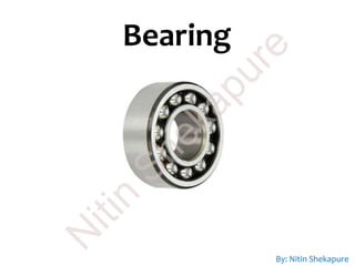
  • 2. Bearing is a machine element that have constrained relative motions and used to reduces friction between moving parts of machine to obtain desired motion or we can say that the machine elements which are support the rotating parts of a machine and reduce friction are called bearings. Due to relative motion between the two parts, there is a friction and wear. In order to reduce the friction and wear also carries away the heat between two parts, a lubricant (like vegetable oil, mineral oil, grease) is provided between the two parts. Bearing The main functions of bearings are: To reduce friction between moving rotatory parts. To support rotating parts of a machine. To bear radial and thrust load. N itin Shekapure
  • 3. Types of bearings According to design, load and shape there are many types of bearings used in industries. The mains bearings can be classified as follows. Friction Bearing •Solid bearings •Split bearings •Self-aligning bush bearings •Adjustable slide bearings Anti-friction bearing •Ball bearings •Single row ball bearings •Double row ball bearing •Self-aligning ball bearings •Angular contact ball bearings •Thrust ball bearings Roller bearings •Self-aligning roller bearings •Tapered roller bearings •Needle roller bearings •Cylindrical roller bearings •Barrel roller bearings •Spherical roller bearings According to Load •Radial or journal bearings •Thrust bearings •Pivot bearings •Slipper bearings According to Shape •Flat shape bearings •Round or cylindrical bearings N itin Shekapure
  • 4. Types of bearings According to the nature of relative motion between the contracting surfaces, the bearings can be classified as follows. Bearings Rolling contact bearing Ball Bearings Roller Bearings Sliding contact or plain or Journal or Sleeve Bearings By: Nitin Shekapure N itin Shekapure
  • 7. Friction bearing As the name implies, in this bearings the bearing surface is in contact with moving surface or the shaft which produces more friction. These bearing are made up of cast iron, bronze, brass and white metal having hollow round shape. Lubricant is used for slow moving and heavy weighted running on shaft. These bearings to support crack shaft, rocker arm of IC engine. Solid bearings It is a simplest hole made in cast iron to support the shaft and form running fit. These are made up of cast iron or bronze in the form of bush and press-fitted in fabricated or cast iron housings. This is used for small and light shafts moving at low speed. A hole is provided on its face of lubrication. N itin Shekapure
  • 8. Split bearings Split bearings are same like solid bearings but have an arrangement of split. Split bearings are made in halves and assembled in special plumber blocks. It has collar on its external surfaces and also made in two parts as shown in figure. Self-aligning bush bearings (Journal Bearing) It consist mainly two parts. The first one is cast iron block and other is bush. These bearing bush are made up of brass or any other soft material in round shape. To protect it from moving, a screw is fixed at one end and this screw is fixed half to the bush and half in block. N itin Shekapure
  • 9. Adjustable slide bearings It can adjust the tightness between bearings and the shaft. This type of bearing has provision for wear adjustment. The bearing is fitted in the tapered hole of the housing for adjustment of wear. The bearing is drawn inside by means of a slotted ring nut. By: Nitin Shekapure N itin Shekapure
  • 10. Advantages and disadvantages of friction bearings: Advantages: • Friction bearings are cheap to produce and have noiseless operation. • They can be easily machined, occupy small radial space and have vibration damping properties. • They can cope with tapped to the foreign matter. Disadvantages: • It damages machines. • It restricts early movement of machine • It produces a lot of heat energy. N itin Shekapure
  • 11. Anti-friction bearing The main purpose of these bearings is to minimize the friction in bearing. Due to this reason, the speed of an object increases and friction and temperature decreases. Such bearing have long life. These bearing also sub-divided into following categories. Single row ball bearings • These bearing have only one groove cut in outer and inner rings with the ball in identical line. • Having high radial load carrying capacity and moderate axial (thrust) load carrying capacity. • Most commonly used type of bearing. Ball bearings A ball bearing is a rolling element bearing that used ball to maintain the separation between the bearing races. The width of these bearing is smaller than the bore diameter or ball. On the basis of load and groove cut, ball bearings are classified in the following types N itin Shekapure
  • 12. Components of Ball bearings N itin Shekapure
  • 13. Races and balls are high carbon chrome steel (to provide resistance to wear) machined and ground to fine limits of 0.0025 mm, highly polished and hardened. N itin Shekapure
  • 14. Double row ball bearings These bearing have two grooves cut in inner and outer rings lie in two rows of the bearing. Self-aligning ball bearings These bearings can withstand with journal loads. These loads are generally inclined due to shaft misalignment. These types of bearings have a spherical bore on the outer race. N itin Shekapure
  • 15. Angular contact ball bearings These bearings are designed to take an axial thrust as well as radial loads. Thrust ball bearings These bearings are useful for taking vertical thrust load but cannot take any radial load. Some special thrust bearings are available which can also take horizontal end thrust. N itin Shekapure
  • 18. Roller bearings Roller bearings are available with the grooved race in the outer and inner members. Roller bearings are capable of carrying the journal (radial) loads. It can work with greater load than ball bearings. To use this bearing, race is required to be locked. On the basis of uses, roller bearings are classified in following types. Needle roller bearingsTapered roller bearingsSelf-aligning roller bearings By: Nitin Shekapure N itin Shekapure
  • 19. Spherical roller bearingsBarrel roller bearingsCylindrical roller bearings By: Nitin Shekapure N itin Shekapure
  • 21. Advantages and disadvantages of anti-friction bearings: Advantages: • Special shielded bearing does not required lubrication again. • It is easy to replace. • It has very long life and has very less friction. • It easy operates on high speed and required less lubrication. Disadvantages: • Initial cost is usually high. • Greater diameter space required for comparable shaft diameter. • Dirt, metal chips and so on, entering the bearings can limit their life causing early failure. • Lesser capacity to withstand shock By: Nitin Shekapure N itin Shekapure
  • 22. MCQ: 64. The function of bearing is a) To locate two machine parts relative to each other. b) To permit the relative motion between two parts. c) To support load. d) All of the above. Explanation : Refer Functions of Bearing N itin Shekapure
  • 23. MCQ: 66. In bearings, due to relative motion, there is a a) Friction and wear b) Corrosion c) Rusting d) All of the above. N itin Shekapure
  • 24. MCQ: 68. The commonly used lubricants in bearings is a) Vegetable oil b) Mineral oil c) Grease d) All of the above. N itin Shekapure
  • 25. MCQ: 67. The function of lubricant is a) To reduce the friction and wear b) To dissipate the heat. c) To increase the strength of the component d) Both a and b N itin Shekapure
  • 26. MCQ: 68. The antifriction bearings means a) Sliding contact bearings, b) Rolling Contact bearings. c) Bush bearings. d) Journal bearings. N itin Shekapure
  • 27. MCQ: 69. The following bearing is not an antifriction bearing a) Single-row deep-groove ball bearing b) Journal bearing c) Cylindrical roller bearing d) Both (b) and (c) Explanation : The rolling contact bearings are also called antifriction bearings. Single-row deep-groove ball bearing and cylindrical roller bearing are rolling contact or antifriction bearings. The journal bearing is sliding contact bearing. N itin Shekapure
  • 28. MCQ: 70. The rolling contact bearings are also known as a) Antifriction bearings b) Friction bearings c) Journal bearings d) None of the above N itin Shekapure
  • 29. MCQ: 71. The rolling contact bearings are also known as a) Antifriction bearings b) Friction bearings c) Journal bearings d) None of the above N itin Shekapure
  • 30. MCQ: 72. The bush bearing is a type of a) Ball bearings b) Journal bearings c) Thrust bearings d) Roller bearings N itin Shekapure
  • 31. MCQ: 73. Rolling contact bearing can take a) Radial and axial force b) Torque c) Bending moment d) Radial force, axial force, torque and bending moment N itin Shekapure
  • 32. MCQ: 74. The rolling contact bearings are classified as: a) Ball bearings and roller bearings b) Single-row bearings and Double-row bearings c) Ball bearings and bush bearings d) Cylindrical bearings and thrust bearings N itin Shekapure
  • 33. MCQ: 75. In ball bearings, the following part is stationary: a) Inner race b) Outer race c) Rolling elements d) None of the above N itin Shekapure
  • 34. MCQ: 76. In ball bearings, generally: a) Inner race is rotating and outer race is stationary b) Both races are stationary c) Inner race is stationary and outer race is rotating d) Both races are rotating N itin Shekapure
  • 35. MCQ: 77. In ball bearings, the relative motion is between: a) Inner race and shaft b) Outer race and frame and casing c) Inner race and outer race d) None of the above N itin Shekapure
  • 36. MCQ: 78. In ball bearings, the relative motion between Inner race and outer race is through a) Balls and rollers b) Bush c) Separator d) Journal N itin Shekapure
  • 37. MCQ: 79. Theis not a part of ball bearings a) Casing b) Outer ring c) Inner ring d) Separator N itin Shekapure
  • 38. MCQ: 80. The following element is not used in rolling contact bearings a) Retainer b) Bush c) Outer race d) All of the above Explanation : The bush is used in sliding contact bearings and not in rolling contact bearings. N itin Shekapure
  • 39. MCQ: 81. In rolling contact bearings, the balls or rollers are inserted between a) Moving and moving elements b) Fixed and moving elements c) Fixed and fixed elements d) None of the above Explanation : In rolling contact bearings, the balls or rollers are inserted between fixed outer race and moving inner race. N itin Shekapure
  • 40. MCQ: 82. In ball bearings, the rolling elements are made of a) Brass b) Cast iron c) Hardened steel d) copper N itin Shekapure
  • 41. MCQ: 83. In ball bearings, the contact between bearings surfaces is a) Rolling contact b) Sliding contact c) Linear contact d) All of the above Explanation : Ball bearing is a type of rolling contact bearing. N itin Shekapure
  • 42. MCQ: 84. In ball bearing _______ is mounted on the shaft a) Outer race b) Inner race c) Separator d) Retainer Imp :Separator and Retainer and cage are same N itin Shekapure
  • 43. MCQ: 85. In ball bearings, the function of separator is a) To separate the balls and rollers. b) To separate inner race and outer race. c) To separate the rolling elements and space them evenly. d) To separate the lubricating oil from the shaft Explanation : All bearings require lubrication N itin Shekapure
  • 44. MCQ: 86. The nature of contact in ball bearing is a) Line contact b) Surface contact c) Point contact d) Volume contact N itin Shekapure
  • 45. MCQ: 87. In ball bearings, the outer race is is a) Supported in casing b) Mounted on shaft c) Supported by bearing d) Supported by key N itin Shekapure
  • 46. MCQ: 88. In rolling contact bearings, the shape of rolling elements is a) Spherical b) Cylindrical c) Tapered cylindrical d) All of the above Explanation : In rolling contact bearings, the rolling elements used are spherical rollers, cylindrical rollers or taper rollers. N itin Shekapure
  • 47. MCQ: 89. The nature of contact in roller bearing a) Line contact b) Surface contact c) Point contact d) Area contact N itin Shekapure
  • 48. MCQ: 90. The needle roller bearing is a special type of a) Cylindrical roller bearing b) Taper roller bearing c) Spherical roller bearing d) None of the above N itin Shekapure
  • 50. A clutch is a mechanical device that engages and disengages the power transmission, especially from driving shaft to driven shaft. Clutch In automobile, a gear box is required to change the speed and torque of the vehicle. If we change a gear, when the engine is engaged with gear box or when the gears are in running position then it can cause of wear and tear of gears. To overcome this problem a device is used between gear box and engine, known as clutch. Clutch is the first element of power train. The main function of clutch is to engage and disengage the engine to transmission, when the driver need or during shifting of gear. When the clutch is in engage position, the power flows from the engine to the wheel and when it is in disengage position, the power is not transmitted. N itin Shekapure
  • 51. Principle of clutch The clutch is based on the friction. When two friction surfaces are brought into contact and pressed, then they are united due to friction force between them. This is the basic principle of clutch. The friction between these two surfaces depends on the area of surface, pressure applied upon them and the friction material between them. The driving member of a clutch is the flywheel mounted on the engine crankshaft and the driven member is pressure plate mounted on the transmission shaft. Some friction plates, sometimes known as clutch plates are kept between these two members. This whole assembly is known as the clutch. N itin Shekapure
  • 52. Friction: Is the resistance to movement exerted by two objects in contact with each other. There are two basic types of friction, Static and Sliding or Kinetic friction. Static Friction: Is the resistance to motion between two stationary objects. Sliding Friction: Is the resistance between a moving object and a stationary object. Coefficient of Friction: The amount of friction between two surfaces is expressed as the coefficient of friction (COF). It is important to note that the coefficient of friction changes for different materials and the state of those materials, smooth, rough etc. Factors that affect friction are: a) The pressure exerted on the surface. b) The coefficient of friction between the materials in contact. c) The surface contact area of the objects. Changing any of these three factors will change the actual friction between the materials in contact. N itin Shekapure
  • 53. Function of clutch: An automobile clutch has following function: 1. It can be disengaged. This allows engine cranking and permits the engine to run without delivering power to the transmission. 2. While disengaging it permits the driver to shift the transmission into various gear according to operating condition. 3. While engaging, the clutch slips momentarily. this provides smooth engagement and lessens the shock on gears, shaft and other parts of automobile. 4. While engaging, the clutch transmits the power to the wheel without slipping, in idea condition. N itin Shekapure
  • 54. Location of clutch in Automobile N itin Shekapure
  • 55. Clutches Positive Clutch Gear Tooth Spiral Friction Clutch Plate or Disc Single Plate Multiple Plate Cone Centrifugal Types (Classification) of Clutch N itin Shekapure
  • 56. Positive Clutch (Dog clutch) The positive clutches are used when positive (no slip) drives are required. These clutches transmit power from the drive shaft to the driven shaft by the interlocking of jaws or teeth. They are rarely used as compared to friction clutch. E.g. jaw clutch, claw clutch, toothed clutch. N itin Shekapure
  • 57. Square jaw clutch; that is the simplest form of a positive clutch. Jaw clutch consists of two halves; one of them permanently fastened to the driver shaft. The other half is movable and is attached to the driven shaft. It can freely slide axially on the shaft, but cannot turn due to feather key. They can transmit power in both directions; they are used when it is not necessary to engage or disengage under load. N itin Shekapure
  • 58. Spiral jaw clutches are used when it needs to transmit power only in one direction; it may be left handed or right handed. They are used when engaging and disengaging while in motion is necessary. N itin Shekapure
  • 59. Application of positive clutch They have very limited use. However, they have some application where the synchronous drive is required. Advantages and disadvantages of positive clutch Advantages • They do not slip. • They can transmit large torque. • Develop no heat during engagement and disengagement because of rigid interlocking (no friction). Disadvantages • Engagement of clutch cannot be possible at high speed. • While starting some relative motion may be required to engage. Extra: What are positive drives? The positive drive means there is no slip, i.e. the input and output have the same speeds under any conditions. N itin Shekapure
  • 60. Friction Clutch They are the most frequently used type of clutch. A friction clutch transmits power by virtue of friction developed between contacting surface. The friction surface is typically flat and perpendicular to the axis of rotation. Two or more surface is pressed together by using compression spring. The friction force is used to bring the driven shaft to the proper speed gradually without excessive slipping. The major types of friction clutches are plate clutch, cone clutch, centrifugal clutch. Various materials have been used for the disc-friction facings, including asbestos in the past. Modern clutches typically use compound organic resin with copper wire facing or a ceramic material. N itin Shekapure
  • 61. Friction Clutch : It may be 1. Single plate clutch 2. Multi-plate clutch 3. Cone clutch. Multi-plate clutch can be either wet or dry. A wet clutch is operated in an oil batch whereas a dry clutch does not use oil. Centrifugal clutch. Semi-centrifugal clutch. Hydraulic clutch. Positive clutch. Vacuum clutch. Electromagnetic clutch. N itin Shekapure
  • 62. Single Plate Clutch • A single plate clutch is commonly used in cars and light vehicles. It has only one clutch plate which is mounted on the splines of the clutch shaft. • A flywheel is mounted on the crankshaft of the engine. • A pressure plate (Driving plate) is connected to the flywheel through the bolts and clutch springs. It is free to slide on the clutch shaft with the movement of clutch pedal. • When clutch is in engaged position, the clutch plate (friction plate) remains gripped between flywheel and pressure plate. Friction linings are provided on both the sides of clutch plate. On one side clutch plate is in touch with flywheel and on other side with pressure plate. • Due to friction on both sides, the clutch plate revolves with engine flywheel. Therefore, clutch transmits engine power to clutch shaft. Clutch shaft is connected to transmission (or gear box) of automobile. Thus, clutch transmits power from engine to transmission system which inturn rotates wheels of engine. N itin Shekapure
  • 63. When the clutch plate is to be disengaged, the clutch pedal is pressed. Because of this pressure plate moves back and clutch plate is disengaged from flywheel. Thus, clutch shaft stops rotating even if engine flywheel is rotating. In this position, power does not reach the wheels and vehicle also stops running. Single plate clutch is shown in Figure: N itin Shekapure
  • 64. Multiplate Clutch Multi-plate clutch consists of more than one clutch plates. Friction surfaces are made in case of multi-plate clutch. Due to increased number of friction surfaces, a multi-plate clutch can transmit large torque. Therefore, it is used in racing cars and heavy motor vehicles witch have high engine power. The clutch plates are alternatively fitted with engine shaft and the shaft of gear box. plates are firmly held by the force of coil springs and they assembled in a drum. One plate slides in the grooves on the flywheel and the next plate slides on spines provided on pressure plate. Thus, each alternate plate slides in grooves on the flywheel and the other on splines of pressure plate. If we take two consecutive plates, then one has inner and other has outer splines. N itin Shekapure
  • 65. When the clutch pedal is pressed, the pressure plate moves back against the force of coil spring, hen the clutch plates are disengaged and engine flywheel and gear box are decoupled. However, when clutch pedal is not pressed the clutch remain in engaged position and the power can be transmitted from engine flywheel to the gear box. This type of clutch has been shown in Figure below: N itin Shekapure
  • 66. Cone Clutch The engine shaft consists of a female cone, the male cone can slide on the clutch shaft. When the clutch is engaged the friction surfaces of the male cone are in contact with that of the female cone due to the force of spring. When the clutch pedal is pressed, the male cone slides against the spring force and the clutch is disengaged. The only advantage of the cone clutch is that the normal force acting on the friction surfaces is greater that the axial force, as compared to the single plate clutch in which the normal force acting on the friction surfaces is equal to the axial force. N itin Shekapure
  • 67. Advantages of friction clutch • Smooth engagement and minimum shock during the engagement. • Friction clutch can be engaged and disengaged when the machine is running since they have no jaw or teeth. • Easy to operate. • They are capable of transmitting partial power. • Friction clutch can act as a safety device. They slip when the torque exceeds a safe value, thus safeguards the machine. • Frequent engagement and disengagement is possible. N itin Shekapure
  • 68. MCQ: 91. _______is the mechanical device used to connect or disconnect the driving shaft from driven shaft at the all of the operator a) Coupling b) Clutch c) Bearing d) Brake N itin Shekapure
  • 69. MCQ: 92. If the two shafts rotating at different speeds are connected by a device, at the will of the operator, to bring them to the same speed, it is called as a) Coupling b) Clutch c) Bearing d) Governer N itin Shekapure
  • 70. MCQ: 93. In automobile, clutch is located a) Inside gear box b) Between gear box and propeller shaft c) Between engine and gear box d) Between propeller shaft and differential N itin Shekapure
  • 71. MCQ: 94. The ________is capable of transmitting a partial power from input shaft to output shaft. a) Flange coupling b) Bushed-pin type coupling c) Clutch d) None of the above N itin Shekapure
  • 72. MCQ: 95. In clutch,___________is a desirable property a) Wear b) Friction c) Surface finish d) Hardness N itin Shekapure
  • 73. MCQ: 95. In clutch, ___________ is a desirable property a) Wear b) Friction c) Surface finish d) Hardness N itin Shekapure
  • 74. MCQ: 96. In friction clutch, increase in coefficient of friction a) Reduces the efficiency b) Reduces the power transmitting capacity c) Increases the power transmitting capacity d) Both a and b N itin Shekapure
  • 75. MCQ: 97. The clutches are used in automobiles a) Line clutch b) Cone clutch c) Centrifugal clutch d) Jaw clutch N itin Shekapure
  • 76. MCQ: 98. _______ are most commonly used types of clutches in automobile. a) Cone clutch and centrifugal clutch b) Single plate clutch and multiple clutch c) Cone clutch d) Multiplate clutch and centrifugal clutch N itin Shekapure
  • 77. MCQ: 99. _______ is a type of frictional clutch a) Plate clutch b) Centrifugal clutch c) Cone clutch d) All of the above N itin Shekapure
  • 78. MCQ: 100.In single plate clutch a) The pressure plate is on driving shaft and friction plate is on driven shaft b) The friction plate is on driving shaft and pressure plate is on driven shaft c) The friction plate is on driving as well as driven shaft d) None of the above N itin Shekapure
  • 79. MCQ: 101. In single plate clutch a) The pressure plate is on driving shaft and friction plate is on driven shaft b) The friction plate is on driving shaft and pressure plate is on driven shaft c) The friction plate is on driving as well as driven shaft d) None of the above N itin Shekapure
  • 80. MCQ: 102. Which of the following statement is incorrect ? a) Clutch is normally in engaged condition b) Friction clutch is positive type c) Springs are used in clutch d) Single plate clutch is dry type N itin Shekapure
  • 81. MCQ: 103. Springs are used in a) Plate clutches b) Cone clutches c) Centrifugal clutches d) All of the above Explanation : In all friction clutches, helical compression springs are used to exert axial force between driving and driven plates. N itin Shekapure
  • 82. MCQ: 104.In friction clutches, the friction plate is also known as a) Pressure Plate b) Clutch plate c) Driving plate d) All of the above N itin Shekapure
  • 83. MCQ: 105. In friction clutch, asbestos is used as a) Insulating material b) Lubricating material c) Protective material d) Friction material N itin Shekapure
  • 84. MCQ: 106.Single plate clutch is normally a) Dry type b) Wet type c) Grease lubricated d) Oil lubricated N itin Shekapure
  • 85. MCQ: 107. In disengaged condition of clutch a) Driving shaft as well as driven shaft are stationary. b) Driving shaft as well as driven shaft are rotating c) Driving shaft is rotating while driven shaft is stationary. d) Driving shaft is stationary while driven shaft is rotating. N itin Shekapure
  • 86. MCQ: 108.In clutch, during engagement, the axial force between driving and driven plates is created by a) Clutch padal b) Clutch cable c) Splined shaft d) Helical compression spring N itin Shekapure
  • 87. MCQ: 109.The overall size of ______clutch is large a) Cone b) Centrifugal c) Single plate d) All of the above N itin Shekapure
  • 88. MCQ: 110. Which of the following statement is correct ? a) Single plate clutch is wet type while multi-plate clutch is dry type. b) Single plate clutch is dry type while multi-plate clutch is wet. c) Single plate clutch as well as multi-plate clutch are wet type d) Single plate clutch as well as multi-plate clutch are dry type N itin Shekapure
  • 90. A clutch is a mechanical device that engages and disengages the power transmission, especially from driving shaft to driven shaft. Brake In automobile, a gear box is required to change the speed and torque of the vehicle. If we change a gear, when the engine is engaged with gear box or when the gears are in running position then it can cause of wear and tear of gears. To overcome this problem a device is used between gear box and engine, known as clutch. Clutch is the first element of power train. The main function of clutch is to engage and disengage the engine to transmission, when the driver need or during shifting of gear. When the clutch is in engage position, the power flows from the engine to the wheel and when it is in disengage position, the power is not transmitted. By: Nitin Shekapure N itin Shekapure
  • 91. Functions of vehicle braking There are two main functions of brakes : 1. To slow down or stop the vehicle in the shortest possible time at the time of need. 2. To control the speed of vehicle at turns and also at the time of driving down on a hill slope. By: Nitin Shekapure N itin Shekapure
  • 92. Principle of vehicle braking Braking of a vehicle depends upon the static function that acts between tyres and road surface. Brakes work on the following principle to stop the vehicle : “The kinetic energy due to motion of the vehicle is dissipated in the form of heat energy due to friction between moving parts (wheel or wheel drum) and stationary parts of vehicle (brake shoes)”. The heat energy so generated due to application of brakes is dissipated into air. Brakes operate most effectively when they are applied in a manner so that wheels do not lock completely but continue to roll without slipping on the surface of road. N itin Shekapure
  • 93. Classification of brakes On the Basis of Method of Actuation  Foot brake (also called service brake) operated by foot pedal.  Hand brake – it is also called parking brake operated by hand. On the Basis of Mode of Operation  Mechanical brakes (Drum Brake & Disk (Disc) Brake)  Hydraulic brakes  Air brakes  Vacuum brakes  Electric brakes. By: Nitin Shekapure N itin Shekapure
  • 94. On the Basis of Action on Front or Rear Wheels  Front-wheel brakes  Rear-wheel brakes. On the Basis of Method of Application of Braking Contact  Internally – expanding brakes  Externally – contracting brakes. By: Nitin Shekapure N itin Shekapure
  • 95. Disk brake (Caliper disk beake) In a disc brake, the fluid from the master cylinder is forced into a caliper where it presses against a piston. The piston in turn squeezes two brake pads against the disc (rotor), which is attached to wheel, forcing it to slow down or stop. Disc Brake and Brake of a Bicycle Similar to a bicycle brake where two rubber pads run against the wheel rim creating friction. But in a disc brake, the brake pads squeeze the rotor instead of the wheel, and the force is transmitted hydraulically instead of through a cable. N itin Shekapure
  • 96. Drum brake (Internal expanding shoe brake) The drum brake has a metal brake drum that encloses the brake assembly at each wheel. Two curved brake shoes expand outward to slow or stop the drum which rotates with the wheel. Working: • Drum brakes work on the same principle as the disc brakes. • Shoes press against a rotating surface. • In this system that surface is called a drum. • Drum brake also has an adjuster mechanism, an emergency brake mechanism and lots of springs. • The shoes are pulled away from the drum by the springs when the brakes are released. N itin Shekapure
  • 97. Some more Points • Most modern cars have disc brakes on front wheels and drum brakes on rear wheels and some wheels have disc brakes on all four wheels. • To increase safety, most modern car brake systems are broken into two circuits, with two wheels on each circuit. • If a fluid leak occurs in one circuit, only two of the wheels will loose their brakes and the car will still be able to stop when we press the break pedal Application • Drum brake: Used in automobile vehicles ( trucks, buses, cars, motorcycles, scooter, etc. • Disk brake: Used in modern motorcycles and racing cars due to its excellent control . Also used in conveyers N itin Shekapure
  • 98. Short notes on miscellaneous Braking systems Air Brakes Air brakes are applied by the pressure of compressed air. Air pressure applies force on brakes shoes through suitable linkages to operate brakes. An air compressor is used to compress air. This compressor is run by engine power. Vacuum Brakes Vacuum brakes are a piston or a diaphragm operating in a cylinder. For application of brakes one side of piston is subjected to atmospheric pressure while the other is applied vacuum by exhausting air from this side. A force acts on the piston due to difference of pressure. This force is used to operate brake through suitable linkages. Electric Brakes In electrical brakes an electromagnet is used to actuate a cam to expand the brake shoes. The electromagnet is energized by the current flowing from the battery. When flow of current is stopped the cam and brake shoes return to their original position and brakes are disengaged. Electric brakes are not used in automobiles as service brakes. N itin Shekapure
  • 99. MCQ: 111. The following mechanical element is meant for absorbing the kinetic or potential energy of a moving system and converts it into heat which is finally dissipated to the surrounding: a) Clutch b) Brake c) Spring d) Flywheel N itin Shekapure
  • 100. MCQ: 112. _________ brake is not used in vehicles. a) Band b) Disk c) Internal expanding shoe d) Both a and b N itin Shekapure
  • 101. MCQ: 113. Disk brake is also known as a) Drum disk brake b) Caliper disk brake c) Internal disk brake d) Shoe disk brake N itin Shekapure
  • 102. MCQ: 114. Now a days ______ brakes are used in motor cycle a) Drum brake b) Disk brake c) Pads d) None of the above N itin Shekapure
  • 103. MCQ: 115. Racing cars used a) Drum brakes b) Disk brakes c) Band brakes d) Band and block brakes N itin Shekapure
  • 104. MCQ: 116. Disk brakes are used in motor cycles due to a) High torque transmission capacity b) High power transmission capacity c) High mechanical efficiency d) Excellent control N itin Shekapure
  • 105. MCQ: 117. Disk brakes consists of a) Shoes b) Blocks c) Pads d) None of the above N itin Shekapure
  • 106. MCQ: 118. The energy absorb by the brake is a) Strain energy b) Kinetic energy c) Potential energy d) b or c N itin Shekapure
  • 107. MCQ: 119. The energy absorb by the brake is dissipated in the from of_____ a) Heat b) Kinetic energy c) Potential energy d) All of the above N itin Shekapure
  • 108. MCQ: 120. The following mechanical element absorb the power a) Clutch b) Spring c) Flywheel d) Brake N itin Shekapure
  • 109. Power Transmission devices By: Nitin Shekapure N itin Shekapure
  • 110. Power Transmission devices or drives • Chain drives • Gear drives • The system that is used to transmit power from one mechanical element to another mechanical element. • The power transmission and speed reduction between prime mover (Electric motor, IC engines, Gas turbine, Steam turbines, etc.) and the driven machine can be achieved by using various transmitting systems. • In order to achieve a high power to weight ratio, the prime movers are designed with high operating speeds which are usually higher than required by the driven machines. Types of transmitting system • Belt drives • Rope drives By: Nitin Shekapure N itin Shekapure
  • 111. Factors to select transmission system • Distance between driver and driven pulley shaft. • Operational speed. • Power to be transmitted By: Nitin Shekapure N itin Shekapure
  • 112. Belt Drives By: Nitin Shekapure N itin Shekapure
  • 113. Belt Drives • Power is to be transmitted between the parallel shaft. • Consists of two pulleys over which a endless belt is passed encircling (enclosing) the both. • Rotary motion is transmitted from driving pulley to driven pulley. • As the power is transmitted because of the friction between the belt and pulley surface, it is not a positive drive and there can be a small percentage of slip. N itin Shekapure
  • 114. Belt drive is an example of flexible machine element used to transmit power from one shaft to another. Belts are the cheapest mode of power transmission. The selection of a belt drive depends upon; • The direction of belt motion. • Power to be transmitted. • The velocity of shaft and Velocity ratio. • Speed reduction ratio • The distance between shafts, space available. • Service conditions. • Space available • Shaft layout Belt Drives By: Nitin Shekapure N itin Shekapure
  • 115. If a huge amount of power is to be transmitted, then a single belt may not be sufficient. In such a case, wide pulleys (for V-belts or circular belts) with a number of grooves are used. Then a belt in each groove is provided to transmit the required amount of power from one pulley to another. Material used for Belts • Leather belts • Cotton or fabric belts • Rubber belt • Balata belts By: Nitin Shekapure N itin Shekapure
  • 116. Types of Belt Drives The belt drives are usually classified into the following three groups : 1. Light drives: These are used to transmit small powers at belt speeds upto about 10 m/s, as in agricultural machines and small machine tools. 2. Medium drives: These are used to transmit medium power at belt speeds over 10 m/s but up to 22 m/s, as in machine tools. 3. Heavy drives: These are used to transmit large powers at belt speeds above 22 m/s, as in compressors and generators. By: Nitin Shekapure N itin Shekapure
  • 117. Types of Belt Though there are many types of belts used these days, yet the following are important from the subject point of view By: Nitin Shekapure N itin Shekapure
  • 118. Flat Belt Flat belt is mostly used in the factories and workshops, where a moderate amount of power is to be transmitted, from one pulley to another when the two pulleys are not more than 8 meters apart. V Belt The V-belt is mostly used in the factories and workshops, where a moderate amount of power is to be transmitted, from one pulley to another, when the two pulleys are very near to each other. The circular belt or rope is mostly used in the factories and workshops, where a great amount of power is to be transmitted, from one pulley to another, when the two pulleys are more than 8 meters apart. Circular Belt N itin Shekapure
  • 119. Types of Flat Belt Drive 1. Open belt drive 2. Crossed or twist belt drive 3. Quarter turn belt drive 4. Belt drive with idler pulleys 5. Compound belt drive 6. Stepped or cone pulley drive 7. Fast and loose pulley drive By: Nitin Shekapure N itin Shekapure
  • 120. 1. Open belt drive The open belt drive, is used with shafts arranged parallel and rotating in the same direction. N itin Shekapure
  • 121. 2. Crossed or twist belt drive The crossed or twist belt drive, is used with shafts arranged parallel and rotating in the opposite directions. N itin Shekapure
  • 122. 3. Quarter turn belt drive The quarter turn belt drive also known as right angle belt drive is used with shafts arranged at right angles and rotating in one definite direction. Quarter turn belt drive Quarter turn belt drive with guided pulley N itin Shekapure
  • 123. 4. Belt drive with idler pulleys A belt drive with an idler pulley is used with shafts arranged parallel and when an open belt drive cannot be used due to small angle of contact on the smaller pulley. N itin Shekapure
  • 124. 5. Compound belt drive A compound belt drive is used when power is transmitted from one shaft to another through a number of pulleys. N itin Shekapure
  • 125. 6. Stepped or cone pulley drive A stepped or cone pulley drive is used for changing the speed of the driven shaft while the main or driving shaft runs at constant speed. This is accomplished by shifting the belt from one part of the steps to the other.N itin Shekapure
  • 126. 7. Fast and loose pulley drive A fast and loose pulley drive is used when the driven or machine shaft is to be started or stopped when ever desired without interfering with the driving shaft. A pulley which is keyed to the machine shaft is called fast pulley and runs at the same speed as that of machine shaft. A loose pulley runs freely over the machine shaft and is incapable of transmitting any power. When the driven shaft is required to be stopped, the belt is pushed on to the loose pulley by means of sliding bar having belt forks. N itin Shekapure
  • 127. V Belts • The V-belts are made of fabric and cords moulded in rubber and covered with fabric and rubber. • These belts are moulded to a trapezoidal shape and are made endless. • These are suitable for short drives i.e. when the shafts are at a short distance apart. • The included angle for the V-belt is usually from 30° – 40°. In case of flat belt drive, the belt runs over the pulleys whereas in case of V-belt drive, the rim of the pulley is grooved in which the V-belt runs. • The effect of the groove is to increase the frictional grip of the V-belt on the pulley and thus to reduce the tendency of slipping. • In order to have a good grip on the pulley, the V-belt is in contact with the side faces of the groove and not at the bottom. • The power is transmitted by the wedging action between the belt and the V-groove in the pulley. N itin Shekapure
  • 128. V Belts Cross-section of a V-belt Cross-section of a V-grooved pulley N itin Shekapure
  • 129. Advantages and Disadvantages of V-belt Drive Over Flat Belt Drive Advantages 1. The V-belt drive gives compactness due to the small distance between the centres of pulleys. 2. The drive is positive, because the slip between the belt and the pulley groove is negligible. 3. Since the V-belts are made endless and there is no joint trouble, therefore the drive is smooth. 4. It provides longer life, 3 to 5 years. 5. It can be easily installed and removed. 6. The operation of the belt and pulley is quiet. 7. The belts have the ability to cushion the shock when machines are started. 8. The high velocity ratio be obtained 9. The V-belt may be operated in either direction with tight side of the belt at the top or bottom. N itin Shekapure
  • 130. Advantages and Disadvantages of V-belt Drive Over Flat Belt Drive Disadvantages 1. The V-belt drive cannot be used with large centre distances. 2. The V-belts are not so durable as flat belts. 3. The construction of pulleys for V-belts is more complicated than pulleys for flat belts. 4. Since the V-belts are subjected to certain amount of creep, therefore these are not suitable for constant speed application such as synchronous machines, and timing devices. 5. The belt life is greatly influenced with temperature changes, improper belt tension and mismatching of belt lengths. 6. The centrifugal tension prevents the use of V-belts at speeds below 5 m/s and above 50m/s. N itin Shekapure
  • 131. Velocity Ratio (Speed Ratio) of Belt Drive It is the ratio between the velocities of the driver and the follower or driven. It may be expressed, mathematically, as discussed below : Let d1 = Diameter of the driver, d2 = Diameter of the follower, N1 = Speed of the driver in r.p.m., and N2 = Speed of the follower in r.p.m. Length of the belt that passes over the driver, in one minute = Π d1 N1 Similarly, length of the belt that passes over the follower, in one minute = Π d2 N2 Since the length of belt that passes over the driver in one minute is equal to the length of belt that passes over the follower in one minute, therefore Π d1 N1 = Π d2 N2 N itin Shekapure
  • 132. Velocity Ratio (Speed Ratio) of Belt Drive When the thickness of the belt (t) is considered, then velocity ratio, The velocity ratio of a belt drive may also be obtained as discussed below : We know that peripheral velocity of the belt on the driving pulley, and peripheral velocity of the belt on the driven or follower pulley, N itin Shekapure
  • 133. Velocity Ratio of a Compound Belt Drive Sometimes the power is transmitted from one shaft to another, through a number of pulleys. Consider a pulley 1 driving the pulley 2. Since the pulleys 2 and 3 are keyed to the same shaft, therefore the pulley 1 also drives the pulley 3 which, in turn, drives the pulley 4.N itin Shekapure
  • 135. Rope Drive • The rope drives are widely used where a large amount of power is to be transmitted, from one pulley to another, over a considerable distance. • It may be noted that the use of flat belts is limited for the transmission of moderate power from one pulley to another when the two pulleys are not more than 8 meters apart. If large amounts of power are to be transmitted by the flat belt, then it would result in excessive belt cross-section. • It may be noted that frictional grip in case of rope drives is more than that in V-drive. • One of the main advantage of rope drives is that a number of separate drives may be taken from the one driving pulley. • For example, in many spinning mills, the line shaft on each floor is driven by ropes passing directly from the main engine pulley on the ground floor. N itin Shekapure
  • 136. Rope Drive The rope drives use the following two types of ropes : 1. Fiber ropes, and 2. Wire ropes. The fiber ropes operate successfully when the pulleys are about 60 meters apart, while the wire ropes are used when the pulleys are up to 150 meters apart. N itin Shekapure
  • 137. Chain Drives By: Nitin Shekapure N itin Shekapure
  • 138. Chain Drive • We have seen in belt and rope drives that slipping may occur. • In order to avoid slipping, steel chains are used. • The chains are made up of rigid links which are hinged together in order to provide the necessary flexibility for warping around the driving and driven wheels. • The wheels have projecting teeth and fit into the corresponding recesses, in the links of the chain. • The wheels and the chain are thus constrained to move together without slipping and ensures perfect velocity ratio. The toothed wheels are known as sprocket wheels or simply sprockets. These wheels resemble to spur gears. N itin Shekapure
  • 139. Chain Drive The chains are mostly used to transmit motion and power from one shaft to another, when the distance between the centres of the shafts is short such as in bicycles, motor cycles, agricultural machinery, road rollers, etc. By: Nitin Shekapure N itin Shekapure
  • 140. Types of power transmission Chain Of the several types of chains, following two types are mainly use for power transmission 1. Roller chains 2. Silent or Inverted tooth chains By: Nitin Shekapure N itin Shekapure
  • 141. Advantages Advantages and Disadvantages of Chain Drive Over Belt or Rope Drive 1. As no slip takes place during chain drive, hence perfect velocity ratio is obtained. 2. Since the chains are made of metal, therefore they occupy less space in width than a belt or rope drive. 3. The chain drives may be used when the distance between the shafts is less. 4. The chain drive gives a high transmission efficiency (upto 98 per cent). 5. The chain drive gives less load on the shafts. 6. The chain drive has the ability of transmitting motion to several shafts by one chain only. N itin Shekapure
  • 142. Disadvantages Advantages and Disadvantages of Chain Drive Over Belt or Rope Drive 1. The production cost of chains is relatively high. 2. The chain drive needs accurate mounting and careful maintenance. 3. The chain drive has velocity fluctuations especially when unduly stretched N itin Shekapure
  • 144. Gear A gear is a wheel with teeth that mesh together with other gears. Gears change the • Speed • Torque (rotational force) • Direction of rotating axles. By: Nitin Shekapure N itin Shekapure
  • 145. History of Gear Indian history as per our mythological stories is more than 12,000 years old. Since then people living here have been striving to improve the living conditions. We also know that earlier people were living in the caves and the doors of the caves were made of granite. How were these heavy doors opened and closed? They were opened and closed by none other than a system with gear mechanism, wheel, lever and rope drives. However, the documented evidence has been lost due to destruction by the invaders and improper storing of palm leaf literature. The guru Kula method of teaching and passing of the information from mouth to ear procedure and keeping some of the advances as closely guarded secret have resulted in poor dissemination of the knowledge and documentation. But, the knowledge of gears has gone from India to east through some of the globe trotters from China as back as 2600 years BC. They have used the gears then ingeniously in chariots for measuring the speed and other mechanisms. Primitive gears shown in figure on next slide were first used in door drive mechanism in temples and caves, and water lifting mechanisms 2600 B.C. in India and elsewhere. N itin Shekapure
  • 146. Aristotle in the fourth century B.C. mentions in his writings that gears were being used very commonly in many applications. Classical origin of worm gearing was made by Archimedes 287-212 B.C. Vitruvius a military engineer in his writing in 28 B.C. has described a number of gear applications Primitive gears made of wood Water wheel and grain mill described by Vitruvius 40 B.C N itin Shekapure
  • 147. Gear - Purpose Sports cars go fast (have speed) but cannot pull any weight. Big trucks can pull heavy loads (have power), but cannot go fast. Gears increase or decrease the power or speed. By: Nitin Shekapure N itin Shekapure
  • 148. Gears are toothed members which transmit power / motion between two shafts by meshing without any slip. Hence, gear drives are also called positive drives. In any pair of gears, the smaller one is called pinion and the larger one is called gear immaterial of which is driving the other. When pinion is the driver, it results in step down drive in which the output speed decreases and the torque increases. On the other hand, when the gear is the driver, it results in step up drive in which the output speed increases and the torque decreases. The profile of gear tooth is either involute or cycloid Gears N itin Shekapure
  • 149. Gears are most commonly used for power transmission They can be applied between two shafts which are • Parallel • Collinear • Perpendicular and intersecting • Perpendicular and nonintersecting • Inclined at any arbitrary angle Gears N itin Shekapure
  • 150. Classification of Gears Gears are classified according to the shape of the tooth pair and disposition into • Spur • Helical • Double helical • Straight bevel • Spiral bevel • Worm and spiral gears By: Nitin Shekapure N itin Shekapure
  • 151. Spur Gears • Spur gears have their teeth parallel to the axis. • They are used for transmitting power between two parallel shafts. • They are simple in construction, easy to manufacture and cost less. • They have highest efficiency and excellent precision rating. • They are used in high speed and high load application in all types of trains and a wide range of velocity ratios. • Hence, they find wide applications right from clocks, household gadgets, motor cycles, automobiles, and railways to aircrafts. • Spur gear pair can be used for reduction ratio up to 6:1 • The efficiency of spur gear is high (96 % to 99 %) N itin Shekapure
  • 152. Helical Gears • Helical gears are used for parallel shaft drives. • They have teeth inclined to the axis as shown in Figure • Hence for the same width, their teeth are longer than spur gears and have higher load carrying capacity. • Their contact ratio is higher than spur gears and they operate smoother and quieter than spur gears. • Their precision rating is good. • They are recommended for very high speeds and loads. • Thus, these gears find wide applications in automotive gearboxes. • Their efficiency is slightly lower than spur gears. • The helix angle also introduces axial thrust on the shaft. N itin Shekapure
  • 154. Double Helical Gear or Herringbone Gear • Double helical or Herringbone gears used for transmitting power between two parallel shafts. • They have opposing helical teeth with or without a gap depending on the manufacturing method adopted. • Two axial thrusts oppose each other and nullify. • Hence the shaft is free from any axial force. • Though their load capacity is very high. • Manufacturing difficulty makes them costlier than single helical gear. • Their applications are limited to high capacity reduction drives like that of cement mills and crushers. N itin Shekapure
  • 155. Double Helical Gear or Herringbone Gear By: Nitin Shekapure N itin Shekapure
  • 156. Internal Gear • Internal gears are used for transmitting power between two parallel shafts. • In these gears, annular wheels are having teeth on the inner periphery. • This makes the drive very compact • In these drives, the meshing pinion and annular gear are running in the same direction Their precision rating is fair. • They are useful for high load and high speed application with high reduction ratio. • Applications of these gears can be seen in planetary gear drives of automobile automatic transmissions, reduction gearboxes of cement mills, step-up drives of wind mills. • They are not recommended for precision meshes because of design, fabrication, and inspection limitations. N itin Shekapure
  • 157. Internal Gear Diwabus transmission (Voith) with internal gear N itin Shekapure
  • 158. Rack and Pinion • Rack is a segment of a gear of infinite diameter. • The tooth can be spur as in Fig. 1 or helical as in Fig 2 • This type of gearing is used for converting rotary motion into translatory motion or visa versa. Fig 1 Fig 2 By: Nitin Shekapure N itin Shekapure
  • 159. Typical example of rack and pinion applications are shown below Rack and Pinion Lathe carriage drive mechanism showing rack and pinion arrangement Radial drilling machine spindle movement with rack and pinion arrangement N itin Shekapure
  • 160. Bevel Gear Straight Bevel Gear • Straight bevel gears are used for transmitting power between intersecting shafts. • They can operate under high speeds and high loads. • Their precision rating is fair to good. They are suitable for 1:1 and higher velocity ratios and for right-angle meshes to any other angles. • Their good choice is for right angle drive of particularly low ratios. • Wide application of the straight bevel drives is in automotive differentials, right angle drives of blenders and conveyors. • A typical application of straight bevel used in differential application. N itin Shekapure
  • 161. Bevel Gear Straight Bevel Gear Differential of an Automobile By: Nitin Shekapure N itin Shekapure
  • 162. Bevel Gear Spiral Bevel Gear • Spiral bevel gears are also used for transmitting power between intersecting shafts. • Because of the spiral tooth, the contact length is more and contact ratio is more. • They operate smoother than straight bevel gears and have higher load capacity. • But, their efficiency is slightly lower than straight bevel gear. • Usage of spiral bevel gears in an automobile differential. N itin Shekapure
  • 163. Bevel Gear Spiral Bevel Gear By: Nitin Shekapure N itin Shekapure
  • 164. Bevel Gear Hypoid Bevel Gear • These gears are also used for right angle drive in which the axes do not intersect. • This permits the lowering of the pinion axis which is an added advantage in automobile in avoiding hump inside the automobile drive line power transmission. • However, the non – intersection introduces a considerable amount of sliding and the drive requires good lubrication to reduce the friction and wear. • Their efficiency is lower than other two types of bevel gears. • These gears are widely used in current day automobile drive line power transmission. N itin Shekapure
  • 165. Bevel Gear Hypoid Bevel Gear N itin Shekapure
  • 166. Worm Gear • Worm and worm gear pair consists of a worm, which is very similar to a screw and a worm gear, which is a helical gear. • They are used in right-angle skew shafts. • In these gears, the engagement occurs without any shock. • The sliding action prevalent in the system while resulting in quieter operation produces considerable frictional heat. • High reduction ratios 8 to 400 are possible. • Efficiency of these gears is low anywhere from 90% to 40 %. • Higher speed ratio gears are non-reversible. • Their precision rating is fair to good. • They need good lubrication for heat dissipation and for improving the efficiency. • The drives are very compact. By: Nitin Shekapure N itin Shekapure
  • 167. Worm Gear Worm gearing finds wide application in material handling and transportation machinery, machine tools, automobiles etc. An industrial worm gear box used for converting horizontal to vertical drive By: Nitin Shekapure N itin Shekapure
  • 168. Spiral Gear • Spiral gears are also known as crossed helical gears. • They have high helix angle and transmit power between two non- intersecting non-parallel shafts. • They have initially point contact under the conditions of considerable sliding velocities finally gears will have line contact. • Hence, they are used for light load and low speed application such as instruments, sewing machine etc. • Their precision rating is poor. • An application of spiral gear used in textile machinery. N itin Shekapure
  • 170. Gear Trains Any combination of gears used for transmitting motion and power from one shaft to another shaft is called a gear train. There are basically two types of gear trains • Simple gear train • Compound gear train • Planetary gear train By: Nitin Shekapure N itin Shekapure
  • 171. The simple gear train is used where there is a large distance to be covered between the input shaft and the output shaft. Each gear in a simple gear train is mounted on its own shaft. When examining simple gear trains, it is necessary to decide whether the output gear will turn faster, slower, or the same speed as the input gear. The circumference (distance around the outside edge) of these two gears will determine their relative speeds. Suppose the input gear's circumference is larger than the output gear's circumference. The output gear will turn faster than the input gear. On the other hand, the input gear's circumference could be smaller than the output gear's circumference. In this case the output gear would turn more slowly than the input gear. If the input and output gears are exactly the same size, they will turn at the same speed. In simple gear trains there are several gears between the input gear and the output gear. These middle gears are called idler gears. Idler gears do not affect the speed of the output gear. Simple Gear Trains N itin Shekapure
  • 172. In a compound gear train at least one of the shafts in the train must hold two gears. Compound gear trains are used when large changes in speed or power output are needed and there is only a small space between the input and output shafts. The number of shafts and direction of rotation of the input gear determine the direction of rotation of the output gear in a compound gear train. The train in Figure has two gears in between the input and output gears. These two gears are on one shaft. They rotate in the same direction and act like one gear. There are an odd number of gear shafts in this example. As a result, the input gear and output gear rotate in the same direction. Since two pairs of gears are involved, their ratios are “compounded”, or multiplied together. Compound Gear Trains N itin Shekapure
  • 173. Planetary Gear Trains In this gear system, the yellow gear (the sun) engages all three red gears (the planets) simultaneously. All three are attached to a plate (the planet carrier), and they engage the inside of the blue gear (the ring) instead of the outside. Because there are three red gears instead of one, this gear train is extremely rugged. The output shaft is attached to the blue ring gear, and the planet carrier is held stationary -- this gives the same 6:1 gear ratio. Another interesting thing about planetary gear sets is that they can produce different gear ratios depending on which gear you use as the input, which gear you use as the output, and which one you hold still. For instance, if the input is the sun gear, and we hold the ring gear stationary and attach the output shaft to the planet carrier, we get a different gear ratio. In this case, the planet carrier and planets orbit the sun gear, so instead of the sun gear having to spin six times for the planet carrier to make it around once, it has to spin seven times. This is because the planet carrier circled the sun gear once in the same direction as it was spinning, subtracting one revolution from the sun gear. So in this case, we get a 7:1 reduction. N itin Shekapure
  • 174. Velocity ratio of Gear drive Velocity ratio is defined as the ratio of the speed of the driven shaft to the speed of the driver shaft. One gear is a driver, which has d1, N1, ω1 as diameter, speed and angular speed respectively. Another gear is driven connected to the driven shaft has d2, N2, ω2 as diameter, speed and angular speed respectively. Angular speeds of the two gears will be 11 2 N  12 2 N  The peripheral velocity of the driver and driven shafts for the meshing pair of gear is equal and is given by 2 1 1 d VP  11 Nd 2 2 2 d  22 Nd= = = N itin Shekapure
  • 175. Hence velocity ratio (n) = 2 1 1 2 1 2 d d N N    T1 and T 2 are the number of teeth on driver gear and driven gear, since the pair of gear as the same module (m),then 11 Tmd  22 Tmd ; 2 1 2 1 1 2 T T d d N N n  N itin Shekapure
  • 176. SUMMARY OF GEAR TYPES Type Features and Precision Rating Applications Comments Regarding Precision Spur Parallel Shafting. High speeds and loads highest efficiency Precision Rating is excellent Applicable to all types of trains and a wide range of velocity ratios. Simplest tooth elements offering maximum precision. First choice, recommended for all the gear meshes, except where very high speeds and loads or special features of other types, such as right angle drive, cannot be avoided. Helical Parallel Shafting. Very high speeds and loads. Efficiency slightly less than spur mesh. Precision Rating is good Most applicable to high speeds and loads; also used whenever spurs are used. Equivalent quality to spurs, except for complication of helix angle. Recommended for all high-speed and high- load meshes. Axial thrust component must be accommodated. N itin Shekapure
  • 177. Type Features and Precision Rating Applications Comments Regarding Precision Crossed Helical Skewed shafting. Point contact. High sliding Low speeds Light loads Precision Rating is poor Relatively low velocity ratio; low speeds and light loads only. Any angle skew shafts. To be avoided for precision meshes. Point contact limits capacity and precision. Suitable for right angle drives, if light load. A less expensive substitute for bevel gears. Good lubrication essential because of point of contact and high sliding action. Internal spur Parallel shafts High speeds High loads Precision Rating is fair Internal drives requiring high speeds and high loads; offers low sliding and high stress loading; good for high capacity, long life. Used in planetary gears to produce large reduction ratios. Not recommended for precision meshes because of design, fabrication, and inspection limitations. Should only be used when internal feature is necessary. SUMMARY OF GEAR TYPES N itin Shekapure
  • 178. SUMMARY OF GEAR TYPES Type Features and Precision Rating Applications Comments Regarding Precision Bevel Intersecting shafts, High speeds, High loads. Precision Rating is fair to good Suitable for 1:1 and higher velocity ratios and for right- angle meshes (and other angles) Good choice for right angle drive, particularly low ratios. However complicated both form and fabrication limits achievement of precision. Should be located at one of the less critical meshes of the train. Worm mesh Right-angle skew shafts, High velocity ratio, High speeds and loads, Low efficiency, Most designs nonreversible. Precision rating is fair to good High velocity ratio Angular meshes High loads Worm can be made to high precision, but worm gear has inherent limitations. To be considered for average precision meshes, but can be of high precision with care. Best choice for combination high velocity ratio and right-angle drive. High sliding requires excellent lubrication. N itin Shekapure
  • 179. SUMMARY OF GEAR TYPES Type Features and Precision Rating Applications Comments Regarding Precision Specials - Face, Spiroid, Helicon, Beveloid Intersecting and skew shafts. Modest speeds and loads. Precision Rating is fair to good Special cases To be avoided as precision meshes. Significant non- conjugate action with departure from nominal center distance and shaft angles. Fabrication needs special equipment and inspection is limited. N itin Shekapure
  • 180. MCQ: 121. The prime movers should be ideally designed for a) Weight to power ratio b) High power to weight ratio c) High weight to volume ratio d) None of the above N itin Shekapure
  • 181. MCQ: 122. The example of prime mover is a) Electric motor b) Diesel engine c) Petrol engine d) All of the above Explanation : Device supplying the torque to drive any machine is called prime mover. Electric motor, diesel engine, petrol engine, steam engine, steam turbine, gas turbine, etc. are the examples of prime mover. N itin Shekapure
  • 182. MCQ: 123. Find the odd element out from the following list a) Electric motor b) Centrifugal pump c) Steam turbine d) I. C. engine Explanation : Centrifugal pump is not a prime mover while remaining are prime movers. N itin Shekapure
  • 183. MCQ: 124. The power transmission devices are used for transmitting the power a) Machine to prime mover b) Prime mover to machine c) Prime mover to prime d) All of the above N itin Shekapure
  • 184. MCQ: 125. Following is not an example of power transmission device a) Bearing b) Gear pair c) Belt d) Chain N itin Shekapure
  • 185. MCQ: 126. ________ is an example of power transmission device a) Bearing b) Gear c) Brake d) All of the above N itin Shekapure
  • 186. MCQ: 127. ________ is a mechanism used for transmitting the power and motion from prime mover to the machine a) Bearing b) Drive c) Brake d) None of the above N itin Shekapure
  • 187. MCQ: 128. ________ is an example of drive a) Chain b) Belt c) Gear d) All of the above N itin Shekapure
  • 188. MCQ: 129. ________ is used for transmitting the power between two pulleys a) Chain drive b) Belt drive c) Gear drive d) All of the above N itin Shekapure
  • 189. MCQ: 130. The essential element of belt drive is a) Driving pulley b) Driven pulley c) Belt d) All of the above N itin Shekapure
  • 190. MCQ: 131. In belt drive, power is transmitted from a) Driving pulley to driven pulley b) Driven pulley to driving pulley c) Small pulley to large pulley d) Large pulley to small pulley N itin Shekapure
  • 191. MCQ: 132. In _____drive, power is transmitted because of friction. a) Chain b) Gear c) Belt d) All of the above N itin Shekapure
  • 192. MCQ: 133. Which of the following drives has a maximum slip a) V-belt drive b) Rope drive c) Timing belt drive d) Flat belt drive N itin Shekapure
  • 193. MCQ: 134. The drive most suited for transmitting the power from an electric motor to the reciprocating air compressor is a) Flat belt drive b) V-belt drive c) Timing belt drive d) Chain drive N itin Shekapure
  • 194. MCQ: 135. In which of the following drives slip is maximum ? a) Flat belt b) V-belt c) Timing belt d) Chain drive N itin Shekapure
  • 195. MCQ: 136. The belt drives are arranged in decreasing order of slip as : a) Flat belts-V belts-Timing belts b) Flat belts-Timing belts-V belts c) Timing belts-Flat belts-V belts d) V belts-Flat belts-Timing belts Explanation : Due to wedging action, V-belts have less slip compared to flat belts. Timing belts transmit power by means of teeth and hence have no slip. N itin Shekapure
  • 196. MCQ: 137. The following two types of belt drives use similar pulleys a) Flat belt and V-belt b) V-belt and Circular belt c) V-belt and Timing belt d) None of the above Explanation : Both V-belt drive and circular belt drive use grooved pulley. N itin Shekapure
  • 197. MCQ: 138. In following drive, axes of driving shaft and driven shaft can be at right angles : a) Flat belt drive b) V-belt drive c) Timing belt drive d) None of the above N itin Shekapure
  • 198. MCQ: 139. In belt drive, driven pulley is also known as a) Head Pulley b) Tail pulley c) Input pulley d) A or c N itin Shekapure
  • 199. MCQ: 140.Which of the following drives is least suited for high speed applications ? a) Spur gear drive b) V-belt drive c) Flat belt drive d) Helical gear drive N itin Shekapure
  • 200. MCQ: 141. Flat belts are used to transmit a) High power over short center distance. b) Low power over short center distance. c) Moderate power over long center distance. d) All of the above. N itin Shekapure
  • 201. MCQ: 142. _________ are mounted on grooved pulleys a) Flat belt b) V-belt c) Time belt d) All above N itin Shekapure
  • 202. MCQ: 143. Which of the following is not suited for long center distance a) Flat belt b) V-belt c) Circular belt d) All of the above N itin Shekapure
  • 203. MCQ: 144.Friction is not responsible for transmitting the power in a) Flat belt drive b) V-belt drive c) Time belt drive d) All of the above N itin Shekapure
  • 204. MCQ: 145. In timing belts, power is transmitted due to a) Friction b) Teeth c) Wedging d) Centrifugal force N itin Shekapure
  • 205. MCQ: 146.The belt drive which can operate without initial tension is a) Fast and loose pulley drives b) V-belt drives c) Cone pulley drives d) Timing belt drives N itin Shekapure
  • 206. MCQ: 147. If the driving and driven pulleys are required to rotate in opposite direction, then the type of drive used is a) Open belt drive b) Compound belt drive c) Crossed belt drive d) Quarter turn belt N itin Shekapure
  • 207. MCQ: 148.If the driving and driven pulleys are required to rotate in opposite direction, then the type of drive used is a) Open belt drive b) Compound belt drive c) Crossed belt drive d) Quarter turn belt N itin Shekapure
  • 208. MCQ: 149.When the power is to be transmitted from one shaft to the number of parallel shafts, the drive used is a) Open belt drive b) Stepped pulley drive c) Crossed belt drive d) None of the above N itin Shekapure
  • 209. MCQ: 150. The following flat belt drive requires minimum two belts : a) Multiple belt drive b) Cone pulley drive c) Compound belt drive d) None of the above N itin Shekapure
  • 210. MCQ: 151. The following flat belt drive is used for transmitting the power from one driving pulley to the number of driven pulleys a) Cone pulley drive b) Open belt drive with idler pulley c) Crossed belt drive d) None of the above Explanation : Multiple belt drive is used for transmitting the power from one driving pulley to the number of driven pulleys. N itin Shekapure
  • 211. MCQ: 152. ______ is used when the axes of the two shafts are perpendicular a) Multiple belt drive b) Cone pulley drive c) Quarter turn belt drive d) Compound belt drive N itin Shekapure
  • 212. MCQ: 153. There is excessive wear and tear in _____________ a) Open belt drive b) Cone pulley drive c) Cross belt drive d) Compound belt drive N itin Shekapure
  • 213. MCQ: 154. Idler pulley is used in a) Quarter turn belt drive b) Cone pulley drive c) Cross belt drive d) None of the above Explanation : The idler pulley is used in Open belt drive with idler pulley and Multiple belt drive N itin Shekapure
  • 214. MCQ: 155. In a belt drive normally _____________ a) Upper side is tight side b) Lower side is tight side c) Both sides are tight sides d) Both sides are slack sides N itin Shekapure
  • 215. MCQ: 156. The driving and driven wheels of chain drive are called as _______ a) Roller b) Pulleys c) Sheaves d) Sprockets N itin Shekapure
  • 216. MCQ: 157. It is positive drive which has two sprockets. Then, it is a _______ a) Chain drive b) V-belt c) Flat belt drive d) Gear drive N itin Shekapure
  • 217. MCQ: 158. The polygon effect is related to _______ a) Spur gear drive b) Chain drive c) V-belt drive d) Both a and b N itin Shekapure
  • 218. MCQ: 159. The chains are classified as a) Roller chains and Ball chains b) Roller chains and Involute chains c) Roller chains and Inverted tooth chains d) Silent chains and Inverted tooth chains N itin Shekapure
  • 219. MCQ: 160.The chains are made of _____ a) Polyamide b) Leather c) Steel d) None of the above N itin Shekapure
  • 220. MCQ: 161. The chains are made of number of rigid links connected by _____ a) Pin joint b) Bolted joint c) Welded joint d) None of the above N itin Shekapure
  • 221. MCQ: 162. _______ is a positive drive used for transmitting power over the long center distance. a) Flat belt drive b) V-belt drive c) Timing belt drive d) None of the above Explanation : Chain drive is a positive drive used for transmitting power over the long center distance. N itin Shekapure
  • 222. MCQ: 163. In gear drive, larger wheel is called as a) Gear b) Pinion c) Sprocket d) Wheel N itin Shekapure
  • 223. MCQ: 164.The gear tooth profile is_____ a) Parabolic b) Involute c) Cycloidal d) b or c N itin Shekapure
  • 224. MCQ: 165. The function of gear pair is a) To increase the torque and reduce the speed from the input shaft to the output shaft b) To increase the speed and reduce the torque from the input shaft to the output shaft. c) To change the direction of rotation from one shaft to another shaft. d) All of the above N itin Shekapure
  • 225. MCQ: 166. The gears used for transmitting the power between two parallel shafts are a) Helical gears b) Bevel gears c) Spur gears d) a and c N itin Shekapure
  • 226. MCQ: 167. The part A, shown in Fig is a a) Helical pinion b) Spur gear c) Spur pinion d) Helical gear Part A N itin Shekapure
  • 227. MCQ: 168.The spur gear pair can be used for reduction ratio up to a) 15:1 b) 6:1 c) 40:1 d) 2:1 N itin Shekapure
  • 228. MCQ: 169. The gears suitable for transmitting the power between two parallel shafts at high speed are a) Spur gear b) Helical gear c) Bevel gear d) Both a and b N itin Shekapure
  • 229. MCQ: 170. The gears suitable for transmitting the power between two parallel shafts at high speed are a) Spur gear b) Helical gear c) Bevel gear d) Both a and b N itin Shekapure
  • 230. MCQ: 171. The gears suitable for transmitting the power between two parallel shafts at high speed are a) Spur gear b) Helical gear c) Bevel gear d) Both a and b N itin Shekapure
  • 231. MCQ: 172. The arrangement use for converting the rotary motion into a linear motion is a) Worm gear pair b) Rack and oinion c) Linear gears d) None of the above Explanation : It is Rack and Pinion N itin Shekapure
  • 232. MCQ: 173. The gears used in the differential gear box of automobiles are a) Worm gears b) Helical gears c) Bevel gears d) Both b and c N itin Shekapure
  • 233. MCQ: 174. The herringbone gears are similar to a) Worm gears b) Helical gears c) Bevel gears d) Spur gears N itin Shekapure
  • 234. MCQ: 175. In a gear pair, if the gear and pinion are rotating in a same direction, then it must be a) A herringbone gear pair b) A helical gear pair c) An internal gear pair d) None of the above N itin Shekapure
  • 235. MCQ: 176. In spur gears, the teeth are cut a) Parallel to the axis of the gear b) Parallel to the plane of rotation c) Inclined to the axis of the gear d) None of the above N itin Shekapure
  • 236. MCQ: 177. The efficiency of spur gear pair is a) 65 % to 75 % b) 75 % to 85 % c) 85 % to 95 % d) Above 95 % N itin Shekapure
  • 237. MCQ: 178. In a spur gear pair, when torque is reduced form input shaft to output shaft a) The power is also reduced b) The power is increased c) The power remains unchanged d) The power depends on the speed N itin Shekapure
  • 238. MCQ: 179. The silent chain is also known as a) Inverted tooth chain b) Involute tooth chain c) Roller chain d) Sprocket chain N itin Shekapure
  • 239. MCQ: 180. The drive operate with no slip, can transmit power over long center distance and requires lubrication. Then it must be a) Chain drive b) Spur gear drive c) Flat belt drive d) All of the above N itin Shekapure