This document provides a case study analysis of the building services systems at Heriot-Watt University Malaysia. It discusses the air conditioning system, which includes a Gas District Cooling system, air handling units, fan coil units, and ductwork. The mechanical ventilation system includes basement fresh air supply, extraction of stale air, and a smoke spill system. The mechanical transport system consists of elevators. The fire protection system has both active components like sprinklers and passive components like fire doors. Diagrams and descriptions of the key components of each system are provided.


![ARC 2423 Building Services
PROJECT 2: CASE STUDY ANALYSISAND DOCUMENTATION OF BUILDING SERVICES SYSTEM
90
7.0 References
o Chadderton, D. (2004). Mechanical Transportation. In Building services
engineering (4th ed., pp. 382-389). London: Spon Press.
o Greeno, R. (1997). Transportation: Lifts, escalators and travelators. In Building
services, technology and design (pp. 289-311). Harlow: Longman.
o Building services handbook / Fred Hall and Roger Greeno.Hall, F. (Fred), 2011
o Uniform Building By-Laws 1984 all amendments up to August 1996: Act 133 [7th
ed.]. compiled by MDC Legal Advisers. Published & printed by MDC
Publishers Printers in Kuala Lumpur.
o Yohshino, H. (n.d.). Http://www.eolss.net/sample-chapters/c15/e1-32-04-04.pdf.
Retrieved November 21, 2015, from http://www.eolss.net/sample-
chapters/c15/e1-32-04-04.pdf
o Fire Alarm Systems. (n.d.). Retrieved November 21, 2015, from
https://www.firesafe.org.uk/fire-alarms/
o Intelligent Addressable Devices. (n.d.). Retrieved November 21,
2015, from https://www.mircom.com/product-listing/fire-alarm-
detection/intelligent-addressable-devices
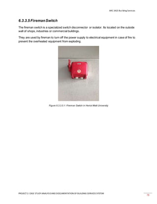
o Fireman Switch. (n.d.). Retrieved November 21, 2015, from
https://library.e.abb.com/public/d201a5400aa23001c1257a52004a7
2d9/2CMC341001L0201.pdf](https://image.slidesharecdn.com/revisedbservice-151211040945/85/Revised-bser-vice-90-320.jpg)


![[ARC2423] Building Services- Project 2 : The inspiration and the intervention](https://cdn.slidesharecdn.com/ss_thumbnails/p2-buildingservice-131213000334-phpapp02-thumbnail.jpg?width=640&height=640&fit=bounds)


