1. Serial In - Serial Out
Shift Registers
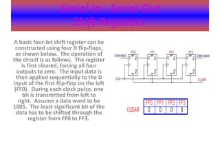
A basic four-bit shift register can be constructed using four D flip-flops, as shown below. The operation of the circuit is as follows. The register is first cleared, forcing all four outputs to zero. The input data is then applied sequentially to the D input of the first flip-flop on the left (FF0). During each clock pulse, one bit is transmitted from left to right. Assume a data word to be 1001. The least significant bit of the data has to be shifted through the register from FF0 to FF3.
2. Serial In - Parallel Out
Shift Registers
For this kind of register, data bits are entered serially in the same manner as discussed in the last section. The difference is the way in which the data bits are taken out of the register. Once the data are stored, each bit appears on its respective output line, and all bits are available simultaneously. A construction of a four-bit serial in - parallel out register is shown below.
3. Parallel In - Parallel Out
Shift Registers
•For parallel in - parallel out shift registers, all data bits appear on the parallel outputs immediately following the simultaneous entry of the data bits. The following circuit is a four-bit parallel in - parallel out shift register constructed by D flip-flops.
4. Shift Register Counters
•Ring Counters
•A ring counter is basically a circulating shift register in which the output of the most significant stage is fed back to the input of the least significant stage. The following is a 4-bit ring counter constructed from D flip-flops. The output of each stage is shifted into the next stage on the positive edge of a clock pulse. If the CLEAR signal is high, all the flip- flops except the first one FF0 are reset to 0. FF0 is preset to 1 instead.
5. Shift Register Counters
•Johnson Counters
•
Johnson counters are a variation of standard ring counters, with the inverted output of the last stage fed back to the input of the first stage. They are also known as twisted ring counters. An n-stage Johnson counter yields a count sequence of length 2n, so it may be considered to be a mod-2n counter. The circuit above shows a 4-bit Johnson counter. The state sequence for the counter is given in the table as well as the animation on the left.