Automatic mic adjustment using dc motor
•
1 like•65 views

Abstract Beamforming theory is used to measure the phase angle between two input signals. Automatic adjustment of height and position of MIC using dc motors. Horizontal and vertical DC motors are attached with the mic. Microphone array signal processing is to enhance and extract information carried by acoustic waves received from a number of microphones. Differently placed microphones are receiving more or less the same signal but with a small time shift. The time delay estimation is calculated using LabVIEW software. Keywords - MEMS microphones, beamforming, source localization, DC motor

Recommended
Recommended
More Related Content
What's hot
What's hot (20)
Viewers also liked
Viewers also liked (17)
Similar to Automatic mic adjustment using dc motor
Similar to Automatic mic adjustment using dc motor (20)
More from eSAT Journals
More from eSAT Journals (20)
Recently uploaded
Recently uploaded (20)
Automatic mic adjustment using dc motor
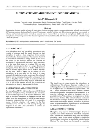
- 1. IJRET: International Journal of Research in Engineering and Technology eISSN: 2319-1163 | pISSN: 2321-7308 _______________________________________________________________________________________ Volume: 04 Issue: 02 | Feb-2015, Available @ http://www.ijret.org 417 AUTOMATIC MIC ADJUSTMENT USING DC MOTOR Raja T1 , Thilagavathi B2 1 Assistant Professor, Annai Mathammal Sheela Engineering College, Tamil Nadu – 636 004, India 2 Assistant Professor, Karunya University, Tamil Nadu – 641 115, India Abstract Beamforming theory is used to measure the phase angle between two input signals. Automatic adjustment of height and position of MIC using dc motors. Horizontal and vertical DC motors are attached with the mic. Microphone array signal processing is to enhance and extract information carried by acoustic waves received from a number of microphones. Differently placed microphones are receiving more or less the same signal but with a small time shift. The time delay estimation is calculated using LabVIEW software. Keywords - MEMS microphones, beamforming, source localization, DC motor ---------------------------------------------------------------------***----------------------------------------------------------------- 1. INTRODUCTION In the microphone array, one microphone is considered to be a point of reference and the sound observed on that microphone is used as a base comparison for the sounds observed on the other microphones. The direction of arrival of sound waves at an array is simply defined by the vector that points in the direction opposite the direction of propagation; it points towards the source. When the source is in the near field, there is a unique DOA at each microphone location, just as there is a unique direction of propagation. When the source is in the far field, the wave fronts at the array appear planar, and all DOAs at the array are the same. While a DOA can be defined at each microphone, or at any point on the array, it is most commonly defined relative to the array origin. The origin of the array can be arbitrarily chosen and is not necessarily the same as the global origin. Usually, it is chosen to be the center of the array. Once the array origin is established, the DOA to this origin depends only on the location of the source and is the same for both near and far fields. 2. MICROPHONE ARRAY STRUCTURE The microphones M3-M1-M2 form the array with M1 being the center microphone. Using microphones, the time delay of arrival and also position of dc motor is determined. The angle of arrival θ1 is measured in clockwise direction with respect to the line perpendicular to M1-M2 axis and passing through the midpoint of the axis. Angle θ2 is measured in counter clockwise direction with respect to the line perpendicular to M1-M3 axis and passing through the midpoint of the axis. This convention is chosen for experimental convenience. Fig 1: Microphone array The signal from the source reaches the microphones at different times. This is because the sound wave has to travel different paths to reach the different microphones. Consider the microphone pair M1-M2.These microphones form a part of ’L’ shaped microphone array with a distance d between adjacent microphones. Microphone array processing is an emerging technique and plays an important role in a practical solution. With continued investigation over the last two decades, the time delay estimation based localization has become the technique of choice. The system consists of two or more microphones with the direction of an incident sound wave calculated from the difference in arrival times at the respective microphones in the array. 3. BEAMFORMING THEORY Microphone arrays are used for determining the direction of a present sound field or the location from which it originates from. The array and the following array signal processing is also called a beam former and the technique is called beam- forming. Beam forming can be described as a kind of spatial filtering. The beam former can be steered in a particular
- 2. IJRET: International Journal of Research in Engineering and Technology eISSN: 2319-1163 | pISSN: 2321-7308 _______________________________________________________________________________________ Volume: 04 Issue: 02 | Feb-2015, Available @ http://www.ijret.org 418 direction/area in order to enhance signals from that direction and suppress signals from all other directions. The basic idea of inter-aural time difference is based on time shifts between received signals due to the finite speed of sound. By integrating the data from a multitude of microphones, the redundancy of a large array can be exploited to improve localization in the presence of adverse acoustic effects such as reverberation and background noise. Once these signals are time-aligned, they are summed together to form a single output signal. More sophisticated beamformers apply filters to the array signals as well as this time alignment. The derivation of the filters in these filter-and-sum beamformers is what distinguishes one method from the other. More sophisticated beamformers apply filters to the array signals as well as this time alignment. 4. CORRELATION Correlation coefficients (denoted r) are statistics that quantify the relation between X and Y in unit-free terms. When all points of a scatter plot fall directly on a line with an upward incline, r = +1; When all points fall directly on a downward incline, r = -1. Such perfect correlation is seldom encountered. Weak correlations are associated with scatter clouds that adhere marginally to the trend line. The closer r is to +1, the stronger the positive correlation. The closer r is to -1, the stronger the negative correlation. Cross-correlation measures the similarity between two time series. Find the features of an unknown time series by computing the cross correlation between the unknown time series and a known time series. Using cross correlation theory, the time delay between the two signals are calculated and also phase angle is measured. Maximum peak location and amplitude are determined by using peak detector. When array size is connected with the maximum location of peak detector then total number of maximum peaks is displayed in the front panel of the LabVIEW.The practical calculations of time delay is accurate when compare to the theoretical calculations. 5. PIEZOELECTRIC MEMS MICROPHONE This microphone uses a diaphragm design consisting of a 230 nm oxide/nitride diaphragm, aluminum electrodes, and a 4.3 µm thick piezoelectric layer. The piezoelectric material is quite thick because it is very compliant relative to the other materials comprising the diaphragm. The stress of the oxide/nitride diaphragm is reported to be greater than 107 MPa. The signal is buffered with the p-JFET with a gain of 0.85. The microphone has a capacitance of 4 - 8 pF and a sensitivity of 0.21 mV/Pa. These microphones have a noise floor of 54.6 dBA. The authors attribute the increased performance of this microphone to the thickness of the piezoelectric material layer but note that this thickness is limited by an eventual reduction in sensitivity due to a reduction in membrane displacement. Piezoelectric material selection can have significant impact on device performance. Different piezoelectric materials exhibit vastly different qualities and it is extremely important to use the best material for a specific application. 6. RESULTS Fig 2: Cross- correlation Block Diagram in LabVIEW
- 3. IJRET: International Journal of Research in Engineering and Technology eISSN: 2319-1163 | pISSN: 2321-7308 _______________________________________________________________________________________ Volume: 04 Issue: 02 | Feb-2015, Available @ http://www.ijret.org 419 Fig 3: Front Panel for Automatic Mic Rotation in LabVIEW 7. CONCLUSION The location of sound sources estimated by acoustic source localization systems based on the signals received by microphones. Direction of sound source is determined by estimating the time delay between two microphones. Depends upon the time delay, mic would enable to rotate forward or reverse. REFERENCES [1]. E. Elka, D. Elata, and H. Abramovich. The electromechanical response of multilayered piezoelectric structures. IEEE Journal of Microelectromechanical Systems, 13:332–341, April 2004. [2]. Tony Gustafsson, Bhaskar D. Rao and Mohan Trivedi, “Source Localization in Reverberant Environments”, IEEE Transactions on Speech and Audio Processing, vol. 11, No. 6, PP 791–803, Nov 2003. [3]. Cha Zhang, Dinei Florêncio, Demba E.Ba, and Zhengyou Zhang, Maximum Likelihood Sound Source Localization And Beamforming For Directional Microphone Arrays In Distributed Meetings, IEEE Transactions on Multimedia, vol. 10, No. 3, PP. 538–548, Apr 2008. [4]. Joseph Hector DiBiase,A High-Accuracy, Low-Latency technique for talker localization in reverberant environments using microphone arrays, Brown University. [5]. Xiaohong Sheng and Yu-Hen Hu , Maximum Likelihood Multiple-source Localization Using Acoustic Energy Measurements, IEEE Transactions on Signal Processing, VOL. 53, NO. 1, PP 44 - 53, Jan 2005. [6]. Wing-Kin Ma, Ba-Ngu Vo, S. Singh, and A. Baddeley, Tracking An Unknown Time-varying Number Of Speakers Using TDOA Measurements,IEEE Transactions on Speech and Audio Processing, VOL. 54, NO. 9,PP. 3291–3304, Sept 2006. [7]. Bob Mungamuru and Parham Aarabi, Enhanced Sound Localization, IEEE Transactions on Systems, Man and cybernetics, vol. 34, No. 3, PP 1526–1540, Jun 2004. [8]. Ming Yang, Mostafa Al-Kutubi, Duc Truong Pham, “InSolidAcoustic Source Localization Using Likelihood Mapping Algorithm” , Open Journal of Acoustics, vol 10, No:1, PP 34-40, Sep 2011.