More Related Content
Similar to iaetsd Design of slotted microstrip patch antenna for wlan application
Similar to iaetsd Design of slotted microstrip patch antenna for wlan application (20)
More from Iaetsd Iaetsd (20)
iaetsd Design of slotted microstrip patch antenna for wlan application
- 1. Design of Slotted Microstrip Patch Antenna for WLAN application
Geant Michael Radje.A1
, Jeevan Kumar.R2
Geant Michael Radje.A (B.Tech,ECE), RGCET,Pondicherry
Jeevan kumar.R (B.Tech,ECE), RGCET,Pondicherry
1
geantmichael@gmail.com
2
jrjeevankumar@gmail.com
Abstract— A simple microstrip patch antenna consists of metallic
patch and ground between which is a dielectric medium called the
substrate. Microstrip patch antennas are used for communication
purposes especially in military and civil applications. In this
paper a simple microstrip patch antenna is designed and
evaluated using HFSS software at a resonant frequency of 2.4
GHz . The proposed slotted microstrip patch antenna designed at
C-band microwave frequency consist of air filled substrate with
coaxial feed requiring very low power dissipation. Recently
printed antennas have played a major role in development of
antenna at different frequency. The proposed antenna is done on
fr4(fr substrate with dielectric permittivity ɛo and the thickness ho
will provide with good omnidirectional radiation pattern. It has
advantage in simple design, Compact in size and easy in
fabrication.
Keywords— Slotted Microstrip patch antenna, fr4(frame
resistive) substrate , Stripline feeding, HFSS software.
I.INTRODUCTION
Antenna is a transducer designed to transmit or receive
electromagnetic waves. Microstrip antennas have several
advantages over conventional microwave antenna and
therefore are widely used in many practical applications.
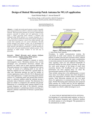
Microstrip antennas in its simplest configuration are shown
in Fig1. It consists of a radiating patch on one side of
dielectric substrate (Єr≤10), which has a ground plane on
other side. Microsrtip antennas are used for number of
wireless applications such as WLAN, Wi-Fi, Bluetooth and
many other applications. A simple microstrip patch antenna
consists of a conducting patch and ground plane between
them is a dielectric medium called the substrate having a
particular value of dielectric constant. The dimensions of a
patch are smaller as compared to the substrate and ground.
Dimensions of a microstrip patch antenna depend on the
resonant frequency and value of the dielectric constant.
Microstrip antenna is a printed type antenna consisting of a
dielectric substrate sandwiched in between a ground plane
and a patch.
Figure 1. Microstrip antenna configuration
1.1 Microstrip Patch Antenna
Nowadays, in mobile communication systems, the
requirement of small sized antenna for miniaturization
purpose of mobile units has been increased. Hence, reduced
size and enhanced bandwidth are the major considerations
in microstrip antennas for practical applications. Therefore,
study regarding small size and enhanced bandwidth of
microstrip antenna has been greatly increased. In the past
few years, great progress in the design of small sized
microstrip antenna with broadband and gain enhanced
performance has been reported hence we select the
microstrip patch antenna for WLAN application.
These include cutting slots in the radiating patch, in recent
times many novel planar antennas have been designed to
satisfy the requirements of mobile cellular communication
systems. Some Microstrip antennas are also very good
choice for applications in communication devices. In this
paper, Slotted Microstrip patch antenna has been proposed
which operates for 2.4GHz band for WLAN application.
Radiating patch and a partial ground. The proposed antenna
has compact size which is added advantage to use it.
II. ANALYSIS OF MICROSTRIP PATCH ANTENNA
For designing of a microstrip patch antenna, we have to
select the resonant frequency and a dielectric medium
for which antenna is to be designed. The parameters to
be calculated are as under.
ISBN-13: 978-1540513212
www.iaetsd.in
Proceedings of ICAET-2016
©IAETSD 201648
- 2. Figure2. Structure of a Microstrip Patch Antenna
Width (W): The width of the patch is calculated using
the following equation
Where, 𝑊 = Width of the patch
𝐶0= Speed of light
𝜀 𝑟= value of the dielectric substrate
Effective refractive index: The effective refractive index
value of a patch is an important parameter in the
designing procedure of a microstrip patch antenna. The
radiations traveling from the patch towards the ground
pass through air and some through the substrate (called
as fringing). Bath the air and the substrates have
different dielectric values, therefore in order to account
this we find the value of effective dielectric constant.
The value of the effective dielectric constant (𝜀 𝑟) is
calculated using the following equation:
Length: Due to fringing, electrically the size of the antenna
is increased by an amount of (ΔL). Therefore, the actual
increase in length (ΔL) of the patch is to be calculated
using the following equation:
Where ‘h’= height of the substrate.
The length (L) of the patch is now to be calculated using
the below mentioned equation:
Length (Lg) and width (Wg) of ground plane: Now the
dimensions of a patch are known. The length and width of
a substrate is equal to that of the ground plane. The length
of a ground plane (Lg) and the width of a ground plane
(Wg) are calculated using the following equations:
III. DESIGNED ANTENNA AND ITS PARAMETERS
After an exhaustive literature review of the papers ranging
from the year 1996-2014, there have been different types of
approaches for making the small size antenna which are
used only for WLAN applications. For WLAN technology
there are various antennas used at 2.4GHZ frequency, like
Micro strip patch antenna or PCB antenna, Chip antenna,
Helical Wound Stub antenna, Low Profile Dome antenna,
Dipole antenna with flying lead etc.
In this paper several parameters of Slotted Microstrip patch
Antenna resonating at frequency 2.4GHZ have been
investigated using HFSS software. The geometry of patch
antenna is shown in figure-1.
The design specifications for patch antenna are:
Substrate permittivity (ξr) = 4.2
Substrate thickness (h) = 1.6 mm.
Length of patch (L) = 50.12 mm.
Width of patch (W) = 50.12 mm.
Slot Length(L) = 20.24mm
Slot Width(W) = 20.24mm
Figure 3. Rectangular microstrip patch antenna
resonating at 2.4 GHZ.
ISBN-13: 978-1540513212
www.iaetsd.in
Proceedings of ICAET-2016
©IAETSD 201649
- 3. IV. SIMULATION RESULT DISCUSSION
HFSS simulation software was chosen to simulate the
structures shown in the Figures. The VSWR and Radiation
was obtained from simulation. The simulated result of
Slotted Microstrip Patch Antenna are shown below.
The figure-4 below shows the Voltage Standing Wave
Ratio (VSWR) versus frequency graph of the designed
antenna. The VSWR is minimum (equal to 1.886031) at 2.4
GHz
Figure 4. VSWR
The following figure-5 shows the 2D Radiation pattern of
the antenna.
Figure 5. 2D Radiation pattern
The following figure-6 shows the gain pattern of the
antenna in the farfield. The direction of the maximum gain
of the antenna is above the patch (i-e, in the direction of
theta), while minor lobes are on the opposite side
Figure 6. 3D Radiation Pattern
V. CONCLUSION
The research motivation of this project is to design slotted
Microstrip patch antenna for WLAN application which
operates in S-band at 2.4 GHz. HFSS simulator is used for
design and simulation of patch Antenna. The Slotted patch
antenna with 50ohms line feed has been designed. The
VSWR of the designed antenna is 1.88, the radiation
Efficiency at 2.4 GHz is achieved. The gain and bandwidth
of single element patch shows the path of further
experiments with arrays of antennas and in the case of dual
polarization. Results & analysis of this antenna indicates
that it is applicable in miniature devices, simple design &
compact size as added advantage, which can easily be used
in embedded wireless system applications.
REFERENCES
[1]. Chandan Kumar Ghosh and Susanta Kumar Parui “Design, Analysis
and Optimization of A Slotted Microstrip Patch Antenna Array at
Frequency 5.25 GHz for WLAN-SDMA System” International Journal on
Electrical Engineering and Informatics - Volume 2, Number 2, 2010
[2]. Jaswinder Kaur, Rajesh Khanna “Co-axial Fed Rectangular Microstrip
Patch Antenna for 5.2 GHz WLAN Application” Universal Journal of
Electrical and Electronic Engineering 1(3):94-98, 2013 DOI:
10.13189/ujeee.2013.010306 http://www.hrpub.org
[3]. J. G. Vera-Dimas, M. Tecpoyotl-Torres, P. Vargas-Chable, J. A.
Damián-Morales J. Escobedo-Alatorre and S. Koshevaya “Individual
Patch Antenna and Antenna Patch Array for Wi-Fi Communication”
Center for Research of Engineering and Applied Sciences (CIICAp),
Autonomous University of Morelos State (UAEM), 62209, Av.
Universidad No.1001, Col Chamilpa, Cuernavaca, Morelos, México
[4]. Ajay Singh and S. C. Gupta of Dehradun Institute of Technology,
Dehradun (India), “Review and Survey of Broadband Microstrip Patch
Antennas”, 2012
[5]. Ray, K. P, “Broadband Microstrip Antennas”, Artech House antennas
and propagation library, 2003.
[6]. C.A. Balanis, “Antenna Theory, Analysis and Design,” John Wiley
&Sons, New York, 1997.
[7]. R.Garg, P.Bhartia, I.Bahl, and A.Ittipiboon, Microstrip Antenna
Design Handbook Antennas, John Wiley, 1997
[8]. A. A. Abdelaziz of Department of Electronics and Communications
Faculty of Engineering Misr University for Science and Technology,
paper on “Bandwidth Enhancement of Microstrip Antenna”, 2006
[9]. Md. MarufAhamed, Kishore Bhowmik, Abdulla Al Suman “Analysis
And Design of Rectangular Microstrip Patch Antenna On Different
Resonant Frequencies For Pervasive Wireless Communication”
INTERNATIONAL JOURNAL OF SCIENTIFIC & TECHNOLOGY
RESEARCH VOLUME 1, ISSUE 5, JUNE 2012.
ISBN-13: 978-1540513212
www.iaetsd.in
Proceedings of ICAET-2016
©IAETSD 201650