
Recommended
More Related Content
What's hot
What's hot (16)
Similar to INTRODUCTION TO CATHODIC PROTECTION
Similar to INTRODUCTION TO CATHODIC PROTECTION (20)
Recently uploaded
Recently uploaded (20)
INTRODUCTION TO CATHODIC PROTECTION
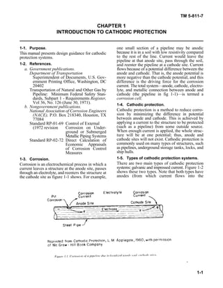
- 1. TM 5-811-7 1-1 CHAPTER 1 INTRODUCTION TO CATHODIC PROTECTION 1-1. Purpose. one small section of a pipeline may be anodic This manual presents design guidance for cathodic protection systems. 1-2. References. a. Government publications. flows because of a potential difference between the Department of Transportation anode and cathode. That is, the anode potential is Superintendent of Documents, U.S. Gov- more negative than the cathode potential, and this ernment Printing Office, Washington, DC difference is the driving force for the corrosion 20402 current. The total system—anode, cathode, electro- Transportation of Natural and Other Gas by lyte, and metallic connection between anode and Pipeline: Minimum Federal Safety Stan- cathode (the pipeline in fig 1-1)—is termed a dards, Subpart 1 - Requirements Register, corrosion cell. Vol 36, No. 126 (June 30, 1971). b. Nongovernment publications. National Association of Corrosion Engineers (NACE), P.O. Box 218340, Houston, TX 77084 Standard RP-01-69 Control of External (1972 revision Corrosion on Under- ground or Submerged Metallic Piping Systems Standard RP-02-72 Direct Calculation of Economic Appraisals of Corrosion Control Measures 1-3. Corrosion. Corrosion is an electrochemical process in which a current leaves a structure at the anode site, passes through an electrolyte, and reenters the structure at the cathode site as figure 1-1 shows. For example, because it is in a soil with low resistivity compared to the rest of the line. Current would leave the pipeline at that anode site, pass through the soil, and reenter the pipeline at a cathode site. Current 1-4. Cathodic protection. Cathodic protection is a method to reduce corro- sion by minimizing the difference in potential between anode and cathode. This is achieved by applying a current to the structure to be protected (such as a pipeline) from some outside source. When enough current is applied, the whole struc- ture will be at one potential; thus, anode and cathode sites will not exist. Cathodic protection is commonly used on many types of structures, such as pipelines, underground storage tanks, locks, and ship hulls. 1-5. Types of cathodic protection systems. There are two main types of cathodic protection systems: galvanic and impressed current. Figure 1-2 shows these two types. Note that both types have anodes (from which current flows into the
- 2. TM 5-811-7 1-2 electrolyte), a continuous electrolyte from the zinc because of these metals’ higher potential anode to the protected structure, and an external compared to steel structures. metallic connection (wire). These items are b. Impressed current systems. Impressed current essential for all cathodic protection systems. cathodic protection systems use the same elements a. Galvanic system. A galvanic cathodic pro- structure is protected by applying a current to it tection system makes use of the corrosive poten- from an anode. The anode and the structure are tials for different metals. Without cathodic protec- connected by an insulated wire, as for the galvanic tion, one area of the structure exists at a more system. Current flows from the anode through the negative potential than another, and corrosion electrolyte onto the structure, just as in the galvanic results. If, however, a much less inert object (that system. The main difference between galvanic and is, with much more negative potential, such as a impressed current systems is that the galvanic magnesium anode) is placed adjacent to the struc- system relies on the difference in potential between ture to be protected, such as a pipeline, and a the anode and structure, whereas the impressed metallic connection (insulated wire) is installed current system uses an external power source to between the object and the structure, the object will drive the current, as figure 1-2b shows. The become the anode and the entire structure will external power source is usually a rectifier that become the cathode. That is, the new object cor- changes input a.c. power to the proper d.c. power rodes sacrificially to protect the structure as shown level. The rectifier can be adjusted, so that proper in figure 1-2. Thus, the galvanic cathodic protec- output can be maintained during the system’s life. tion system is called a sacrificial anode cathodic Impressed current cathodic protection system protection system because the anode corrodes anodes typically are high-silicon cast iron or sacrificially to protect the structure. Galvanic graphite. anodes are usually made of either magnesium or as the galvanic protection system, only the