Variable Frequency on Wireless Power Transfer for Pacemaker using Embedded Te...
Electrical System Design Initial
1. Ministry of Awqaf and Islamic Affairs
Introductionof Electrical systemdesigncourse onElectrical Powersystem.
Introduction to Design courseon ElectricalPower System.
Criteria : The design course based on theory and the most practical point of view.
General :
1.0 Basic Design consideration:
1.1. The power supply system shall be designed to provide safe ,economical operation and ensure safety
Of equipments and persons. The power system should be economic, reliable, long service life and
panels should be simple in operation and maintenance.
1.2 The following factors shall be taken into consideration while designing the Electrical system:-
a) Safety : Personnel safety, efficiency of operation and precaution of equipments are the most
vital factors to be considered while designing the electrical system.
b) Reliability : Reliability of electrical supply is essential for the continuous operation. The electrical
system shall be designed so that faults can be isolated with minimum disturbance to
the system as well as short time.
c) Easy operation : Simplicity of operation is very important factor in achieving safe and reliable
electrical system. The operation should be simple as possible to meet the
requirements.
d) Voltage Fluctuation : Voltage shall be maintained within the equipments tolerance limit under
all load condition in order to enhance the service life of electrical equipments.
e) Flexibility : Flexibility of electrical system means the adaptability to meet the various requirement.
utilization voltage, equipment rating, space for additional equipments, capacity for
increased load, spare capacity for future load.
f) Installation :Power installation shall be designed to give enough power ,easy control of
electrical devices. materials, components, accessories used for installation shall be
identical type.
f) Maintenance : The electrical system shall be design to allow easy maintenance without major
interruption and disturbance of users.
g) Equipments: All equipments and materials selected shall be well known manufacture , spare parts
are available,manufactures are according to local and international standard.
h) Cost : Cost should be economical on the basis of initial, running and maintenance purpose.
2. Ministry of Awqaf and Islamic Affairs
Introductionof Electrical systemdesigncourse onElectrical Powersystem.
2. Source of Power Supply :
a) Normal : MEW
b) Emergency : Stand by Generator
c) Critical : UPS
3. Supply System : All electrical works, equipment, accessories, fittings shall be designed
and manufactured operate continuously in the power supply system
having the following characteristics.
a) Voltage : 415+-6% 3 phase, 4 wire
240+-6%, single phase
b) Frequency : 50 hertz+-4%
c) Neutral : Solidly earthed T.T system.
d) Fault level : 31MVA at 415 volts
e) Fault duration : 0.5 second.
4. Climate condition : The environmental condition in Kuwait are severe and shall be consider
carefully while designing the electrical power system, selecting
equipments. Electrical panels for outdoor installation shall be suitable
for continuous operation at dusty, windy and rainy weather under high
ambient temp. 50 degree centigrade and high humidity 100%.
5. Electrical Load : Load is the is key factor to design electrical power system. Type of
Electrical load are as follows :
1) General loads :
a) Dynamic load which consists of electric motors driving
rotating equipments. Loads are A/C Equipments, Lifts,
Plumbing Equipments(Pumps), Mechanical Equipments
like exhaust fan, Fresh air Fans, Smoke Fans, Central
water Heater.
b) Static load which consists of non moving type
equipments, like as cooling ,lighting, heating, small
power (socket outlet) load.
2) Critical loads : These are loads of prime importance to the safety
Of installation and operation like as computer and
Control room load ( no break power supply by UPS)
3) Essential load : These are the loads whose power loss would affect
the continuity of operation ,resulting loss of
important data and damage of equipments.
stand by Generator can be provided to take care
of this matter. Loads are Elevators, Pumps( all
kind ), Smoke Fans, Fire alarm system ,security
3. Ministry of Awqaf and Islamic Affairs
Introductionof Electrical systemdesigncourse onElectrical Powersystem.
system and Communication system. It is very import
to prepare a complete LOAD SCHEDULE for all type
of loads before starting design
6. Basic theoryof Electrical Power System : Basic theory of Electrical Engineering is very
important to design of electrical power system
. So, here some important tropics which are related
to design is review
Tropics are as follow :
1) Ohm, s Law
2) Voltage
3) Current
4) Frequency
5) Resistance
6) Inductance
7) Capacitance
8) Power
9) Voltage Drop
10) Power Factor
11) Conduit
12) Conductor (cables, wire )
13) Protection
14) Measuring Instrument
15) Method of Installation
16) Transformer
17) Motor
18) Lux calculation
19) Earthing system
20) Switchgear
21) Sub-Station
Ohm, s Law The potential Difference (voltage) across an ideal conductor (copper) is proportional to
the current through it. The constant of proportionality is called Resistance.
So, V ∞ I or V=IR, Where V= voltage, I= Current, R= Resistance.
Voltage : Voltage is the electrical force that causes free electron to move one atom to a
another Voltage is also called Potential, Potential difference, Potential drop,
Electromagnetic force. Its unit is volt.
Current : Current is the rate of flow of charge or in an electrical circuit, the number of
electrons are moving is called the amerage or the current and its unit is
ampere (A).
Frequency : In ac circuit the current wave how many times change it direction is known as frequency.
It units is hertz (f ).
4. Ministry of Awqaf and Islamic Affairs
Introductionof Electrical systemdesigncourse onElectrical Powersystem.
Power : The power is energy produced by one second or electric power is the rate of doing
electrical works . It units is kilowatt and symbol is P.
Resistance : Resistance is the retarding force in a conductor which opposes the flow of current. The
voltage is equivalent to water pressure, the current is equivalent to the flow rate, the
resistance is like the pipe size.
R= p L /A where R is the resistance of conductor ,L is the length
Of Conductor, p is resistivity of conductor.
Or, R ∞ 1/A if L ,p are constant.
So, Resistance is inversely proportional to the cross-section of conductor.
Resistance is responsible for resistive loss in a electrical circuit. It loss as a
form of heat.
From ohm, s law current I= V/R
Or, I ∞ 1/R, Current is inversely proportional to R, if V is constant
If R is low the current I is high, so by increasing the cable size load
current can be increased.
Inductance : Inductance is that property of a conductor (coil) which oppose to build up current before
voltage ,first voltage build up due to inductance property, then flow in the circuit. Voltage
is lead and current is lag. Most of bulk loads are lagging power factor due to inductance.
It symbol is L and unit is henry.
Capacitance : Capacitance is that property of a conductor which oppose to build up voltage. But
storage energy as a charge. In a capacitive circuit first current flow then voltage. It
symbol is C and unit is microfarad
Power : The capacity to do the works is known as power, energy produced a electrical circuit in
one second, electric power is rate of doing electrical works. It unit is P and unit is watt.
For a d.c circuit power P= V x I but in a.c circuit power P= V x I x P.F for single phase
For three phase circuit
Power P= √3 V X I X P.F (P.F= power factor)
Or, P ∞ P .F ,Power P is proportional power factor. So, by increasing the power factor
apparent power can be increased.
Voltage Drop : It is the potential difference between two point in electrical circuit. Voltage drop is the
reduction in voltage in the passive element of an electrical circuit. The in the A.C circuit
the product of current I and impedance Z, V.P=I X Z .
Power factor : The cosine angle between voltage and current in an a.c circuit is known as power fa.
Factor Or it the ratio of real power to apparent power. Power factor is very important
in Electrical system. unit is microfarad. b) At constant voltage the load current will
be more , this increase conductors size. c) Voltage drop is high due higher load
current d) Poor voltage regulation. Now a day energy is saving by improve the power
factor ,like by capacitor banks.
5. Ministry of Awqaf and Islamic Affairs
Introductionof Electrical systemdesigncourse onElectrical Powersystem.
Conduit : An electrical conduit is an electrical piping used for safety, protection and route
of electrical wiring. Conduits are classified by the wall thickness ,mechanical
stiffness and material used to make the tubing. For ,electrical works generally
PVC, UPVC ,GI , and flexible are used on the basis of application. Different
sizes of conduits are 20mm, 25mm, 38mm, 50mm ,UPVC pipes sizes are
3”, 4” and 6”.
Conductors : Conductors (cables & wires ) of electricity are materials that electricity pass through
them with safety. Copper is good conductor, it has so many advantages rather than
other conductor, like aluminum, silver and gold. Advantages bearing temperature is
high, current carrying capacity is very high, conductivity is very high and mechanical
stress is very high. Generally XLPE and PVC insulated cables are used in Kuwait.
XLPE Cable : XLPE (Cross linked polyethelene) cables are mostly in Kuwait. The
Cables consists of a) conductor b) Insulation c)PVC sheath d)Armour
Other material used for bedding and serving .
a) Conductors : The function of conductors is to carry the current.
Conductors made of pure copper or alumunium. The
Diameter or size of conductor depend upon current
Carrying capability, conductors are solid , stranded.
Stranded conductors are more flexible. Cross section
Of conductors are circular and oval shape.
b ) Insulation : The function of insulation is to separate phase and
Earth conductors from each other. Xlpe insulation are
white in colour, for phase identification Red, Yellow,
Blue, Black and Green.
c ) PVC sheath : In order to protect the cables from moisture, water
damaging liquids in the soil and atmosphere PVC
sheath is used.
d ) Armour : Armour which consists of one or two layer of
galvanized steel wire is provided the cables from
mechanical injury during lying and use as earth.
c) Bedding : A layer of bedding which consists of fibrous material is
applied over the XLPE insulation to protect cables
from armour and provide smooth bed for armouring.
c ) Serving : In order to protect the armouring from atmospheric
condition ,a layer of fibrous material is proved over
the armour.
Protection : Protection or Trip system is the main feature of a electrical system. Protection criteria
should have following characteristics a) Reliability : Perform correctly when required
operation and avoid unnecessary
interruption.
b) Speed :Disconnect the fault at shortest time
6. Ministry of Awqaf and Islamic Affairs
Introductionof Electrical systemdesigncourse onElectrical Powersystem.
c) Selectivity : Ability to locate the fault and trip
the minimum number of Breakers
to isolate only fault.
d) Economics :Maximum protection at optimum
Cost.
e) Simplicity :Minimum equipment and circuitry
for the required protection.
The main protection system are Short circuit , Over-current, Earth fault,
Under voltage protection. When a fault occurs in a electrical circuit, first in CT or
Toroid current increases, relay sense this increased current and energized the relay
coil which in turn closed the tripping circuit ( normally tripping circuit is open ) then
trip coil energized and pull the breaker down by magnetic induction.
Measuring Instruments : The device which are used to measure parameters of electrical system like
Current ,voltage ,frequency and power are called measuring instrument.
Method of Installation : Installation method of complete electrical works is a important factor while
design the electrical works. It define how to execute the whole electrical
works to finalized the installation, it require coordination with other services
like civil Architecture, Air-condition ,mechanical and plumbing works.
Light fitting fixing method, arrangement depend on the basis false ceiling
type whether it is recessed or suspended type or ceiling mounted or
Latch to ceiling or wall mounted.
Cables may be laid in underground or in cable tray suspended from ceiling
.
Transformer : Transformer is the static device which transfer a.c energy from one level to
another at the same frequency and power factor through electromagnetic
induction .Transformers are used in transmission and distribution system
in consumer premises to step up and step down voltage. Power transformers
are used to get various voltage in Sub-Station.
It normally consists of a ferromagnetic core and two or more coil or
windings. When one of the winding (primary) is connected to a.c supply ,
alternating current magnetic flux is produced in the core. The flux linkage
of other windings on the same core alternates. Thereby e.m.f. of same
frequency is induced in other windings called secondary windings. The
e.m.f. is induced in the transformer by electromagnetic induction of
alternating magnetic flux. Power transformer rated 11/0.415kv is normally
is used to provide power supply in project.Kuwait transformer rating are
1000 KVA ,1250 KVA and 1600 KVA.
7. Ministry of Awqaf and Islamic Affairs
Introductionof Electrical systemdesigncourse onElectrical Powersystem.
Electrical Motor : Motor is rotating device which convert electrical energy to mechanical
energy. Main part of a motor are stationary stator and rotating rotor.
The motor have three phase distributed a.c. winding on stator ,rotor has a
closed short-circuited winding. When three-phase a.c. supply is given to
stator winding, the resulting stator magnetic flux formed by circulating
current goes on varying in magnitude and direction with respect to each coil
with time at synchronous speed. As the rotor has closed short-circuited
winding , its induced emf in rotor produced short-circuited rotor current.
A current carrying conductor placed in rotating magnetic field experiences
torque. So, the rotor conductors carrying induced currents placed in rotating
magnetic field experiences torque. Motor are mainly two type induction
motor for bulk load and synchronous motor for light load constant speed.
Basically , motor used as a drive unit with pump such as Booster pump
Water transfer pump, Irrigation pump ,submersible pump, domestic water
pump ,fire fighting water pump and jockey pump.
Lux Calculation : Lux calculation is a technique to find out the total number of light fittings are
required for a room on the basis of light fitting type ,installation method ,
working Plane and mounting height. Later chapter detail lux calculation will
discussed.
Earthing system : To protect the personnel and equipments earthing is very important. By
proper earth human life and equipments damage can be save. so, all metal
part involving with the electrical system must be earthed for safe and secure
operation of electrical system. From the soil test report ,soil resistivity can be
find out. Earth resistance must be less than one ohm for ring earth. By
calculation total number of earth electrode can find out to get resistance
value less than one ohm. When fault occurs short-circuit current is very high,
so , low resistance path is highly required to clear fault current in short time.
Switchgear : The apparatus used for switching ,controlling ,protecting ,the electrical circuit
and equipment is known as switchgear. The main parts of switchgear are
Enclosure, Busbar, Breakers (MCCB), control, protection , measuring devices
Low voltage switchgear are three type :
8. Ministry of Awqaf and Islamic Affairs
Introductionof Electrical systemdesigncourse onElectrical Powersystem.
1) Cubical type (MSB ,fixed type)
2) Cellular type (MLTB ,fixed and draw out type)
3) Metal Clad type (draw out type)
In MSB all MCCBs are fixed to common centrally busbar in one enclosure.
from central busbar different rating MCCB are tape out for different feeder. DBs
SMSBs, S/Fs feed from MSB. If the building is multi-stored then each floor
have separate MSB. DB (distribution board) are used to control, protection &
switching of small power load like Light fitting ,small power socket outlet for
Kitchen equipments, home appliances’ and office equipments .
S/Fs is final device, power supply given to electrical equipments like a/c
package unit ,Smoke & fresh air fan, various pump motors via through it for
safe and secure operation & maintenance.The rating of S/F depend on
equipments load and type of load. Most of S/F are outdoor type and located
nearby equipments. The S/F used only for short circuit protection
.
Where as in MLTB (Main Low Tension Panel) enclosure have facility of
separate section with individual compartment housing incoming and outgoing
feeder. Low tension panel provide power supply to all feeder of project. LT
panel size depend on total connected MSBs ,EMSBs ,MCC ,S/F.s ,FP etc feed
from it. The output single core cables ( LV ) side of power transformer is
connected to incoming ACB of LT panel.
ATS (Automatic Transfer Switch : Automatic transfer switch is an electrical switch that reconnects
Electric power source from its primary source to a standby source
(Generator) automatically. An ATS is often installed where a backup
Generator is located ,so that generator may provide temporary
Electric power if the main source is fails.
It senses when voltage on the utility falls below predetermined limits
then initiates gen set start up. It transfer load to the gen set when the
engine has sufficiently warmed up and the generator reached
operating voltage and frequency. It also returns the to the utility
(main supply) when the utility power is restored.
ATS also provides a timer so the engine runs long enough to warm
up fully. ATS command the generator to turn off after specified
amount of “cold down “ time generator will completely stop.
There are two type of Automatic transfer switch, Circuit breaker and
Contactor. The circuit breaker type has two interlocked circuit
Breakers, so only one breaker can be closed any time.
The contactor type is simpler that is electrically operated and
Mechanically held. It operates faster than circuit breaker type, which
reduces transfer time. Rating of ATS are from 100A to 2500A.
9. Ministry of Awqaf and Islamic Affairs
Introductionof Electrical systemdesigncourse onElectrical Powersystem.
Generator :Generator is a machine which convert mechanical energy to electric energy.
Generator components are prime mover, Stator and Rotor. Prime mover is the
drive unit which rotate the generator shaft.
Stator is the stationary part of generator. The has three phase distributed winding in
Armature slot. The e.m.f induced in armature coil when rotating magnetic field of
rotor cuts it.
Rotor is the moving part of the generator, rotor has d.c field winding which is excited
by d.c current The rotor either Salient pole type (low speed generator ) or Cylindrical
type (high speed generator ).
According to the faraday,s law of electromagnetic induction whenever a conductor
cuts magnetic flux the emf induced in the conductor (coil ) is given by the rate of
change of flux linkage of the coil. The value of emf generated depend on three thing
a) Numbers of turn in the coil
b) Strength of the field
c) Speed at which coil or magnetic filed rotate.
The induced emf is given by
E.M.F =n Φ Km
Where
Km = design constant
n = Speed in rpm
Φ = Flux per pole
Magnetic flux Φ is proportional to field excitation If.
Φ∞If
So, E ∞Φ∞If
A diesel generator is the combination of diesel engine (prime mover )
With an electric generator ( Alternator ) to generate electric energy.
Diesel generator are best due best due to their longevity and lower operating
Cost.
Generator has three rating a) Stand by b) Prime c) Continuous.
A stand by gen set is used is a back up to normal utility power. Standby
Units are used when normal utility power is not available and will not used
Frequently. Another word for Stand by is “Emergency “.
Prime rated generator is required when there is no other source .Any
Generator that is every day or a fixed schedule to provide power is considered
A prime power genera tor .Another word for prime Is” continuous “.Generators
have several rating from 50KVA upto 2500KVA.
10. Ministry of Awqaf and Islamic Affairs
Introductionof Electrical systemdesigncourse onElectrical Powersystem.
Sub-Station : Sub-Station provide the power supply to project. The electrical panel like as
HT & LT, Power transformer, capacitor bank are equipped in Sub-Station.
So, Sub-Station is very important on basis of dimension and location at
design stage. Electrical engineer has sole responsibility to coordinate with
Architecture,Civil and other services engineers to ensure incoming & outgoing
HT cables, unloading HT & LT panel ,Transformers in Sub-Station without any
interruption of the others services. Transformers room should be in between
HT room and LT room to easy HT cables acces to Transformer and LT cables
out from Transformer to LT panel incoming ACB. It is responsibility of Elec.
Engineer to prepare Sub-Station equipment layout drawing and handover to
Architecture. Other important thing is Electrical rooms dimension and location.
If the building is multi-stored then it is advisable each floor has separate
Electrical room at same location to easy access feeder cables from LT panel
to MSB at the different floor of the building.
Now a days,most of Sub-Stations are in basement that case if the cables riser
are inside the electrical room, then all feeder cables can pull from LT panel
to all MSB without disturbance of other services. Electrical engineer also check
all electrical room dimension to ensure enough space for fixing MSB,s & DB,s.
Generator room dimension should be suitable to accommodate Generator on
basis of its rating and others facility like daily fuel tank, pumps. Finally Sub-
Station building drawing should be approved from concern ministries.
Project Drawing Study : Project drawing study of other services is very important to design
electrical power system. Study of Architecture, Civil, Air Condition,
Mechanical, Plumbing( Drainage, Sewerage ) ,Interior design
drawing to know room identity & user requirements and choice.
Location of Air-Condition, Mechanical ,Plumbing and Irrigation
equipments nearby the power supply have to provide through
S/Fs., Furniture layout study is essential to know location & number
of power ,data Telephone socket outlets in each room False ceiling
drawing study help to select light fitting type, installation method
. Light may be recessed or ceiling mounted or suspended type
,it depend on décor type. At beginning stage Electrical engineer have
to inform Architecture Engineer,25cm space above décor is required
to fix the light fixture.
11. Ministry of Awqaf and Islamic Affairs
Introductionof Electrical systemdesigncourse onElectrical Powersystem.
Project load :Total load of the project is key for electrical system design, without this electrical
Panels(LT, MSB, EMSB, SMSB and DB ) drawing cannot be prepared. Basically
Load s are two category a) Small power load b) Bulk load (Equipment load).
Small power Load : Small power are minor load 10-25% of project load like lighting
General socket outlets load, house and office hold equipments
Load.
Bulk load : The equipments load of electro-mechanical system are bulk or
major load of the project. They are 75-90% load of project. The
equipments load are as follow ;
Air condition system load : a) The A/C system load are several
Air cooled or Water cooled chiller
System. Motor drive unit AHU give
Cool air, so ,Electrical engineer must
check data sheet of motor to know
starting current how many more
times of running current to star
delta or VFD panel.
b) The A/C package & DX unit ,electrical
engineer should check electrical data
sheet from manufacture catalogue.
Electrical engineer should take full
A/C equipments schedule with load
from HVAC engineer.
Mechanical equipment load : c) Electrical engineer should coordinate
with Mechanical engineer to get
equipments schedule with load for
equipment like Fresh air fans, Extract
fan, Smoke fans and Lifts.
Plumbing equipment load :d) Electrical engineer also coordinate
with Plumbing engineer to get load
schedule of plumbing equipment like
Booster, Submersible, irrigation,
12. Ministry of Awqaf and Islamic Affairs
Introductionof Electrical systemdesigncourse onElectrical Powersystem.
Lifting, hot water circulating pumps.
Central water heater , fire fighting and
Jockey pumps.
Others Load : e) The others load are (special project) Kitchen
Equipment load, swimming pool equipments
load,
Now summation of small power , bulk or equipments and others load
will be the total load of project .To get design load add 20 -25% of
project load as extra load for future. This will be final load of project
Checklist prior Design : The following item reviewing is very important for electrical system design.
a) Architecture drawing study done for electrical works requirement yes
b) A/C drawing study done for electrical works requirement yes
c) Plumbing drawing study done for electrical works requirement yes
d) Furniture layout drawing study done for electrical works requirement yes
e) False ceiling layout drawing study done for electrical works requirement yes
f) Interior design layout drawing study done for electrical works requirement yes
g) General loadschedule prepared yes
h) Air-Condition load schedule prepared yes
i) Mechanical load schedule prepared yes
j) Plumbing load schedule prepared yes
k) Emergency load schedule prepared yes
l) Total load schedule prepared Yes
m) Sub-Station equipments layout drawing completed yes
n) Electrical room equipments layout drawing completed yes
o) Generator Room equipments layout drawing completed yes
p) Electrical Shaft or Cables Riser shown in drawing yes
q) Feeder cables route from LT to all panels(MSB, EMSB etc.) finalized yes
r) Coordination meeting with others services Engineers done yes
Electrical Design : The electrical design system mainly based on :
1) Power system design
2) Lighting system design.
Power system Design : The power system design based on items are electrical panels,
Cables/wires, wiring devices.
Selection for cables : The factors need to consider to design cables size are as follows.
a) Load in KW
13. Ministry of Awqaf and Islamic Affairs
Introductionof Electrical systemdesigncourse onElectrical Powersystem.
b) Distance between source and equipment
c) Voltage drop calculation
d) Number of parallel cables run
e) Group factor ( spacing between two cables )
f) Temperature factor
g) Installation method( depth of lying cable in ground or duct )
h) Drop factor per KM ( gulf cable catalogue )
i) Soil resistivity factor of ground.
j)
k)
Example for cable size: Let us consider, a MSB has load 150KW
which is giving power supply to DB,s and S/F
Of A/C unit. Distance between MLTB to MSB is 125meter.Nos. of
parallel cables is 1 but spacing between them is 15cm, Cables buried
75 cm below direct in ground , Temperature of soil below 75 cm is 40
degree centigrade and soil resistivity at 40 degree is 0.8. What is
suitable cable size of that feeder.
We know, Group factor for 15 cm space = 0.8
Depth of lying factor at 0.75m = 1
Temperature variation at 40 degree =0.95
Soil resistivity factor =0.8
Now, Derating factor = group factor x depth of lying factor x Temperature factor x soil resistivity
=0.87 X 1X 0.95 X 0.8 =0.66
Load current = 1.732 x 150 = 259.8 amp.
Equivalent current = load current / derating factor
= 259.8/ 0.66 = 393.63 amp.
Let us consider propose cable size is 4c x 300mm.sqr cu/xlpe/pvc/swa/pvc .
Now, voltage drop = equivalent current x distance in km x drop factor / no. of parallel cables
= 393.63 x0.125 x 0.19 /1 = 9.35 volt (drop factor=0.19 gulf cable catalogue )
% of voltage drop = 9.35 x 100 /415 = 2.25 %
Voltage drop from LT panel to MSB = 2.25%
Let us consider , a A/C package unit has load 75 KW at a distance 70 m feed from MSB with cable
size is4c x50 mm xlpe.
Voltage drop for 4c x50mm cable= 1.732x 75x .070x 0.87 7.910 volt. (Drop facto =0.87 gulf cable cat)
% of voltage =7.910x100/4.15 = 1.90%
Now, total % of voltage drop = 2.25+1.9 =4.15 % which is more than Mew approved voltage drop
2.5% .
14. Ministry of Awqaf and Islamic Affairs
Introductionof Electrical systemdesigncourse onElectrical Powersystem.
In this case cable size from LT panel to MSB and MSB to S/F of A/C unit have to change,
Cable size LT panel to MSB is 2Rx 4Cx 240 mm sqr cu/xlpe /pvc/swa/pvc and MSB to A/c unit is 4Cx
95mm xlpe
Voltage drop for main cable =393.63x 0.125x 0.21/2 = 5.166 volt
Voltage drop for sub cable = 1.732x 75x 0.070x 0.45 = 4.09 volt
Total voltage drop from LT panel to final equipment A/c unit = 5.166+4.09=9.256 volt
% of voltage drop = 9.256x 100/415 =2.23% which is acceptable as per MEWregulation.
Finally, Main feeder cable is 2Rx4Cx240mm sqr. And Sub feeder cable is 4Cx95mm sqr.
Selection of Breaker (MCCB) Rating : The mould case circuit breakers (MCCB) are used as a
protection device in MSB and MLTB. Normally, it is tri-
pole breaker and breaking current capacity from 22KA
to 70KA.It is used for over-current and short circuit fault
protection. It has provision of shunt trip coil for Earth
Leakage protection. To select MCCB rating factor need
to Consider are as follow.
a) Load in KW
b) Type of load
c) Temperature derating factor (if any)
d) Breaker Type (Fixed or Adjustable)
e) Protection scheme (Over curent or
short circuit)
f) Fault level
Example : Let us consider a package unit has load 60 KW and AHU unit has load 20KW.
What are breaker rating of two cases.
Load current = 1.732X 60 = 103.92 Amp
Maximum rating of protective device= 1.45X load current=1.45X103.92=150.68 amp.
As ,most of A/c package unit fan motor rating low less than 10 HP. So, there is no
high starting current.
For, first case MCCB rating is 150 amp.(adjustable type)
Load current for AHU unit = 1.732X 20=34.64 amp.
We know, AHU unit has big size fan and it drive unit is motor whose rating is most
more than 15 HP, have high starting current. The starting current differ from
manufacture to manufacture. Consider, starting current is 2-3 times more than
running current.
Now, load current=34.64X 2.5 =86.6 amp
Maximum rating of protective device =1.15X86.6 =99.59 amp =100 amp.
( note: we consider starting current factor so, protective device factor will be low )
For, second case MCCB rating will be 100 amp.(adjustable type)
15. Ministry of Awqaf and Islamic Affairs
Introductionof Electrical systemdesigncourse onElectrical Powersystem.
Design of Lighting schemes : The lighting scheme should be such that it may,
1) Provide adequate illumination
2) Provide light distribution all over working plane as uniform as
possible
3) Provide light of suitable colour
4) Avoid glare and hard shadows as far as possible.
Type of Lighting Schemes : The interior light schemes may be classified as 1) direct lighting
2) semi-direct
Lighting
3) indirect lighting
4) general lighting.
1) Direct lighting : It is most commonly used type of lighting scheme. In this lighting scheme more
than 90 percent of total light flux is made to fall directly on the working plane with the help of
deep reflector. Though it is most efficient but hard shadow and glare. It is mainly used for
industrial and general out door lighting.
2) Semi-direct lighting : In this lighting scheme 60 to 90 percent of the total light flux is made to
fall down Wards directly with the help of semi-direct reflector, remaining light us used to
illuminate the ceiling and walls. Such a lighting system is best suited to room with high ceiling
where the high level of uniformly distributed illumination is desirable. Glare in such units is
avoided by employing diffusing globes which not only improve the brightness towards the eye
level but improve the efficiency of the system with reference to the working plane.
3) Semi-indirect lighting : In this lighting scheme 60 to 90 percent of total light flux is thrown to
the ceiling for diffuse reflection and the rest reaches the working plane directly except some
absorption by the bowl . This lighting scheme is with soft shadow and glare free. It is mainly
used for indoor light decoration purposes.
4) Indirect light : In this lighting scheme more than 90 percent of total light flux is thrown upwards
to the ceiling for diffuse reflection by used inverted or bowl reflectors. In such a system the
ceiling acts as light source and glare is reduced to minimum. The resulting illumination is
softer and more diffuse, the shadow are less prominent and the appearance of the room is
much improved over that which results from direct lighting. It is used for decoration purpose in
cinemas, theatres and hotels etc and in workshop where large machines and other
obstructions would cause trouble some shadow if direct lighting is employed.
5) General lighting : In this lighting scheme lamps made of diffusing glass are used which give
nearly equal illumination in all direction.
Lighting System Design: The following factor need to consider while design the lighting scheme.
a) Illumination level :It is vital factor as because the light incident on the
working plane depends on its value like 300lux, 500lux, higher the value
more light and lower the value less light.
b) Uniformity of illumination : The human eye adjust itself automatically to the
brightness within the field of vision .If there is a lack of uniformity pupil or
iris of the eye has to adjust more frequently and thus fatigue is caused
16. Ministry of Awqaf and Islamic Affairs
Introductionof Electrical systemdesigncourse onElectrical Powersystem.
to be occurs.
c) Colour of light : The appearance of the body colour entirely depend upon
the colour of the incident light. The composition of the light should be such
that the colour appears neutral.
d) Glare : The size of opening of the pupil of human eye is controlled by iris
If the eye exposed to a very bright source of light the iris
automatically contracts in order to reduced the amount of light
admitted and prevent damage to retina ; this reduce sensitivity
so that other object with in the field of vision can be only imperfectly
seen. This effect referred to an glare and any one feels discomfort,
eye fatigue with in the field of vision. Glare may be direct or
reflected i.e it may be come directly from the light source or it may
be reflected brightness such as desktop , nickel machine parts.
e) Shadow : In lighting installation formation of long and hard shadow cause
fatigue. Hard and long shadows can be avoided by using
number of small luminaries mounted at height not less than
2.5m
.
f) Mounting height : Mounting height of the luminaires will largely be govern
by type of building and type of lighting scheme used
coefficient of utilization factor is depend on mounting of
light fitting.
g) Spacing of luminaires : Correct spacing is of great importance to provide
uniform illumination over the whole area.
h) Colour of surrounding Area : The illumination in any room depends upon
The light reflected from the walls and ceiling.
White ceiling reflect more light as compared
to coloured ones.
i) Utilization factor :It is defined as the ratio of total lumen reaching the
Working plane to total lumen given out by the lamp. It is
value between 0 and 1.It takes into account the room
reflectance room shape, polar distribution and light out
.
j) Maintenance factor : Due to accumulation of dust, dirt and smoke on lamp
they emit less light than that they emit when they are
new ones .Similarly the walls and ceiling etc. after
being covered with dust, dirt and smoke do not reflect
the same output light which is reflected when they
are new the ratio of illumination under normal working
condition the illumination when the things are
perfectly clean is known as maintenance factor.
Its value in between 0.6 to 1.
k) Light fitting type : Light fitting selection is very important to lighting scheme
Light fitting are different type, like down light at various
watt, linear light fitting at different wattage. Lumen out-
put from the lamps of fitting is the vital to select total
17. Ministry of Awqaf and Islamic Affairs
Introductionof Electrical systemdesigncourse onElectrical Powersystem.
lumen output Factor need to consider to select fitting
type are as follows:
a) Room identity and dimension
b) Room users and utility
c) Décor or without décor
d) Room wall colour
e) Room height
f) Room floor
g) Room furniture layout
Finally, Light fitting and its control (dimming provision) depends on the Room
application and users satisfaction, proper light distribution depends on the
illumination level. Its value higher or lower has significant effect on lighting.
Method of Lighting design : 1) Manual method
a) Watt per square method
b) Lumen method.
2) Soft wire method like Dialux etc.
Watt per square method : It consist in making an allowance of watts per square meter
of area (15-30) watt/m sqr. to be illuminated according to
the illumination desired on assumption of an average figure
of overall efficiency of the system.
Lumen or light flux method : This method is applicable of source of light
provide
approximate uniform illumination on working plane.
Formula for design calculation :
No. of light fitting n=Ax E/U.Fx D.FxΦ
Where,
n= Number of light fitting
A= Area to be illuminated
E= Illumination level in lumen/m sqr.
U.F= utilization factor
D.F= Depreciation factor or light loss factor
Φ = Lumen output for one particular light fitting
Utilization factor depend on depreciation factor, reflectance factor and room index. Its value
In between 0 and 1.
Typical table for depreciation factor
Air condition office 0.8
Clean Industry 0.7
Dirty industry 0.6
18. Ministry of Awqaf and Islamic Affairs
Introductionof Electrical systemdesigncourse onElectrical Powersystem.
Typical Reflectance values
Ceiling Walls Floor
Air condition office 0.7 0.5 0.2
Industrial 0.5 0.3 0.2
Room index : The room index is a number that describes the ratio of the room length, width
height.
Formula K = Lx W/Hm(L+W)
K = Room index, (this value usually between 0.75 and 5)
Where, L = Room length
W =Room width
Hm = Mounting height of fitting (from working plane =0.75m FFL )
Utilization Factor
Reflectance Room Index K
Ceiling Wall Floor 0.75 1.00 1.25 1.5 2.0 3.0 4.0 5.0
0.5 0.3 0.2 0.3 0.37 0.42 0.46 0.52 0.59 0.63 0.66
Numbers of fitting required in axis of room
Number in length = √Total no. x L/W
Number in width = √Total no. X W/L
Spacing between each fitting : It is good practice to aim at a horizontal spacing
Between two rows approximately equal to the height of the ceiling above of working
plane.
Example of lighting calculation : Let us consider a room has width 6 m , length 8m and room
height is 4m. Room has décor zip- sum board wall white colour
and floor marble .Propose Light fitting is down light 2x 26w
and illumination level is 500 lux.
No. of light fitting n=Ax E/U.Fx D.FxΦ
Where,
n= Number of light fitting
A= Area to be illuminated
E= Illumination level in lumen/m sqr.
U.F= utilization factor
D.F= Depreciation factor or light loss factor
Φ = Lumen output for one particular light fitting
n =6x 8 x500/0.8x u.f x 1800 x 2 =24000/u.f x 2880
19. Ministry of Awqaf and Islamic Affairs
Introductionof Electrical systemdesigncourse onElectrical Powersystem.
n = 24000/u.f x 2880 = 19.84
Formula K = Lx W/Hm(L+W)
K = Room index, (this value usually between 0.75 and 5)
Where, L = Room length
W =Room width
Hm = Mounting height of fitting (from working plane =0.75m FFL )
Room index = 8x 6/3(8+6) = 1.15
Utilization factor is 0.42
Now, n= 24000/0.42x 2880 =19.84 = 20
Number in length = √Total no. x L/W = √20x 8/6=6 nos.
Number in width = √Total no. X W = √20x 6/8 =3 nos.
For uniform distribution of light ,in length fitting will be 5 nos. and in width fitting will be 4 nos.
20. Ministry of Awqaf and Islamic Affairs
Introductionof Electrical systemdesigncourse onElectrical Powersystem.
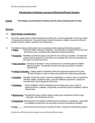
Type
Lamp: TC-DEL
2X26W
Control Gear: Electronic Ballast
IP Rating: 20
Mounting: Recessed
Description
Recessed mounted down light luminaire with compact fluorescent lamps. The luminaire
housing and ring shall be of sheet steel or die-cast aluminium with facetted or specular
high gloss pure anodized aluminium reflector, trim in white color finish or any other colors
as per site requirements. The luminaire shall operate with high frequency control gear
(Electronic Ballast) integrally or remote gearbox. The luminaires shall be installed with
fixation springs to maintain smooth and easily maintenance.
A
21. Ministry of Awqaf and Islamic Affairs
Introductionof Electrical systemdesigncourse onElectrical Powersystem.
Schedule points of DB (Distribution Board ) : Basically , DB is used to control, protection of
small power load like lights, power socket outlets,
household and office equipments. DB should
have detail information and contain the following
coloum.
a) Circuit number
b) Phase indication
c) MCB rating
d) Wire size
e) Schedule of point
f) Load description
g) Location of points
h) Controlled by
i) Phase (R,Y,B ) load in watt
j) Total load
Location of DB is very important factor , maximum distance of DB from
respective MSB should not be more than 50 meter as because of pulling main
wire inside conduit also keep load less than 30kw to avoid voltage drop and for
power & lighting load 25mmsqr or 16mmsqr is used as main wire in DB. There
are several way to select the type of DB like as Single Bus-bar, Double Bus-bar
and Split Bus-bar on the basis of load ,power supply (Single phase or Three
phase). The internal component of DB are ELCB 30ma sensitivity (Power)
,ELCB 300ma sensitivity (Light ), MCBs 10A (Light) ,MCB 15A( power socket
outlet for general load) ,MCB 20-32A for W.H, A/C unit, Freezer.For lighting
circuit wire size 1.5mm+1mmsqr,maximum load 1000 watt, for power Socket
outlet circuit wire size 2.5mm+1.5mmqr,maximum load 1500 watt and for
Equipments(W.H, A/C) circuit wire size 4mm+2.5mmsqr,maximum load 3000W
Schedule of MSB: MSB (main switch Board ) is vital panel to provide, protect,
control the power supply for DB ,SMSB and all the S/F,s of
Electro-Mechanical Equipments (a/c, plumbingmechanical).To
develop the schematic or single diagram of MSB the following
points need to be considered:
a) List out the load according to the equipments and
application.
b) Short out general (DBs) load, Air condition,
Mechanical, Pluming load separately.
c) From each load of equipments finalized the rating of
MCCB.
d) From each rating of MSB finalized the feeders cable
size.
e) From total load finalized the incoming breaker of
MSB.
f) Bus-bar rating will be 25% more from incoming main
MCCB rating.
22. Ministry of Awqaf and Islamic Affairs
Introductionof Electrical systemdesigncourse onElectrical Powersystem.
g) Prepare individual MSB for Air-condition, Mechanical
Plumbing and General small power load.
h) Load should distributed in three phase for balanced.
i) Measuring ,indication devices should shown in
drawing.
j) All pumps motors, lifts, Fresh air fans, Smoke fans
and A/c equipments outgoing MCCB should have
separate ELR of 300mm sensitivity.
Necessity of Capacitor Bank : Most of bulk load like Motor, Choke, Transformer, Electric Heater,
Compressor, Arc-welding transformer are inductive and therefore,
taking lagging current. So, in generation stage power factor is
lagging (0.8-0.85). The cosine angle in between voltage and current
is known as power factor.The power factor results in a higher energy
consumption and cost, less power distribution via network, a power
loss in network (transmission line ), a increased voltage drop in
network results poor voltage regulation, large KVA rating of
equipments ( Transformer, Alternator, Switchgear ),as because
KVA= KW/cosΦ, if KW is constant then KVA = 1/ cosΦ i.e KVA is
inversely proportional to Power factor. And also high voltage
variation in transmission lines.
To Transmit or distribute a fixed amount of power at constant voltage ,
the conductor will have to carry more current at low power factor
, this require large conductor size which is more costly due to higher
insulation cost.
Power factor improvement can be achieved by a compensation of reactive power with
Capacitor, a active compensation using semiconductor, a over excited synchronous
machine( motor or generator ).
There are so many benefits of power factor correction improvement like as :
1) Power factor correction reduces the reactive power and power cost drop in
proportion.
2) Smaller transmission losses and saving the energy.
3) Improve voltage quality and reduce conductor size for same amount of power
supply.
4) Fewer voltage drop and improve voltage regulation.
5) All Electrical equipments KVA rating reduced.
23. Ministry of Awqaf and Islamic Affairs
Introductionof Electrical systemdesigncourse onElectrical Powersystem.
Choice of compensation type : The capacitor bank or power factor corrector has two type
of compensation
a) Individual compensation : Power factor correction is wired at each single
load
b) Central compensation :There is only one bank of capacitor on the main
Power distribution switch or LT panel.
The individual compensation the capacitor and the user equipment follow the sorts
during the daily work ,power factor correction is simple with low cost.
The central compensation is best suited for system where the load fluctuates.
Key component of capacitor bank :
a) PFC controller :Modern PFC controllers are microprocessor type.
The Microprocessor analyzes the signal from current generator and
produced Switching command to control the contactors that add or
remove capacitors stages.
b) Detuned Reactor : The detuned reactor are designed to avoid any
amplification of the harmonics present on the network and protect
the capacitors. Harmonics are dangerous for capacitor connected in
PFC circuit ,especially if the capacitors operate at resonant.
frequency. The series connection of reactor and capacitor to detune
the capacitor resonant frequency help to prevent capacitor to
damage.
c) Fuse/MCCB : An HRC fuse or MCCB acts as a safety device for
short circuit protection.
d) Capacitor : Power factor correction capacitors produce the
necessary leading power to compensate the lagging reactive
power. PFC capacitors should be capable of withstanding high
inrush current by switching current.
Capacitor bank size calculation : The rating of capacitor bank can be calculated as follows ;
Qc = P*{tan[acos(pf1)}]-tan[acos(pf2)}] = P.( tanΦ1-tanΦ2 )
Where, Qc = required capacitor output in kVAr
Pf1 =actual power factor
Pf2 = target power factor
P = real power in KW
24. Ministry of Awqaf and Islamic Affairs
Introductionof Electrical systemdesigncourse onElectrical Powersystem.
The required capacitor output may be calculated as follows
Select the factor ( matching point of actual and target power factor ) k
Qc = k*P
Example :
Actual power factor = 0.70, target power factor = 0.96,
Real power ,P = 500 KW
Then , Qc = 0.73*500KW = 365 KVAR
Target Power Factor
0.7 0.75 0.8 0.85 0.9 0.92 0.94 0.96 0.98 1
Actual
power
factor
0.4 1.27 1.41 1.54 1.67 1.81 1.87 1.93 2 2.09 2.29
0.45 0.96 1.1 1.23 1.36 1.5 1.56 1.62 1.69 1.78 1.98
0.5 0.71 0.85 0.98 1.11 1.25 1.31 1.37 1.44 1.53 1.73
0.55 0.6 0.64 0.77 0.9 1.03 1.09 1.16 1.22 1.32 1.52
0.6 0.31 0.45 0.58 0.71 0.85 0.91 0.97 1.04 1.13 1.33
0.65 0.15 0.29 0.42 0.55 0.68 0.74 0.81 0.88 0.97 1.17
0.7 0 0.14 0.27 0.4 0.54 0.59 0.66 0.73 0.82 1.02
0.75 0 0.13 0.26 0.4 0.46 0.52 0.59 0.68 0.88
0.8 0 0.13 0.27 0.32 0.39 0.46 0.55 0.75
0.85 0 0.14 0.19 0.26 0.33 0.42 0.62
0.9 0 0.06 0.12 0.19 0.28 0.48
Design Drawing : Drawing is the language of Engineers .So, it is very important to present design
Works in a professional way .The electrical design drawing should be contain the
following information.
a) Drawing should have proper title, number and revision.
b) Drawing legend should be meaningful.
c) Legend symbol should be matching with light fitting , wiring devices
Ex-fan
d) Drawing should have proper scale.
e) Mounting height of respective item should be shown in lighting and
power drawing.
f) All the low current ( Fire alarm, Sound , Central Clock , cctv, Access
control Quenching, Telephone, Data,) system must be in separate
drawing.
Drawing should show the master plan in Top corner and shaded
portion is current one.
25. Ministry of Awqaf and Islamic Affairs
Introductionof Electrical systemdesigncourse onElectrical Powersystem.