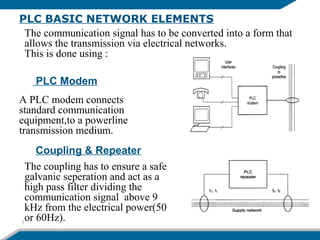
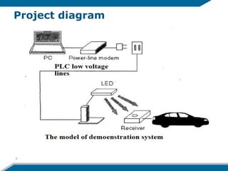
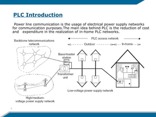
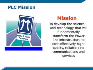
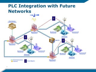
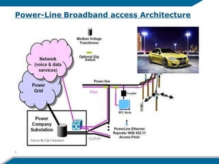
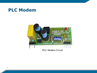
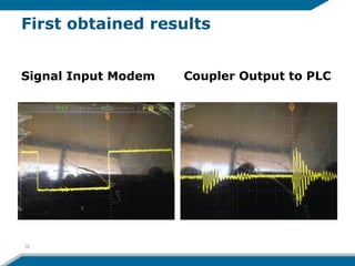
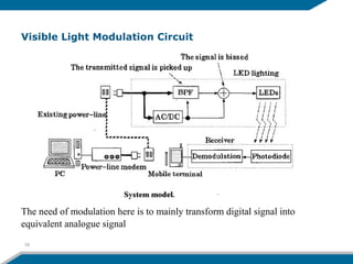
Using Street Lights for Transmitting, Broadcasting and Controlling
Communication Signals Over Low Voltage Network (PLC)
Diaa El Din Farouk
Department of Electrical and Electronic
Engineering Science
Power Line Communication
1
CONTENTS
PLC Introduction
PLC Integration with Future Networks
PLC Basic Network Elements
Project Objective & Diagram
Problem Definition & Challenges
Proposed Solution
Modulation Scheme
Obtained results
2
PLC Introduction
Power line communication is the usage of electrical power supply networks
for communication purposes.The main idea behind PLC is the reduction of cost
and expenditure in the realization of in-home PLC networks.
3
PLC Mission
Mission
To develop the science
and technology that will
fundamentally
transform the Power
line infrastructure to
cost-effectively high-
quality, reliable data
communications and
services
PLC Integration with Future
Networks
5
6
Power-Line Broadband access Architecture
PLC BASIC NETWORK ELEMENTS
7
The communication signal has to be converted into a form that
allows the transmission via electrical networks.
This is done using :
A PLC modem connects
standard communication
equipment,to a powerline
transmission medium.
PLC Modem
Coupling & Repeater
The coupling has to ensure a safe
galvanic seperation and act as a
high pass filter dividing the
communication signal above 9
kHz from the electrical power(50
or 60Hz).
Project Objectives
To propose an adequate design of complete
circuit connecting two different media for data
transmission
By Integrating White LED Visible-Light
Communication and Power-Line Communication
to be used to control or submit desired
information to moving cars in public streets.
8
Project diagram
9
The power line networks are not designed for
Data communication.
PLC has some impairments:
– High attenuation.
– Significant potential interference.
– Noise which is generated from all loads
connected to the grid.
Statement of The Problem
10
Challenges and Ongoing Work
– Total circuit implementation and
Integration
– Max distance to transfer the signal
between different light sources
– Low cost, high performance receiver
inside moving cars
– Using the system during day light
– Using appropriate frequency modulation
11
IMPORTANT ISSUES
Impedance, considerable noise, and high attenuation are the
main issues.
EMC( Electromagnetic Compatibility), due to which
transmission of data is limited to 2Mb/s to 4Mb/s.
Transmission of data rate at Low Voltage to many subcribers
also reduces the performance of data rate to moving cars.
12
Used Modulation Technique
Depending on the target application, each modulation
technique has certain advantages.
CDMA, FSK, OFDM are most known.
Spread Frequency Shift Keying (S-FSK) is a modulation
and demodulation technique which combines some of the
advantages of classical SS systems with the advantages
of a classical FSK system (low complexity, well
investigated implementations)
Coding Technique:
A transmission scheme combining M-ary FSK modulation
with diversity and coding can make transmission over
power lines robust against permanent frequency
disturbances and impulse noise.
13
Proposed Solution
14
PLC Modem
15
First obtained results
Signal Input Modem Coupler Output to PLC
16
Part II Visible Light circuit design
White LED offers advantageous properties
such as
– high brightness, cooler operation
– reliability,
– lower power consumption, lower voltage
– long lifetime
This system does not cause or suffer from
radio or electromagnetic interference
The function is based on the fast switching
of LEDs and the modulation of the visible-
light waves for free-space communications17
Visible Light Modulation Circuit
The need of modulation here is to mainly transform digital signal into
equivalent analogue signal
18
Visible Light Modulation Circuit
The XR 2206 is comprised of four
functional blocks; a voltage controlled
oscillator (VCO), an anloge multiplier
and sine shaper; a unity gain buffer
amplifier; and a set of current switches.
It offer output impedance in the range
600Ω +10%.
19
Visible Light Modulator circuit
20
The XR 2206 is comprised of four functional
blocks; a voltage controlled oscillator
(VCO), an analogue multiplier and sine
shaper
Applying efficient modulation scheme
for PLC environment , (SFSK) .
Optimize the physical & topological
design of PLC network by efficient
modes.
Applying encoding technique to
achieve high-data rates and reduce the
noise.
Design of a receiving circuit capable for
mobility usage.
Proposed Solutions Summary
21
22
Questions???
22

Power Line communication

  • 1.
    Using Street Lightsfor Transmitting, Broadcasting and Controlling Communication Signals Over Low Voltage Network (PLC) Diaa El Din Farouk Department of Electrical and Electronic Engineering Science Power Line Communication 1
  • 2.
    CONTENTS PLC Introduction PLC Integrationwith Future Networks PLC Basic Network Elements Project Objective & Diagram Problem Definition & Challenges Proposed Solution Modulation Scheme Obtained results 2
  • 3.
    PLC Introduction Power linecommunication is the usage of electrical power supply networks for communication purposes.The main idea behind PLC is the reduction of cost and expenditure in the realization of in-home PLC networks. 3
  • 4.
    PLC Mission Mission To developthe science and technology that will fundamentally transform the Power line infrastructure to cost-effectively high- quality, reliable data communications and services
  • 5.
    PLC Integration withFuture Networks 5
  • 6.
  • 7.
    PLC BASIC NETWORKELEMENTS 7 The communication signal has to be converted into a form that allows the transmission via electrical networks. This is done using : A PLC modem connects standard communication equipment,to a powerline transmission medium. PLC Modem Coupling & Repeater The coupling has to ensure a safe galvanic seperation and act as a high pass filter dividing the communication signal above 9 kHz from the electrical power(50 or 60Hz).
  • 8.
    Project Objectives To proposean adequate design of complete circuit connecting two different media for data transmission By Integrating White LED Visible-Light Communication and Power-Line Communication to be used to control or submit desired information to moving cars in public streets. 8
  • 9.
  • 10.
    The power linenetworks are not designed for Data communication. PLC has some impairments: – High attenuation. – Significant potential interference. – Noise which is generated from all loads connected to the grid. Statement of The Problem 10
  • 11.
    Challenges and OngoingWork – Total circuit implementation and Integration – Max distance to transfer the signal between different light sources – Low cost, high performance receiver inside moving cars – Using the system during day light – Using appropriate frequency modulation 11
  • 12.
    IMPORTANT ISSUES Impedance, considerablenoise, and high attenuation are the main issues. EMC( Electromagnetic Compatibility), due to which transmission of data is limited to 2Mb/s to 4Mb/s. Transmission of data rate at Low Voltage to many subcribers also reduces the performance of data rate to moving cars. 12
  • 13.
    Used Modulation Technique Dependingon the target application, each modulation technique has certain advantages. CDMA, FSK, OFDM are most known. Spread Frequency Shift Keying (S-FSK) is a modulation and demodulation technique which combines some of the advantages of classical SS systems with the advantages of a classical FSK system (low complexity, well investigated implementations) Coding Technique: A transmission scheme combining M-ary FSK modulation with diversity and coding can make transmission over power lines robust against permanent frequency disturbances and impulse noise. 13
  • 14.
  • 15.
  • 16.
    First obtained results SignalInput Modem Coupler Output to PLC 16
  • 17.
    Part II VisibleLight circuit design White LED offers advantageous properties such as – high brightness, cooler operation – reliability, – lower power consumption, lower voltage – long lifetime This system does not cause or suffer from radio or electromagnetic interference The function is based on the fast switching of LEDs and the modulation of the visible- light waves for free-space communications17
  • 18.
    Visible Light ModulationCircuit The need of modulation here is to mainly transform digital signal into equivalent analogue signal 18
  • 19.
    Visible Light ModulationCircuit The XR 2206 is comprised of four functional blocks; a voltage controlled oscillator (VCO), an anloge multiplier and sine shaper; a unity gain buffer amplifier; and a set of current switches. It offer output impedance in the range 600Ω +10%. 19
  • 20.
    Visible Light Modulatorcircuit 20 The XR 2206 is comprised of four functional blocks; a voltage controlled oscillator (VCO), an analogue multiplier and sine shaper
  • 21.
    Applying efficient modulationscheme for PLC environment , (SFSK) . Optimize the physical & topological design of PLC network by efficient modes. Applying encoding technique to achieve high-data rates and reduce the noise. Design of a receiving circuit capable for mobility usage. Proposed Solutions Summary 21
  • 22.