


![6. Sometimes, you may want to explode the block when you insert it. For example,
you might want to change the block. Of course, you can explode the block after
insertion, using the EXPLODE command, but the Insert dialog box gives you a
shortcut. Just check the Explode checkbox at the lower-left corner.
7. Click OK to close the dialog box and return to your drawing.
8.At the Specify insertion point or [Basepoint/Scale/Rotate]: prompt, specify
the insertion point for the block. The base point of the block (which you specified
when you created the block) will go at the insertion point. You can also use the
following options:
•Basepoint: Freezes the location of the block to let you temporarily change the
block’s basepoint. Keep the cursor in the drawing area as you do this, so you can
specify the new basepoint.
•Scale: Lets you specify a scale factor
•Rotate: Lets you specify a rotation angle.
32](https://image.slidesharecdn.com/autocadtariningreport-201011053003/85/AutoCAD-2D-training-report-32-320.jpg)
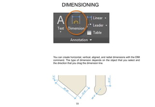


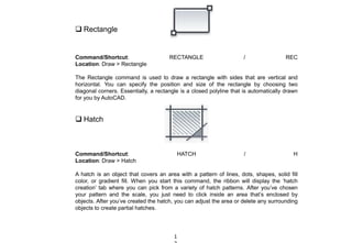
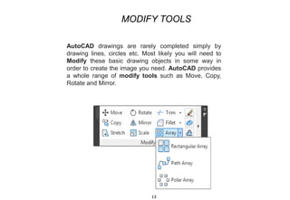
The document discusses AutoCAD, a computer-aided design and drafting software developed by Autodesk, first released in 1982. It details the software's features, history, applications across various industries, and its capabilities in creating 2D and 3D designs. AutoCAD is noted for its extensive editing tools, accuracy, and ability to manage geometric entities, making it essential for architects, engineers, and graphic designers.