SlideShare a Scribd company logo
1 of 32
SYSTEM DESIGN USING HDL (ECE43)
#
Digital system design using Verilog,
Charles Roth, Lizy Kurian John,
Byeong Kil Lee,
1st Edition, 2016, Cengage Learning
1 2.1, 2.2, 2.3 - 2.8, 2.11, 2.13 - 2.15
2 2.9, 2.10, 2.12, 2.16 - 2.19, 8.1, 8.2
3 3.1 - 3.4, 5.1, 5.2.1, 5.3
4 4.1 - 4.5, 4.8, 4.6, 4.7, 4.9, 4.11
5 6.1 - 6.5, 6.7 - 6.12
SIMULATION
AND SYNTHESIS
01/02/2019 2Aravinda K., Dept. of E&C, NHCE, Bengaluru
Delays in Verilog
Inertial delay Transport delay
Input pulse, that is
shorter than the delay
of the assignment, does
not get propagated to
the output.
propagation
delay of the gate
delay due to
the wire
Input pulse gets
transmitted to the
output, after the
assigned delay is
added to it’s value.
Net delay
updation of
the net’s value
When the net takes
the value from the
driver, the value on
the wire changes,
after a delay.
01/02/2019 3Aravinda K., Dept. of E&C, NHCE, Bengaluru
Delayed assignment
= transport delay
Delayed evaluation
= inertial delay
Illegal assignment
RHS of the statement
LHS of the statement
01/02/2019 4Aravinda K., Dept. of E&C, NHCE, Bengaluru
Net delay gets added to the RHS after
the inertial delay, because, the inertial
delay is from the driver of the net.
C1 rejects pulses that are less than 30 ns.
C2 rejects pulses that are less than 20 ns.
D rejects pulses that are less than 7 ns.
E rejects pulses that are less than 3 ns.
01/02/2019 5Aravinda K., Dept. of E&C, NHCE, Bengaluru
Compilation, simulation and synthesis
Compilation: Checking of syntax and semantic rules (e.g., presence of
semicolon, operation in between the signals of same type)
Elaboration: Instantiation of modules (e.g., creation of driver for each
signal, memory allocation for signals, interconnections among the ports)
Simulation: Initialization of values for the signals, and then, the
verification of the functionality of the modules
01/02/2019 6Aravinda K., Dept. of E&C, NHCE, Bengaluru
 A design consists of connected threads of execution, called as
processes.
 The processes include modules, assignment statements,
procedural blocks, system tasks etc.
 A change in a signal is referred to as an “event”, and Verilog uses
event-driven simulation.
 During simulation, each change in the value of a net or a
variable is called as “update event”.
 When an “update event” is executed, all the processes that are
sensitive to that event, are evaluated.
 As events occur at different times, they are kept on an “event
queue”, ordered by the “simulation time”.
 The processing of all active events is called a “simulation cycle”.
01/02/2019 7Aravinda K., Dept. of E&C, NHCE, Bengaluru
Name Contents of the region Example
Active event
region
events that occur in the current
simulation time (some events in this
region, will be moved to the other
regions, as per the event schedule)
continuous assignments
Inactive event
region
events that shall be processed after all
the active events are processed
blocking assignments
without delay
Non-blocking
assign update
region
events that are assigned to the current
simulation time, after all the active
and inactive events are processed
non-blocking
assignments without
delay
Monitor
event region
events that shall be processed after all
the active, inactive and non-blocking
assign update events are processed
$monitor, $strobe
Future event
region
events that occur at some future
simulation time
blocking as well as non-
blocking assignments
with delay
The Verilog event queue is segmented into five different regions
01/02/2019 8Aravinda K., Dept. of E&C, NHCE, Bengaluru
 Events are added to the
event queue in the source
code order.
 In this example, in the first
module, the variable “a” will
be assigned “0” after 5 ns,
and “1” after another 5 ns.
 In the second module, the
two “always” blocks are
concurrent, and hence there
is no ordering.
If a module contains more than
one process, all processes
execute concurrently.
01/02/2019 9Aravinda K., Dept. of E&C, NHCE, Bengaluru
 If “initial” block is not specified, the
variables would hold the value “x”.
 “always” statement waits until a signal
on the sensitivity list changes.
 During an event, when no time delay is
specified, Δ delay comes into picture.
 In this code, as the “x” value of ‘B’
changes to “0”, the first “always” gets
processed, and the value of ‘A’ changes
to “1” after the Δ delay.
 The second “always” also gets processed
at the same time, and the value of ‘B’
changes to “1” after 10 ns.
01/02/2019 10Aravinda K., Dept. of E&C, NHCE, Bengaluru
 For synthesis, it is not necessary
to perform simulation.
 The output of synthesis is the
“netlist”, which is a list of the
required components and their
interconnections.
 The netlist can be utilized to
implement the digital system,
by programming CPLD or FPGA.
01/02/2019 11Aravinda K., Dept. of E&C, NHCE, Bengaluru
Simple Synthesis Examples
Issues
1. The delay of 5 ns will not be present in
the hardware, as “#5” does not get
synthesized. If a delay has to be
modeled, then counter has to be
included in the code.
2. As ‘B’ is not present in the sensitivity
list, the synthesized hardware will not
produce any output whenever the
value of ‘B’ changes. Thus, simulated
output will be different from that of
the synthesizer.
Remedy
Check for synthesizer warnings of
missing signals in the sensitivity list.
Example - 1
Verilog code
Synthesized hardware
01/02/2019 12Aravinda K., Dept. of E&C, NHCE, Bengaluru
Example - 2Verilog code
Synthesized hardware
Block diagram
Internal circuitry
1. The values of ‘C’ and ‘G’ need to be
retained after the positive edge of
the clock. Therefore, flip-flops are
required for both ‘C’ and ‘G’.
2. A change in the value of ‘C’ from
statement-1 will not be considered
during the execution of statement-2.
01/02/2019 13Aravinda K., Dept. of E&C, NHCE, Bengaluru
Example - 3
If “clock” is omitted in the
sensitivity list of an “always”
statement, the synthesizer
may produce latches instead
of flip-flops. Hence, to reduce
the number of flip-flops, it is
better not to put the signal
assignments in a clocked
“always” statement.
Example - 4
The synthesizer will create
an empty blcok diagram, as
the output ‘D’ is not at all
assigned in the code. The
synthesizer will give the
following warnings:
01/02/2019 14Aravinda K., Dept. of E&C, NHCE, Bengaluru
01/02/2019 15Aravinda K., Dept. of E&C, NHCE, Bengaluru
Declaration of constants in Verilog
 There are three methods to define constant values: i) using the
compiler directive `define, ii) using the keyword parameter, iii) using
the keyword localparam.
Note: Constants defined using parameter can be changed during
module instantiation. For the constants which should not be changed,
localparam is used to define them.
i) `define constant_name constant_value
e.g., `define wordsize 16
reg [1: `wordsize] data;
Here, data is declared to be a reg of width wordsize.
ii) parameter constant_name = constant_value;
e.g., parameter msb = 15;
parameter [31:0] decim = 1’b1;
iii) localparam constant_name = constant_value;
e.g., localparameter pi = 3.1416;
01/02/2019 16Aravinda K., Dept. of E&C, NHCE, Bengaluru
Usage of arrays in Verilog
 Digital VLSI circuits consist of repeated use of similar structures,
and hence arrays can be utilized to model such structures, along with
the required array bounds.
Declaration
reg [0:7] regA; // an 8-bit register.
reg regB [0:7]; // an array of eight 1-bit registers.
wire wire_arrayA [5:0]; // an array of six wires.
integer intA [1:64]; // an array of sixty four integers.
reg [7:0] regC [15:0]; // an array of sixteen 8-bit registers.
Initialization
regA = 8’b10010110; // 8-bit register’s contents.
regC[15] = 8’b10100101; // 16th register’s 8-bit contents.
.
.
.
regC[0] = 8’b10010110; // 1st register’s 8-bit contents.
01/02/2019 17Aravinda K., Dept. of E&C, NHCE, Bengaluru
Matrices
 Matrices can be declared as multidimensional arrays. A matrix of
size (4X3) with 8-bit elements is declared and initialized as follows –
reg [7:0] matrixA [0:3][0:2] = {{4, 2, 9},
{1, 3, 4},
{8, 6, 7},
{5, 9, 2}};
 The array element referenced as matrixA[2][1] implies the element
that is in 3rd row and 2nd column, and it contains the value 6.
 The arrays, along with the parameters, can be used to construct
look-up tables (LUT), which can be used to create combinational
circuits using ROM or LUT.
01/02/2019 18Aravinda K., Dept. of E&C, NHCE, Bengaluru
Input
(LUT Address)
Output
(LUT Data)
0000 00001
0001 00010
0010 00100
0011 00111
0100 01000
0101 01011
0110 01101
0111 01110
1000 10000
1001 10011
1010 10101
1011 10110
1100 11001
1101 11010
1110 11100
1111 11111
Example: odd parity representation for 4-bit numbers
Verilog code for the example
module parity_gen(X,Y);
input [3:0] X;
output [4:0] Y;
wire paritybit;
parameter [0:15] onebit = {1’b1, 1’b0, 1’b0, 1’b1,
1’b0, 1’b1, 1’b1, 1’b0, 1’b0, 1’b1, 1’b1, 1’b0, 1’b1,
1’b0, 1’b0, 1’b1};
assign paritybit = onebit[X];
assign Y = {X, paritybit};
Endmodule
 As the first 4 bits of the output are
identical to the input, it is not necessary to
store all the 5-bit 16 numbers in the LUT.
 Therefore, only the 16 parity bits can be
stored, and the particular parity bit can be
concatenated with the respective input bit.
01/02/2019 19Aravinda K., Dept. of E&C, NHCE, Bengaluru
Usage of loops in Verilog
 A system, in which an activity is happening in a repetitive fashion,
can be represented by means of a loop.
 The loop statements are sequential in nature. In Verilog, the keywords
“forever”, “for”, “while” and “repeat” are used for the same.
 There can be an infinite loop, as follows:
begin
clk = 1’b0;
forever #10 clk = ~clk;
end
01/02/2019 20Aravinda K., Dept. of E&C, NHCE, Bengaluru
01/02/2019 21Aravinda K., Dept. of E&C, NHCE, Bengaluru
Testing a Verilog Model
 A test bench is a separate Verilog code, which provides input
combinations, to test a Verilog model.
 In other words, the test bench is used during simulation, to provide
stimuli to the system or circuit under test.
 The test bench module does not have external inputs and outputs, and
hence the port list in the module declaration, will be empty.
Example: 4-bit adder
An exhaustive test of this adder
requires 512 tests (16 numbers of
Addend X 16 numbers of Augend
X 2 values of Carry-in).
Design Under Test
Test bench (Top module)
01/02/2019 22Aravinda K., Dept. of E&C, NHCE, Bengaluru
Test bench program with a random set of 11 tests
01/02/2019 23Aravinda K., Dept. of E&C, NHCE, Bengaluru
01/02/2019 Aravinda K., Dept. of E&C, NHCE, Bengaluru 24
Verilog Functions
 A function returns only a single value, and a function cannot contain delays.
 Functions and tasks can be defined in the module that they will be used in.
 A function call in the program file can happen just like an expression.
 A function can call other functions, but the function cannot call tasks.
 If a function or a task is defined as a separate file, then the compiler
directive `include has to be used in the program file.
Example-1: Write a function for generating an even parity bit for a 4-bit number.
function [4:0] even_parity;
input [3:0] A;
reg temp;
begin
temp = A[0]^A[1]^A[2]^A[3];
even_parity = {A, temp};
end
endfunction
module even_test(Z);
output reg [4:0] Z;
reg [3:0] INP;
initial
begin
INP = 4’b0101;
Z = even_parity(INP);
end
endmodule
01/02/2019 Aravinda K., Dept. of E&C, NHCE, Bengaluru 25
Example-2:
Write a function
to add two
4-bit numbers
function [4:0] add4;
input [3:0] A,B;
input cin;
reg [4:0] sum;
reg cout;
begin
integer i;
for (i=0; i<=3; i=i+1)
begin
cout = (A[i] & B[i]) | (B[i] & cin) | (A[i] & cin);
sum[i] = A[i] ^ B[i] ^ cin;
cin = cout;
end
sum[4] = cout;
add4 = sum;
end
endfunction
Function call: i) Z <= add4(X, Y, 0); // for adding Y to Z
ii) Z <= add4(X, ~Y, 1); // for subtracting Y from Z, ignoring Z[4]
01/02/2019 Aravinda K., Dept. of E&C, NHCE, Bengaluru 26
Example-3:
Write a program which
computes the square of a 4-bit
number, by using a function
module squares_test (clk);
input clk;
reg [3:0] temp;
reg [7:0] answer;
function [7:0] squares;
input [3:0] number;
begin
squares = number * number;
end
endfunction
initial
begin
temp = 4’b0011;
end
always @(posedge clk)
begin
answer = squares (temp)
end
endmodule
 A function must have at least
one input argument.
 The function cannot have output
or inout arguments.
 Recursive functions must be
declared as automatic.
01/02/2019 Aravinda K., Dept. of E&C, NHCE, Bengaluru 27
Verilog Tasks
 Unlike functions, the tasks can return any number of values.
 Tasks can contain delay, event and timing control statements.
 Tasks can have arguments of type input, output and inout.
This task adds two 4-bit numbers.
Task call:
01/02/2019 Aravinda K., Dept. of E&C, NHCE, Bengaluru 28
Function Task
At least one input argument,
but no output or inout
arguments
Any number of input, output or
inout arguments
Returns a single value by
assigning the value to the
function name
Passes multiple values that are
declared inside
Can call other functions, but
cannot call tasks
Can call other functions or tasks
Cannot contain any time-
controlled statements
Can contain time-controlled
statements
Executes in zero simulation time
Executes in non-zero simulation
time
01/02/2019 29Aravinda K., Dept. of E&C, NHCE, Bengaluru
Name Function
$display Prints the test’s results on the screen, exactly after
execution, and then adds a newline character
$write Prints the test’s results on the screen, exactly after
execution, but does not add a newline character
$strobe Prints the test’s results on the screen, at the end of
the current simulation time
$monitor Prints the test’s results on the screen, every time
when one of its parameters changes
System tasks to observe the outputs
01/02/2019 30Aravinda K., Dept. of E&C, NHCE, Bengaluru
System tasks to observe the outputs
$display(“Simulation time is %t”, $time);
Simulation time is 10
Simulation time is 11
$write(“Simulation time is %t”, $time);
Simulation time is 10 Simulation
time is 11
01/02/2019 31Aravinda K., Dept. of E&C, NHCE, Bengaluru
always@(posedge reset)
$strobe(“The FlipFlop value is %b at time %t”, q, $time);
The FlipFlop value is 1 at time 17
The FlipFlop value is 0 at time 24
The FlipFlop value is 1 at time 26
initial
$monitor(“At %t, d=%d, clk=%d”, $time, d, clk, “and q is %b”, q);
At 24, d=x, clk=x and q is 0
At 25, d=x, clk=x and q is 1
At 30, d=0, clk=x and q is 1
At 35, d=0, clk=1 and q is 1
At 40, d=0, clk=0 and q is 1
01/02/2019 32Aravinda K., Dept. of E&C, NHCE, Bengaluru

More Related Content

What's hot

Vhdl code and project report of arithmetic and logic unit
Vhdl code and project report of arithmetic and logic unitVhdl code and project report of arithmetic and logic unit
Vhdl code and project report of arithmetic and logic unitNikhil Sahu
 
VHDL Packages, Coding Styles for Arithmetic Operations and VHDL-200x Additions
VHDL Packages, Coding Styles for Arithmetic Operations and VHDL-200x AdditionsVHDL Packages, Coding Styles for Arithmetic Operations and VHDL-200x Additions
VHDL Packages, Coding Styles for Arithmetic Operations and VHDL-200x AdditionsAmal Khailtash
 
Verilog presentation final
Verilog presentation finalVerilog presentation final
Verilog presentation finalAnkur Gupta
 
Ieee project reversible logic gates by_amit
Ieee project reversible logic gates  by_amitIeee project reversible logic gates  by_amit
Ieee project reversible logic gates by_amitAmith Bhonsle
 
INTRODUCTION TO VHDL
INTRODUCTION    TO    VHDLINTRODUCTION    TO    VHDL
INTRODUCTION TO VHDLkarthikpunuru
 
Introduction to VHDL
Introduction to VHDLIntroduction to VHDL
Introduction to VHDLYaser Kalifa
 
Fpga 06-data-types-system-tasks-compiler-directives
Fpga 06-data-types-system-tasks-compiler-directivesFpga 06-data-types-system-tasks-compiler-directives
Fpga 06-data-types-system-tasks-compiler-directivesMalik Tauqir Hasan
 
Experiences from Designing and Validating a Software Modernization Transforma...
Experiences from Designing and Validating a Software Modernization Transforma...Experiences from Designing and Validating a Software Modernization Transforma...
Experiences from Designing and Validating a Software Modernization Transforma...Alexandru-Florin Iosif-Lazăr
 
An Introductory course on Verilog HDL-Verilog hdl ppr
An Introductory course on Verilog HDL-Verilog hdl pprAn Introductory course on Verilog HDL-Verilog hdl ppr
An Introductory course on Verilog HDL-Verilog hdl pprPrabhavathi P
 
IRJET- Data Analysis for Braking System in Time Domain for Fault Diagnosis
IRJET- Data Analysis for Braking System in Time Domain for Fault DiagnosisIRJET- Data Analysis for Braking System in Time Domain for Fault Diagnosis
IRJET- Data Analysis for Braking System in Time Domain for Fault DiagnosisIRJET Journal
 
VHdl lab report
VHdl lab reportVHdl lab report
VHdl lab reportJinesh Kb
 
Verilog 語法教學
Verilog 語法教學 Verilog 語法教學
Verilog 語法教學 艾鍗科技
 
FPGA training session generic package and funtions of VHDL by Digitronix Nepal
FPGA training session generic package and funtions of VHDL by Digitronix NepalFPGA training session generic package and funtions of VHDL by Digitronix Nepal
FPGA training session generic package and funtions of VHDL by Digitronix NepalKrishna Gaihre
 

What's hot (20)

VHDL CODE
VHDL CODE VHDL CODE
VHDL CODE
 
Vhdl
VhdlVhdl
Vhdl
 
Vhdl code and project report of arithmetic and logic unit
Vhdl code and project report of arithmetic and logic unitVhdl code and project report of arithmetic and logic unit
Vhdl code and project report of arithmetic and logic unit
 
VHDL Packages, Coding Styles for Arithmetic Operations and VHDL-200x Additions
VHDL Packages, Coding Styles for Arithmetic Operations and VHDL-200x AdditionsVHDL Packages, Coding Styles for Arithmetic Operations and VHDL-200x Additions
VHDL Packages, Coding Styles for Arithmetic Operations and VHDL-200x Additions
 
Verilogspk1
Verilogspk1Verilogspk1
Verilogspk1
 
Verilog presentation final
Verilog presentation finalVerilog presentation final
Verilog presentation final
 
Ieee project reversible logic gates by_amit
Ieee project reversible logic gates  by_amitIeee project reversible logic gates  by_amit
Ieee project reversible logic gates by_amit
 
INTRODUCTION TO VHDL
INTRODUCTION    TO    VHDLINTRODUCTION    TO    VHDL
INTRODUCTION TO VHDL
 
Coding verilog
Coding verilogCoding verilog
Coding verilog
 
VHDL
VHDLVHDL
VHDL
 
Programs of VHDL
Programs of VHDLPrograms of VHDL
Programs of VHDL
 
Introduction to VHDL
Introduction to VHDLIntroduction to VHDL
Introduction to VHDL
 
Fpga 06-data-types-system-tasks-compiler-directives
Fpga 06-data-types-system-tasks-compiler-directivesFpga 06-data-types-system-tasks-compiler-directives
Fpga 06-data-types-system-tasks-compiler-directives
 
Experiences from Designing and Validating a Software Modernization Transforma...
Experiences from Designing and Validating a Software Modernization Transforma...Experiences from Designing and Validating a Software Modernization Transforma...
Experiences from Designing and Validating a Software Modernization Transforma...
 
An Introductory course on Verilog HDL-Verilog hdl ppr
An Introductory course on Verilog HDL-Verilog hdl pprAn Introductory course on Verilog HDL-Verilog hdl ppr
An Introductory course on Verilog HDL-Verilog hdl ppr
 
Vhdl programming
Vhdl programmingVhdl programming
Vhdl programming
 
IRJET- Data Analysis for Braking System in Time Domain for Fault Diagnosis
IRJET- Data Analysis for Braking System in Time Domain for Fault DiagnosisIRJET- Data Analysis for Braking System in Time Domain for Fault Diagnosis
IRJET- Data Analysis for Braking System in Time Domain for Fault Diagnosis
 
VHdl lab report
VHdl lab reportVHdl lab report
VHdl lab report
 
Verilog 語法教學
Verilog 語法教學 Verilog 語法教學
Verilog 語法教學
 
FPGA training session generic package and funtions of VHDL by Digitronix Nepal
FPGA training session generic package and funtions of VHDL by Digitronix NepalFPGA training session generic package and funtions of VHDL by Digitronix Nepal
FPGA training session generic package and funtions of VHDL by Digitronix Nepal
 

Similar to System design using HDL - Module 2

Optimizing Data Encoding Technique For Dynamic Power Reduction In Network On ...
Optimizing Data Encoding Technique For Dynamic Power Reduction In Network On ...Optimizing Data Encoding Technique For Dynamic Power Reduction In Network On ...
Optimizing Data Encoding Technique For Dynamic Power Reduction In Network On ...IRJET Journal
 
A Novel Efficient VLSI Architecture for IEEE 754 Floating point multiplier us...
A Novel Efficient VLSI Architecture for IEEE 754 Floating point multiplier us...A Novel Efficient VLSI Architecture for IEEE 754 Floating point multiplier us...
A Novel Efficient VLSI Architecture for IEEE 754 Floating point multiplier us...IJERA Editor
 
Implementation of an Effective Self-Timed Multiplier for Single Precision Flo...
Implementation of an Effective Self-Timed Multiplier for Single Precision Flo...Implementation of an Effective Self-Timed Multiplier for Single Precision Flo...
Implementation of an Effective Self-Timed Multiplier for Single Precision Flo...IRJET Journal
 
International Journal of Computational Engineering Research (IJCER)
International Journal of Computational Engineering Research (IJCER) International Journal of Computational Engineering Research (IJCER)
International Journal of Computational Engineering Research (IJCER) ijceronline
 
Fpga 07-port-rules-gate-delay-data-flow-carry-look-ahead-adder
Fpga 07-port-rules-gate-delay-data-flow-carry-look-ahead-adderFpga 07-port-rules-gate-delay-data-flow-carry-look-ahead-adder
Fpga 07-port-rules-gate-delay-data-flow-carry-look-ahead-adderMalik Tauqir Hasan
 
IRJET- FPGA Implementation of High Speed and Low Power Speculative Adder
IRJET-  	  FPGA Implementation of  High Speed and Low Power Speculative AdderIRJET-  	  FPGA Implementation of  High Speed and Low Power Speculative Adder
IRJET- FPGA Implementation of High Speed and Low Power Speculative AdderIRJET Journal
 
Design and implementation of synchronous 4 bit up counter using 180 nm cmos p...
Design and implementation of synchronous 4 bit up counter using 180 nm cmos p...Design and implementation of synchronous 4 bit up counter using 180 nm cmos p...
Design and implementation of synchronous 4 bit up counter using 180 nm cmos p...eSAT Publishing House
 
IRJET- Single Precision Floating Point Arithmetic using VHDL Coding
IRJET-  	  Single Precision Floating Point Arithmetic using VHDL CodingIRJET-  	  Single Precision Floating Point Arithmetic using VHDL Coding
IRJET- Single Precision Floating Point Arithmetic using VHDL CodingIRJET Journal
 
IRJET- Performance Estimation of FIR Filter using Null Convention Logic
IRJET-  	  Performance Estimation of FIR Filter using Null Convention LogicIRJET-  	  Performance Estimation of FIR Filter using Null Convention Logic
IRJET- Performance Estimation of FIR Filter using Null Convention LogicIRJET Journal
 
Implementation of 32 Bit Binary Floating Point Adder Using IEEE 754 Single Pr...
Implementation of 32 Bit Binary Floating Point Adder Using IEEE 754 Single Pr...Implementation of 32 Bit Binary Floating Point Adder Using IEEE 754 Single Pr...
Implementation of 32 Bit Binary Floating Point Adder Using IEEE 754 Single Pr...iosrjce
 
SKEL 4273 CAD with HDL Topic 2
SKEL 4273 CAD with HDL Topic 2SKEL 4273 CAD with HDL Topic 2
SKEL 4273 CAD with HDL Topic 2alhadi81
 
Implementation of Designed Encoder and Decoder for Golay Code
Implementation of Designed Encoder and Decoder for Golay CodeImplementation of Designed Encoder and Decoder for Golay Code
Implementation of Designed Encoder and Decoder for Golay CodeIRJET Journal
 
IRJET- FPGA Implementation of Orthogonal Codes for Efficient Digital Communic...
IRJET- FPGA Implementation of Orthogonal Codes for Efficient Digital Communic...IRJET- FPGA Implementation of Orthogonal Codes for Efficient Digital Communic...
IRJET- FPGA Implementation of Orthogonal Codes for Efficient Digital Communic...IRJET Journal
 
Design and Implementation of Single Precision Pipelined Floating Point Co-Pro...
Design and Implementation of Single Precision Pipelined Floating Point Co-Pro...Design and Implementation of Single Precision Pipelined Floating Point Co-Pro...
Design and Implementation of Single Precision Pipelined Floating Point Co-Pro...Silicon Mentor
 
An approach to Measure Transition Density of Binary Sequences for X-filling b...
An approach to Measure Transition Density of Binary Sequences for X-filling b...An approach to Measure Transition Density of Binary Sequences for X-filling b...
An approach to Measure Transition Density of Binary Sequences for X-filling b...IJECEIAES
 
IRJET - Handwritten Bangla Digit Recognition using Capsule Network
IRJET -  	  Handwritten Bangla Digit Recognition using Capsule NetworkIRJET -  	  Handwritten Bangla Digit Recognition using Capsule Network
IRJET - Handwritten Bangla Digit Recognition using Capsule NetworkIRJET Journal
 
7 Elements Of Verilog HDL
7 Elements Of Verilog HDL7 Elements Of Verilog HDL
7 Elements Of Verilog HDLAllison Koehn
 
IRJET- To Design 16 bit Synchronous Microprocessor using VHDL on FPGA
IRJET-  	  To Design 16 bit Synchronous Microprocessor using VHDL on FPGAIRJET-  	  To Design 16 bit Synchronous Microprocessor using VHDL on FPGA
IRJET- To Design 16 bit Synchronous Microprocessor using VHDL on FPGAIRJET Journal
 
IRJET- Review Paper on Study of Various Interleavers and their Significance
IRJET- Review Paper on Study of Various Interleavers and their SignificanceIRJET- Review Paper on Study of Various Interleavers and their Significance
IRJET- Review Paper on Study of Various Interleavers and their SignificanceIRJET Journal
 
Iaetsd implementation of power efficient iterative logarithmic multiplier usi...
Iaetsd implementation of power efficient iterative logarithmic multiplier usi...Iaetsd implementation of power efficient iterative logarithmic multiplier usi...
Iaetsd implementation of power efficient iterative logarithmic multiplier usi...Iaetsd Iaetsd
 

Similar to System design using HDL - Module 2 (20)

Optimizing Data Encoding Technique For Dynamic Power Reduction In Network On ...
Optimizing Data Encoding Technique For Dynamic Power Reduction In Network On ...Optimizing Data Encoding Technique For Dynamic Power Reduction In Network On ...
Optimizing Data Encoding Technique For Dynamic Power Reduction In Network On ...
 
A Novel Efficient VLSI Architecture for IEEE 754 Floating point multiplier us...
A Novel Efficient VLSI Architecture for IEEE 754 Floating point multiplier us...A Novel Efficient VLSI Architecture for IEEE 754 Floating point multiplier us...
A Novel Efficient VLSI Architecture for IEEE 754 Floating point multiplier us...
 
Implementation of an Effective Self-Timed Multiplier for Single Precision Flo...
Implementation of an Effective Self-Timed Multiplier for Single Precision Flo...Implementation of an Effective Self-Timed Multiplier for Single Precision Flo...
Implementation of an Effective Self-Timed Multiplier for Single Precision Flo...
 
International Journal of Computational Engineering Research (IJCER)
International Journal of Computational Engineering Research (IJCER) International Journal of Computational Engineering Research (IJCER)
International Journal of Computational Engineering Research (IJCER)
 
Fpga 07-port-rules-gate-delay-data-flow-carry-look-ahead-adder
Fpga 07-port-rules-gate-delay-data-flow-carry-look-ahead-adderFpga 07-port-rules-gate-delay-data-flow-carry-look-ahead-adder
Fpga 07-port-rules-gate-delay-data-flow-carry-look-ahead-adder
 
IRJET- FPGA Implementation of High Speed and Low Power Speculative Adder
IRJET-  	  FPGA Implementation of  High Speed and Low Power Speculative AdderIRJET-  	  FPGA Implementation of  High Speed and Low Power Speculative Adder
IRJET- FPGA Implementation of High Speed and Low Power Speculative Adder
 
Design and implementation of synchronous 4 bit up counter using 180 nm cmos p...
Design and implementation of synchronous 4 bit up counter using 180 nm cmos p...Design and implementation of synchronous 4 bit up counter using 180 nm cmos p...
Design and implementation of synchronous 4 bit up counter using 180 nm cmos p...
 
IRJET- Single Precision Floating Point Arithmetic using VHDL Coding
IRJET-  	  Single Precision Floating Point Arithmetic using VHDL CodingIRJET-  	  Single Precision Floating Point Arithmetic using VHDL Coding
IRJET- Single Precision Floating Point Arithmetic using VHDL Coding
 
IRJET- Performance Estimation of FIR Filter using Null Convention Logic
IRJET-  	  Performance Estimation of FIR Filter using Null Convention LogicIRJET-  	  Performance Estimation of FIR Filter using Null Convention Logic
IRJET- Performance Estimation of FIR Filter using Null Convention Logic
 
Implementation of 32 Bit Binary Floating Point Adder Using IEEE 754 Single Pr...
Implementation of 32 Bit Binary Floating Point Adder Using IEEE 754 Single Pr...Implementation of 32 Bit Binary Floating Point Adder Using IEEE 754 Single Pr...
Implementation of 32 Bit Binary Floating Point Adder Using IEEE 754 Single Pr...
 
SKEL 4273 CAD with HDL Topic 2
SKEL 4273 CAD with HDL Topic 2SKEL 4273 CAD with HDL Topic 2
SKEL 4273 CAD with HDL Topic 2
 
Implementation of Designed Encoder and Decoder for Golay Code
Implementation of Designed Encoder and Decoder for Golay CodeImplementation of Designed Encoder and Decoder for Golay Code
Implementation of Designed Encoder and Decoder for Golay Code
 
IRJET- FPGA Implementation of Orthogonal Codes for Efficient Digital Communic...
IRJET- FPGA Implementation of Orthogonal Codes for Efficient Digital Communic...IRJET- FPGA Implementation of Orthogonal Codes for Efficient Digital Communic...
IRJET- FPGA Implementation of Orthogonal Codes for Efficient Digital Communic...
 
Design and Implementation of Single Precision Pipelined Floating Point Co-Pro...
Design and Implementation of Single Precision Pipelined Floating Point Co-Pro...Design and Implementation of Single Precision Pipelined Floating Point Co-Pro...
Design and Implementation of Single Precision Pipelined Floating Point Co-Pro...
 
An approach to Measure Transition Density of Binary Sequences for X-filling b...
An approach to Measure Transition Density of Binary Sequences for X-filling b...An approach to Measure Transition Density of Binary Sequences for X-filling b...
An approach to Measure Transition Density of Binary Sequences for X-filling b...
 
IRJET - Handwritten Bangla Digit Recognition using Capsule Network
IRJET -  	  Handwritten Bangla Digit Recognition using Capsule NetworkIRJET -  	  Handwritten Bangla Digit Recognition using Capsule Network
IRJET - Handwritten Bangla Digit Recognition using Capsule Network
 
7 Elements Of Verilog HDL
7 Elements Of Verilog HDL7 Elements Of Verilog HDL
7 Elements Of Verilog HDL
 
IRJET- To Design 16 bit Synchronous Microprocessor using VHDL on FPGA
IRJET-  	  To Design 16 bit Synchronous Microprocessor using VHDL on FPGAIRJET-  	  To Design 16 bit Synchronous Microprocessor using VHDL on FPGA
IRJET- To Design 16 bit Synchronous Microprocessor using VHDL on FPGA
 
IRJET- Review Paper on Study of Various Interleavers and their Significance
IRJET- Review Paper on Study of Various Interleavers and their SignificanceIRJET- Review Paper on Study of Various Interleavers and their Significance
IRJET- Review Paper on Study of Various Interleavers and their Significance
 
Iaetsd implementation of power efficient iterative logarithmic multiplier usi...
Iaetsd implementation of power efficient iterative logarithmic multiplier usi...Iaetsd implementation of power efficient iterative logarithmic multiplier usi...
Iaetsd implementation of power efficient iterative logarithmic multiplier usi...
 

More from Aravinda Koithyar

More from Aravinda Koithyar (20)

Analog Electronic Circuits - Module 5
Analog Electronic Circuits - Module 5Analog Electronic Circuits - Module 5
Analog Electronic Circuits - Module 5
 
Analog Electronic Circuits - Module 4
Analog Electronic Circuits - Module 4Analog Electronic Circuits - Module 4
Analog Electronic Circuits - Module 4
 
Analog Electronic Circuits - Module 3
Analog Electronic Circuits - Module 3Analog Electronic Circuits - Module 3
Analog Electronic Circuits - Module 3
 
Analog Electronic Circuits - Module 2.3
Analog Electronic Circuits - Module 2.3Analog Electronic Circuits - Module 2.3
Analog Electronic Circuits - Module 2.3
 
Analog Electronic Circuits - Module 2.2
Analog Electronic Circuits - Module 2.2Analog Electronic Circuits - Module 2.2
Analog Electronic Circuits - Module 2.2
 
Analog Electronic Circuits - Module 2.1
Analog Electronic Circuits - Module 2.1Analog Electronic Circuits - Module 2.1
Analog Electronic Circuits - Module 2.1
 
System design using HDL - Module 1
System design using HDL - Module 1System design using HDL - Module 1
System design using HDL - Module 1
 
System design using HDL - Module 5
System design using HDL - Module 5System design using HDL - Module 5
System design using HDL - Module 5
 
System design using HDL - Module 3
System design using HDL - Module 3System design using HDL - Module 3
System design using HDL - Module 3
 
Spiritual health through yoga
Spiritual health through yogaSpiritual health through yoga
Spiritual health through yoga
 
Lessons of leadership
Lessons of leadershipLessons of leadership
Lessons of leadership
 
Great sayings
Great sayingsGreat sayings
Great sayings
 
Sanskrit words with pictures
Sanskrit words with picturesSanskrit words with pictures
Sanskrit words with pictures
 
Guru and Gaayathree
Guru and GaayathreeGuru and Gaayathree
Guru and Gaayathree
 
Samskrtha Pravesha
Samskrtha PraveshaSamskrtha Pravesha
Samskrtha Pravesha
 
Adi shankara's literary works
Adi shankara's literary worksAdi shankara's literary works
Adi shankara's literary works
 
Introduction to yoga
Introduction to yogaIntroduction to yoga
Introduction to yoga
 
Pranayama
PranayamaPranayama
Pranayama
 
Sacred secret
Sacred secretSacred secret
Sacred secret
 
Memory
MemoryMemory
Memory
 

Recently uploaded

Biology for Computer Engineers Course Handout.pptx
Biology for Computer Engineers Course Handout.pptxBiology for Computer Engineers Course Handout.pptx
Biology for Computer Engineers Course Handout.pptxDeepakSakkari2
 
Software and Systems Engineering Standards: Verification and Validation of Sy...
Software and Systems Engineering Standards: Verification and Validation of Sy...Software and Systems Engineering Standards: Verification and Validation of Sy...
Software and Systems Engineering Standards: Verification and Validation of Sy...VICTOR MAESTRE RAMIREZ
 
main PPT.pptx of girls hostel security using rfid
main PPT.pptx of girls hostel security using rfidmain PPT.pptx of girls hostel security using rfid
main PPT.pptx of girls hostel security using rfidNikhilNagaraju
 
chaitra-1.pptx fake news detection using machine learning
chaitra-1.pptx  fake news detection using machine learningchaitra-1.pptx  fake news detection using machine learning
chaitra-1.pptx fake news detection using machine learningmisbanausheenparvam
 
Introduction to Microprocesso programming and interfacing.pptx
Introduction to Microprocesso programming and interfacing.pptxIntroduction to Microprocesso programming and interfacing.pptx
Introduction to Microprocesso programming and interfacing.pptxvipinkmenon1
 
Call Girls Narol 7397865700 Independent Call Girls
Call Girls Narol 7397865700 Independent Call GirlsCall Girls Narol 7397865700 Independent Call Girls
Call Girls Narol 7397865700 Independent Call Girlsssuser7cb4ff
 
Past, Present and Future of Generative AI
Past, Present and Future of Generative AIPast, Present and Future of Generative AI
Past, Present and Future of Generative AIabhishek36461
 
Study on Air-Water & Water-Water Heat Exchange in a Finned Tube Exchanger
Study on Air-Water & Water-Water Heat Exchange in a Finned Tube ExchangerStudy on Air-Water & Water-Water Heat Exchange in a Finned Tube Exchanger
Study on Air-Water & Water-Water Heat Exchange in a Finned Tube ExchangerAnamika Sarkar
 
Churning of Butter, Factors affecting .
Churning of Butter, Factors affecting  .Churning of Butter, Factors affecting  .
Churning of Butter, Factors affecting .Satyam Kumar
 
INFLUENCE OF NANOSILICA ON THE PROPERTIES OF CONCRETE
INFLUENCE OF NANOSILICA ON THE PROPERTIES OF CONCRETEINFLUENCE OF NANOSILICA ON THE PROPERTIES OF CONCRETE
INFLUENCE OF NANOSILICA ON THE PROPERTIES OF CONCRETEroselinkalist12
 
IVE Industry Focused Event - Defence Sector 2024
IVE Industry Focused Event - Defence Sector 2024IVE Industry Focused Event - Defence Sector 2024
IVE Industry Focused Event - Defence Sector 2024Mark Billinghurst
 
Architect Hassan Khalil Portfolio for 2024
Architect Hassan Khalil Portfolio for 2024Architect Hassan Khalil Portfolio for 2024
Architect Hassan Khalil Portfolio for 2024hassan khalil
 
CCS355 Neural Network & Deep Learning Unit II Notes with Question bank .pdf
CCS355 Neural Network & Deep Learning Unit II Notes with Question bank .pdfCCS355 Neural Network & Deep Learning Unit II Notes with Question bank .pdf
CCS355 Neural Network & Deep Learning Unit II Notes with Question bank .pdfAsst.prof M.Gokilavani
 
Concrete Mix Design - IS 10262-2019 - .pptx
Concrete Mix Design - IS 10262-2019 - .pptxConcrete Mix Design - IS 10262-2019 - .pptx
Concrete Mix Design - IS 10262-2019 - .pptxKartikeyaDwivedi3
 
power system scada applications and uses
power system scada applications and usespower system scada applications and uses
power system scada applications and usesDevarapalliHaritha
 
Electronically Controlled suspensions system .pdf
Electronically Controlled suspensions system .pdfElectronically Controlled suspensions system .pdf
Electronically Controlled suspensions system .pdfme23b1001
 
Oxy acetylene welding presentation note.
Oxy acetylene welding presentation note.Oxy acetylene welding presentation note.
Oxy acetylene welding presentation note.eptoze12
 
Decoding Kotlin - Your guide to solving the mysterious in Kotlin.pptx
Decoding Kotlin - Your guide to solving the mysterious in Kotlin.pptxDecoding Kotlin - Your guide to solving the mysterious in Kotlin.pptx
Decoding Kotlin - Your guide to solving the mysterious in Kotlin.pptxJoão Esperancinha
 

Recently uploaded (20)

Biology for Computer Engineers Course Handout.pptx
Biology for Computer Engineers Course Handout.pptxBiology for Computer Engineers Course Handout.pptx
Biology for Computer Engineers Course Handout.pptx
 
Software and Systems Engineering Standards: Verification and Validation of Sy...
Software and Systems Engineering Standards: Verification and Validation of Sy...Software and Systems Engineering Standards: Verification and Validation of Sy...
Software and Systems Engineering Standards: Verification and Validation of Sy...
 
main PPT.pptx of girls hostel security using rfid
main PPT.pptx of girls hostel security using rfidmain PPT.pptx of girls hostel security using rfid
main PPT.pptx of girls hostel security using rfid
 
chaitra-1.pptx fake news detection using machine learning
chaitra-1.pptx  fake news detection using machine learningchaitra-1.pptx  fake news detection using machine learning
chaitra-1.pptx fake news detection using machine learning
 
Introduction to Microprocesso programming and interfacing.pptx
Introduction to Microprocesso programming and interfacing.pptxIntroduction to Microprocesso programming and interfacing.pptx
Introduction to Microprocesso programming and interfacing.pptx
 
young call girls in Rajiv Chowk🔝 9953056974 🔝 Delhi escort Service
young call girls in Rajiv Chowk🔝 9953056974 🔝 Delhi escort Serviceyoung call girls in Rajiv Chowk🔝 9953056974 🔝 Delhi escort Service
young call girls in Rajiv Chowk🔝 9953056974 🔝 Delhi escort Service
 
Call Girls Narol 7397865700 Independent Call Girls
Call Girls Narol 7397865700 Independent Call GirlsCall Girls Narol 7397865700 Independent Call Girls
Call Girls Narol 7397865700 Independent Call Girls
 
Past, Present and Future of Generative AI
Past, Present and Future of Generative AIPast, Present and Future of Generative AI
Past, Present and Future of Generative AI
 
Study on Air-Water & Water-Water Heat Exchange in a Finned Tube Exchanger
Study on Air-Water & Water-Water Heat Exchange in a Finned Tube ExchangerStudy on Air-Water & Water-Water Heat Exchange in a Finned Tube Exchanger
Study on Air-Water & Water-Water Heat Exchange in a Finned Tube Exchanger
 
Churning of Butter, Factors affecting .
Churning of Butter, Factors affecting  .Churning of Butter, Factors affecting  .
Churning of Butter, Factors affecting .
 
INFLUENCE OF NANOSILICA ON THE PROPERTIES OF CONCRETE
INFLUENCE OF NANOSILICA ON THE PROPERTIES OF CONCRETEINFLUENCE OF NANOSILICA ON THE PROPERTIES OF CONCRETE
INFLUENCE OF NANOSILICA ON THE PROPERTIES OF CONCRETE
 
IVE Industry Focused Event - Defence Sector 2024
IVE Industry Focused Event - Defence Sector 2024IVE Industry Focused Event - Defence Sector 2024
IVE Industry Focused Event - Defence Sector 2024
 
Architect Hassan Khalil Portfolio for 2024
Architect Hassan Khalil Portfolio for 2024Architect Hassan Khalil Portfolio for 2024
Architect Hassan Khalil Portfolio for 2024
 
POWER SYSTEMS-1 Complete notes examples
POWER SYSTEMS-1 Complete notes  examplesPOWER SYSTEMS-1 Complete notes  examples
POWER SYSTEMS-1 Complete notes examples
 
CCS355 Neural Network & Deep Learning Unit II Notes with Question bank .pdf
CCS355 Neural Network & Deep Learning Unit II Notes with Question bank .pdfCCS355 Neural Network & Deep Learning Unit II Notes with Question bank .pdf
CCS355 Neural Network & Deep Learning Unit II Notes with Question bank .pdf
 
Concrete Mix Design - IS 10262-2019 - .pptx
Concrete Mix Design - IS 10262-2019 - .pptxConcrete Mix Design - IS 10262-2019 - .pptx
Concrete Mix Design - IS 10262-2019 - .pptx
 
power system scada applications and uses
power system scada applications and usespower system scada applications and uses
power system scada applications and uses
 
Electronically Controlled suspensions system .pdf
Electronically Controlled suspensions system .pdfElectronically Controlled suspensions system .pdf
Electronically Controlled suspensions system .pdf
 
Oxy acetylene welding presentation note.
Oxy acetylene welding presentation note.Oxy acetylene welding presentation note.
Oxy acetylene welding presentation note.
 
Decoding Kotlin - Your guide to solving the mysterious in Kotlin.pptx
Decoding Kotlin - Your guide to solving the mysterious in Kotlin.pptxDecoding Kotlin - Your guide to solving the mysterious in Kotlin.pptx
Decoding Kotlin - Your guide to solving the mysterious in Kotlin.pptx
 

System design using HDL - Module 2

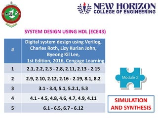
  • 1. SYSTEM DESIGN USING HDL (ECE43) # Digital system design using Verilog, Charles Roth, Lizy Kurian John, Byeong Kil Lee, 1st Edition, 2016, Cengage Learning 1 2.1, 2.2, 2.3 - 2.8, 2.11, 2.13 - 2.15 2 2.9, 2.10, 2.12, 2.16 - 2.19, 8.1, 8.2 3 3.1 - 3.4, 5.1, 5.2.1, 5.3 4 4.1 - 4.5, 4.8, 4.6, 4.7, 4.9, 4.11 5 6.1 - 6.5, 6.7 - 6.12 SIMULATION AND SYNTHESIS
  • 2. 01/02/2019 2Aravinda K., Dept. of E&C, NHCE, Bengaluru Delays in Verilog Inertial delay Transport delay Input pulse, that is shorter than the delay of the assignment, does not get propagated to the output. propagation delay of the gate delay due to the wire Input pulse gets transmitted to the output, after the assigned delay is added to it’s value. Net delay updation of the net’s value When the net takes the value from the driver, the value on the wire changes, after a delay.
  • 3. 01/02/2019 3Aravinda K., Dept. of E&C, NHCE, Bengaluru Delayed assignment = transport delay Delayed evaluation = inertial delay Illegal assignment RHS of the statement LHS of the statement
  • 4. 01/02/2019 4Aravinda K., Dept. of E&C, NHCE, Bengaluru Net delay gets added to the RHS after the inertial delay, because, the inertial delay is from the driver of the net. C1 rejects pulses that are less than 30 ns. C2 rejects pulses that are less than 20 ns. D rejects pulses that are less than 7 ns. E rejects pulses that are less than 3 ns.
  • 5. 01/02/2019 5Aravinda K., Dept. of E&C, NHCE, Bengaluru Compilation, simulation and synthesis Compilation: Checking of syntax and semantic rules (e.g., presence of semicolon, operation in between the signals of same type) Elaboration: Instantiation of modules (e.g., creation of driver for each signal, memory allocation for signals, interconnections among the ports) Simulation: Initialization of values for the signals, and then, the verification of the functionality of the modules
  • 6. 01/02/2019 6Aravinda K., Dept. of E&C, NHCE, Bengaluru  A design consists of connected threads of execution, called as processes.  The processes include modules, assignment statements, procedural blocks, system tasks etc.  A change in a signal is referred to as an “event”, and Verilog uses event-driven simulation.  During simulation, each change in the value of a net or a variable is called as “update event”.  When an “update event” is executed, all the processes that are sensitive to that event, are evaluated.  As events occur at different times, they are kept on an “event queue”, ordered by the “simulation time”.  The processing of all active events is called a “simulation cycle”.
  • 7. 01/02/2019 7Aravinda K., Dept. of E&C, NHCE, Bengaluru Name Contents of the region Example Active event region events that occur in the current simulation time (some events in this region, will be moved to the other regions, as per the event schedule) continuous assignments Inactive event region events that shall be processed after all the active events are processed blocking assignments without delay Non-blocking assign update region events that are assigned to the current simulation time, after all the active and inactive events are processed non-blocking assignments without delay Monitor event region events that shall be processed after all the active, inactive and non-blocking assign update events are processed $monitor, $strobe Future event region events that occur at some future simulation time blocking as well as non- blocking assignments with delay The Verilog event queue is segmented into five different regions
  • 8. 01/02/2019 8Aravinda K., Dept. of E&C, NHCE, Bengaluru  Events are added to the event queue in the source code order.  In this example, in the first module, the variable “a” will be assigned “0” after 5 ns, and “1” after another 5 ns.  In the second module, the two “always” blocks are concurrent, and hence there is no ordering. If a module contains more than one process, all processes execute concurrently.
  • 9. 01/02/2019 9Aravinda K., Dept. of E&C, NHCE, Bengaluru  If “initial” block is not specified, the variables would hold the value “x”.  “always” statement waits until a signal on the sensitivity list changes.  During an event, when no time delay is specified, Δ delay comes into picture.  In this code, as the “x” value of ‘B’ changes to “0”, the first “always” gets processed, and the value of ‘A’ changes to “1” after the Δ delay.  The second “always” also gets processed at the same time, and the value of ‘B’ changes to “1” after 10 ns.
  • 10. 01/02/2019 10Aravinda K., Dept. of E&C, NHCE, Bengaluru  For synthesis, it is not necessary to perform simulation.  The output of synthesis is the “netlist”, which is a list of the required components and their interconnections.  The netlist can be utilized to implement the digital system, by programming CPLD or FPGA.
  • 11. 01/02/2019 11Aravinda K., Dept. of E&C, NHCE, Bengaluru Simple Synthesis Examples Issues 1. The delay of 5 ns will not be present in the hardware, as “#5” does not get synthesized. If a delay has to be modeled, then counter has to be included in the code. 2. As ‘B’ is not present in the sensitivity list, the synthesized hardware will not produce any output whenever the value of ‘B’ changes. Thus, simulated output will be different from that of the synthesizer. Remedy Check for synthesizer warnings of missing signals in the sensitivity list. Example - 1 Verilog code Synthesized hardware
  • 12. 01/02/2019 12Aravinda K., Dept. of E&C, NHCE, Bengaluru Example - 2Verilog code Synthesized hardware Block diagram Internal circuitry 1. The values of ‘C’ and ‘G’ need to be retained after the positive edge of the clock. Therefore, flip-flops are required for both ‘C’ and ‘G’. 2. A change in the value of ‘C’ from statement-1 will not be considered during the execution of statement-2.
  • 13. 01/02/2019 13Aravinda K., Dept. of E&C, NHCE, Bengaluru Example - 3 If “clock” is omitted in the sensitivity list of an “always” statement, the synthesizer may produce latches instead of flip-flops. Hence, to reduce the number of flip-flops, it is better not to put the signal assignments in a clocked “always” statement. Example - 4 The synthesizer will create an empty blcok diagram, as the output ‘D’ is not at all assigned in the code. The synthesizer will give the following warnings:
  • 14. 01/02/2019 14Aravinda K., Dept. of E&C, NHCE, Bengaluru
  • 15. 01/02/2019 15Aravinda K., Dept. of E&C, NHCE, Bengaluru Declaration of constants in Verilog  There are three methods to define constant values: i) using the compiler directive `define, ii) using the keyword parameter, iii) using the keyword localparam. Note: Constants defined using parameter can be changed during module instantiation. For the constants which should not be changed, localparam is used to define them. i) `define constant_name constant_value e.g., `define wordsize 16 reg [1: `wordsize] data; Here, data is declared to be a reg of width wordsize. ii) parameter constant_name = constant_value; e.g., parameter msb = 15; parameter [31:0] decim = 1’b1; iii) localparam constant_name = constant_value; e.g., localparameter pi = 3.1416;
  • 16. 01/02/2019 16Aravinda K., Dept. of E&C, NHCE, Bengaluru Usage of arrays in Verilog  Digital VLSI circuits consist of repeated use of similar structures, and hence arrays can be utilized to model such structures, along with the required array bounds. Declaration reg [0:7] regA; // an 8-bit register. reg regB [0:7]; // an array of eight 1-bit registers. wire wire_arrayA [5:0]; // an array of six wires. integer intA [1:64]; // an array of sixty four integers. reg [7:0] regC [15:0]; // an array of sixteen 8-bit registers. Initialization regA = 8’b10010110; // 8-bit register’s contents. regC[15] = 8’b10100101; // 16th register’s 8-bit contents. . . . regC[0] = 8’b10010110; // 1st register’s 8-bit contents.
  • 17. 01/02/2019 17Aravinda K., Dept. of E&C, NHCE, Bengaluru Matrices  Matrices can be declared as multidimensional arrays. A matrix of size (4X3) with 8-bit elements is declared and initialized as follows – reg [7:0] matrixA [0:3][0:2] = {{4, 2, 9}, {1, 3, 4}, {8, 6, 7}, {5, 9, 2}};  The array element referenced as matrixA[2][1] implies the element that is in 3rd row and 2nd column, and it contains the value 6.  The arrays, along with the parameters, can be used to construct look-up tables (LUT), which can be used to create combinational circuits using ROM or LUT.
  • 18. 01/02/2019 18Aravinda K., Dept. of E&C, NHCE, Bengaluru Input (LUT Address) Output (LUT Data) 0000 00001 0001 00010 0010 00100 0011 00111 0100 01000 0101 01011 0110 01101 0111 01110 1000 10000 1001 10011 1010 10101 1011 10110 1100 11001 1101 11010 1110 11100 1111 11111 Example: odd parity representation for 4-bit numbers Verilog code for the example module parity_gen(X,Y); input [3:0] X; output [4:0] Y; wire paritybit; parameter [0:15] onebit = {1’b1, 1’b0, 1’b0, 1’b1, 1’b0, 1’b1, 1’b1, 1’b0, 1’b0, 1’b1, 1’b1, 1’b0, 1’b1, 1’b0, 1’b0, 1’b1}; assign paritybit = onebit[X]; assign Y = {X, paritybit}; Endmodule  As the first 4 bits of the output are identical to the input, it is not necessary to store all the 5-bit 16 numbers in the LUT.  Therefore, only the 16 parity bits can be stored, and the particular parity bit can be concatenated with the respective input bit.
  • 19. 01/02/2019 19Aravinda K., Dept. of E&C, NHCE, Bengaluru Usage of loops in Verilog  A system, in which an activity is happening in a repetitive fashion, can be represented by means of a loop.  The loop statements are sequential in nature. In Verilog, the keywords “forever”, “for”, “while” and “repeat” are used for the same.  There can be an infinite loop, as follows: begin clk = 1’b0; forever #10 clk = ~clk; end
  • 20. 01/02/2019 20Aravinda K., Dept. of E&C, NHCE, Bengaluru
  • 21. 01/02/2019 21Aravinda K., Dept. of E&C, NHCE, Bengaluru Testing a Verilog Model  A test bench is a separate Verilog code, which provides input combinations, to test a Verilog model.  In other words, the test bench is used during simulation, to provide stimuli to the system or circuit under test.  The test bench module does not have external inputs and outputs, and hence the port list in the module declaration, will be empty. Example: 4-bit adder An exhaustive test of this adder requires 512 tests (16 numbers of Addend X 16 numbers of Augend X 2 values of Carry-in). Design Under Test Test bench (Top module)
  • 22. 01/02/2019 22Aravinda K., Dept. of E&C, NHCE, Bengaluru Test bench program with a random set of 11 tests
  • 23. 01/02/2019 23Aravinda K., Dept. of E&C, NHCE, Bengaluru
  • 24. 01/02/2019 Aravinda K., Dept. of E&C, NHCE, Bengaluru 24 Verilog Functions  A function returns only a single value, and a function cannot contain delays.  Functions and tasks can be defined in the module that they will be used in.  A function call in the program file can happen just like an expression.  A function can call other functions, but the function cannot call tasks.  If a function or a task is defined as a separate file, then the compiler directive `include has to be used in the program file. Example-1: Write a function for generating an even parity bit for a 4-bit number. function [4:0] even_parity; input [3:0] A; reg temp; begin temp = A[0]^A[1]^A[2]^A[3]; even_parity = {A, temp}; end endfunction module even_test(Z); output reg [4:0] Z; reg [3:0] INP; initial begin INP = 4’b0101; Z = even_parity(INP); end endmodule
  • 25. 01/02/2019 Aravinda K., Dept. of E&C, NHCE, Bengaluru 25 Example-2: Write a function to add two 4-bit numbers function [4:0] add4; input [3:0] A,B; input cin; reg [4:0] sum; reg cout; begin integer i; for (i=0; i<=3; i=i+1) begin cout = (A[i] & B[i]) | (B[i] & cin) | (A[i] & cin); sum[i] = A[i] ^ B[i] ^ cin; cin = cout; end sum[4] = cout; add4 = sum; end endfunction Function call: i) Z <= add4(X, Y, 0); // for adding Y to Z ii) Z <= add4(X, ~Y, 1); // for subtracting Y from Z, ignoring Z[4]
  • 26. 01/02/2019 Aravinda K., Dept. of E&C, NHCE, Bengaluru 26 Example-3: Write a program which computes the square of a 4-bit number, by using a function module squares_test (clk); input clk; reg [3:0] temp; reg [7:0] answer; function [7:0] squares; input [3:0] number; begin squares = number * number; end endfunction initial begin temp = 4’b0011; end always @(posedge clk) begin answer = squares (temp) end endmodule  A function must have at least one input argument.  The function cannot have output or inout arguments.  Recursive functions must be declared as automatic.
  • 27. 01/02/2019 Aravinda K., Dept. of E&C, NHCE, Bengaluru 27 Verilog Tasks  Unlike functions, the tasks can return any number of values.  Tasks can contain delay, event and timing control statements.  Tasks can have arguments of type input, output and inout. This task adds two 4-bit numbers. Task call:
  • 28. 01/02/2019 Aravinda K., Dept. of E&C, NHCE, Bengaluru 28 Function Task At least one input argument, but no output or inout arguments Any number of input, output or inout arguments Returns a single value by assigning the value to the function name Passes multiple values that are declared inside Can call other functions, but cannot call tasks Can call other functions or tasks Cannot contain any time- controlled statements Can contain time-controlled statements Executes in zero simulation time Executes in non-zero simulation time
  • 29. 01/02/2019 29Aravinda K., Dept. of E&C, NHCE, Bengaluru Name Function $display Prints the test’s results on the screen, exactly after execution, and then adds a newline character $write Prints the test’s results on the screen, exactly after execution, but does not add a newline character $strobe Prints the test’s results on the screen, at the end of the current simulation time $monitor Prints the test’s results on the screen, every time when one of its parameters changes System tasks to observe the outputs
  • 30. 01/02/2019 30Aravinda K., Dept. of E&C, NHCE, Bengaluru System tasks to observe the outputs $display(“Simulation time is %t”, $time); $display(“Simulation time is %t”, $time); Simulation time is 10 Simulation time is 11 $write(“Simulation time is %t”, $time); $write(“Simulation time is %t”, $time); Simulation time is 10 Simulation time is 11
  • 31. 01/02/2019 31Aravinda K., Dept. of E&C, NHCE, Bengaluru always@(posedge reset) $strobe(“The FlipFlop value is %b at time %t”, q, $time); The FlipFlop value is 1 at time 17 The FlipFlop value is 0 at time 24 The FlipFlop value is 1 at time 26 initial $monitor(“At %t, d=%d, clk=%d”, $time, d, clk, “and q is %b”, q); At 24, d=x, clk=x and q is 0 At 25, d=x, clk=x and q is 1 At 30, d=0, clk=x and q is 1 At 35, d=0, clk=1 and q is 1 At 40, d=0, clk=0 and q is 1
  • 32. 01/02/2019 32Aravinda K., Dept. of E&C, NHCE, Bengaluru