Download as PDF, PPTX


The document discusses the optimization of rear twist beam (RTB) designs for vehicle suspensions. It describes Gestamp's process of using optimization software to design RTBs that meet requirements for roll stiffness, roll steer, durability, packaging space, and mass. The process eliminates initial trial and error CAD work. It then focuses on optimizing the reinforcer length, torsion element gauge, and local edge shapes to minimize stress and mass while satisfying the rollover and fatigue targets. The optimized design process allows Gestamp to quickly develop competitive low-cost, low-mass RTB designs.
Introduction to the Optimized Rear Twist Beam (RTB) design, highlighting Gestamp's global presence and chassis products.
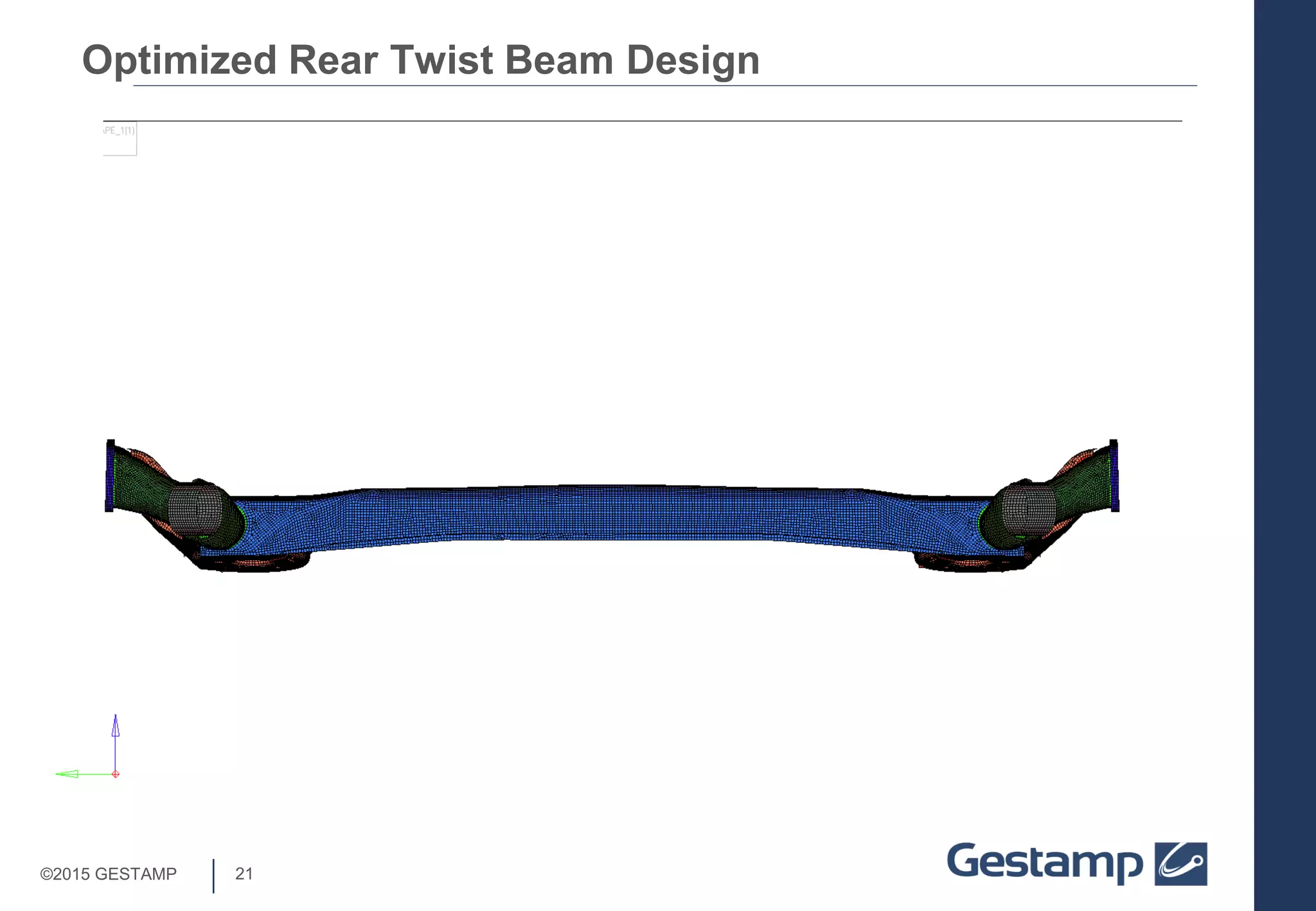
Introduction of the RTB suspension system's components, advantages, and the design's basis.
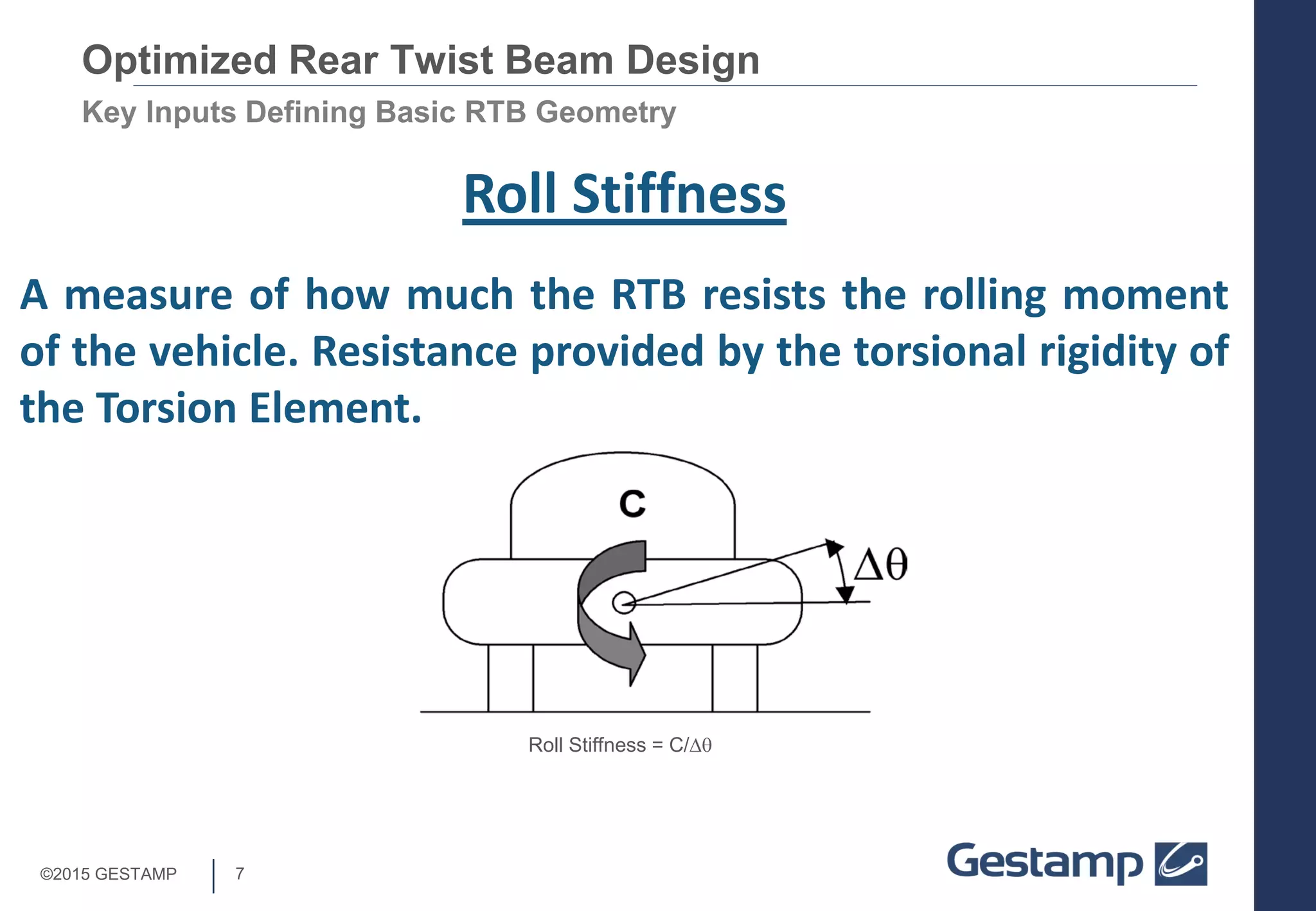
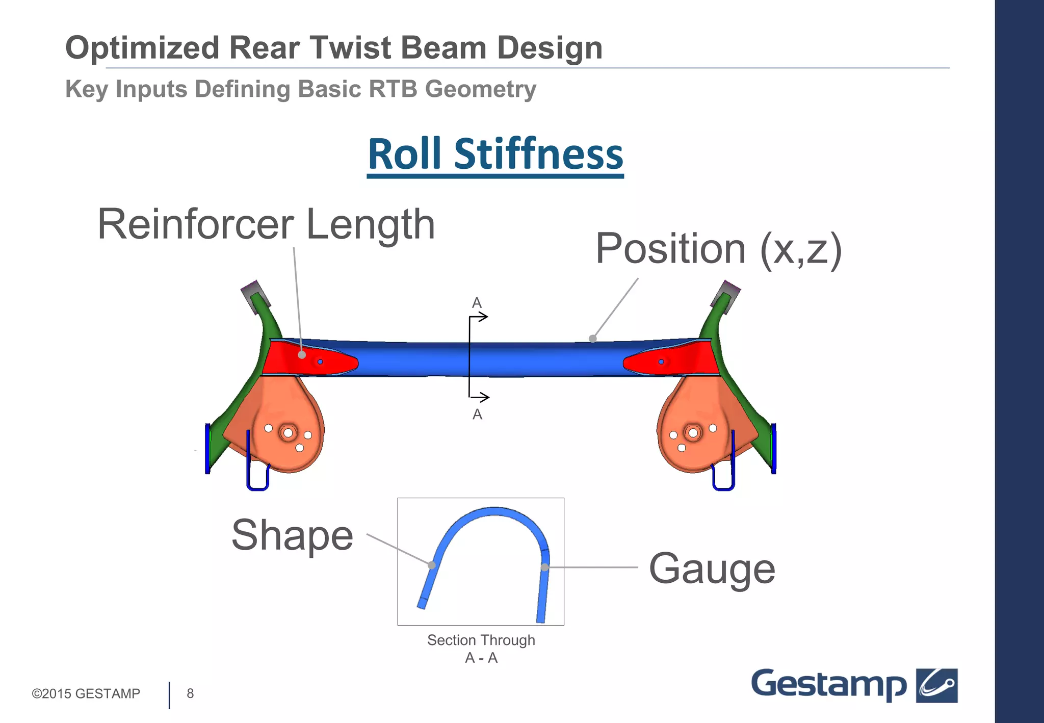
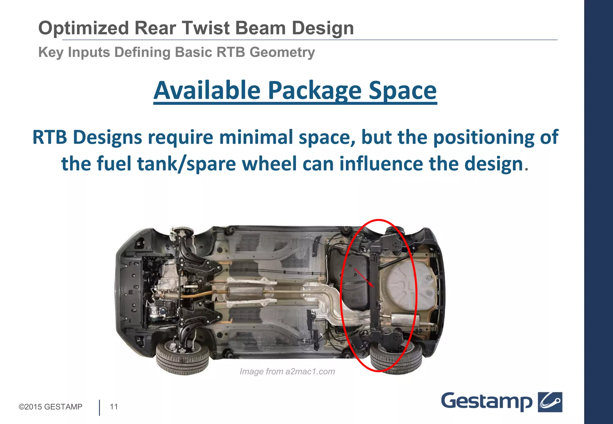
Discussion on important inputs defining RTB geometry including roll stiffness, roll steer, and space constraints.
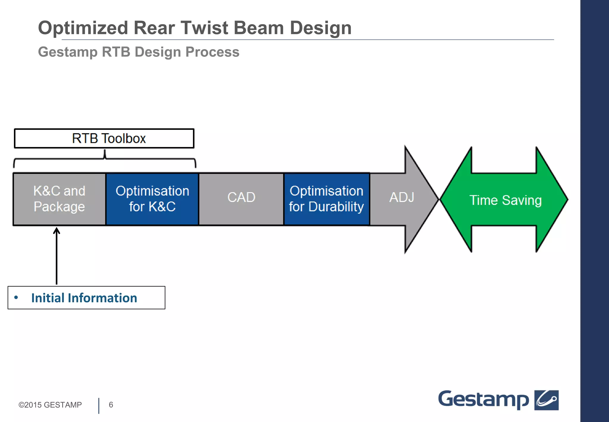
Gestamp's collaboration with Altair to enhance RTB design processes through optimization and elimination of trial and error.
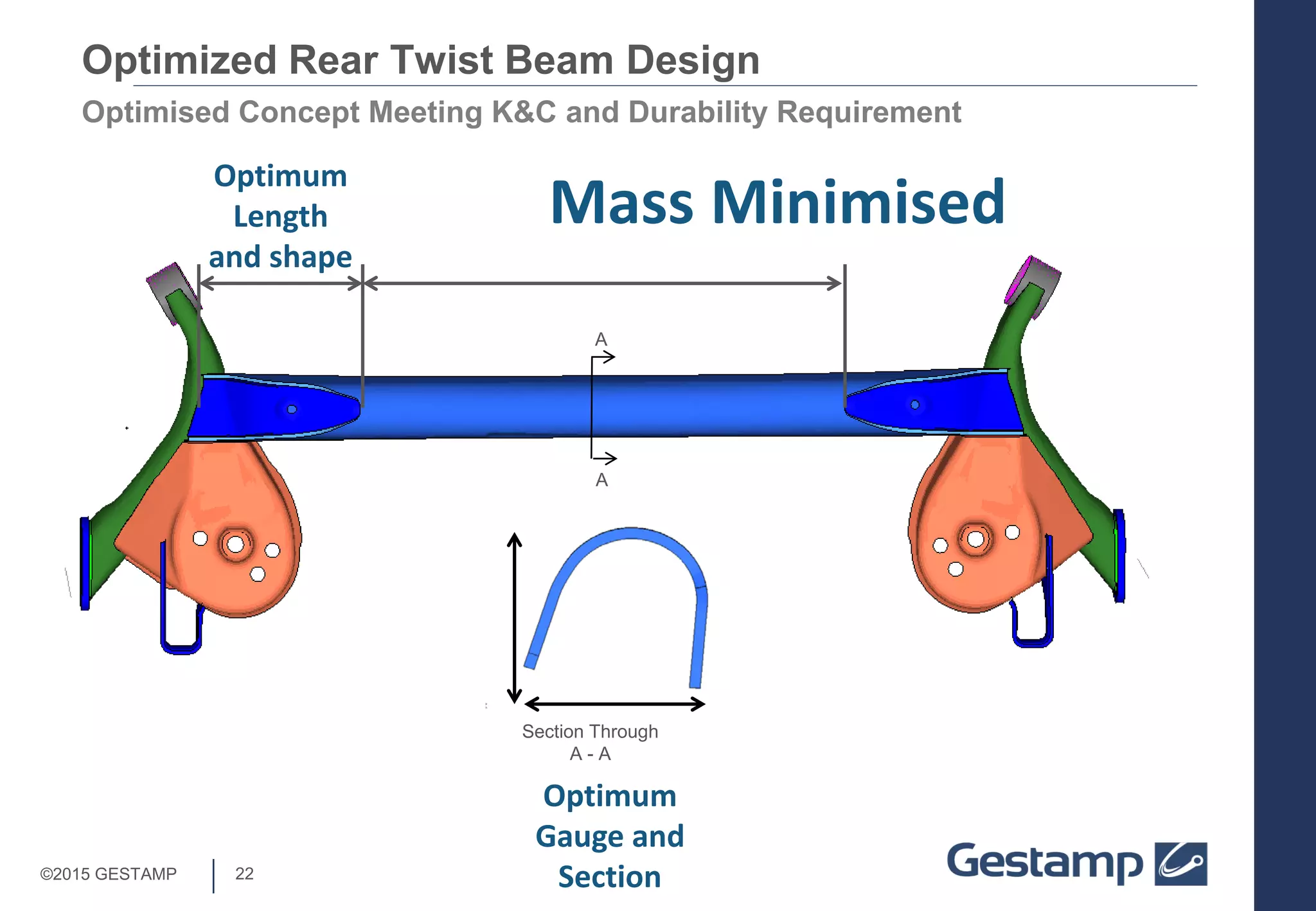
Balancing roll stiffness and antiphase durability through the optimization of length and gauge of structural elements.
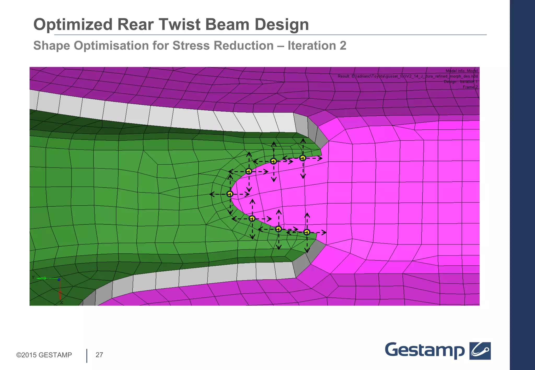
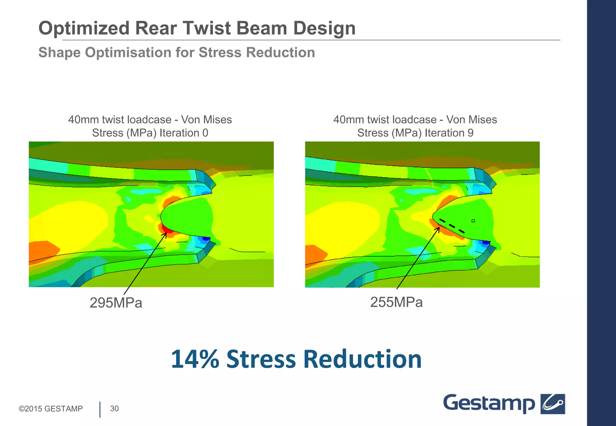
Focus on shape optimization iterations to reduce stress in the design, achieving a 14% reduction in maximum stress.
Summary of how the optimized design process enables quick adaptation and realization of cost-effective RTB systems.


