1. Members in the
group: -MOHAMED OSAMA ALSAMSAM - YASSER MONJED
- MOHAMED SALAH RAGAB - ALAA IBRAHIM
-SHADY HESHMET - BADR SAYYID
- SAYYID KHAIRY - MOHAMED KAMEL
- ASSAYYID FATHY - ASSEM HUSSIEN
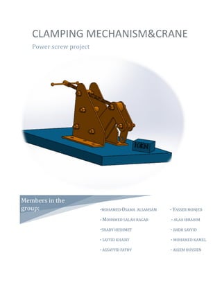
CLAMPING MECHANISM&CRANE
Power screw project
2. TABLE OF CONTENTS
Contents:
1- INTRODUCTION. 1
2- PROJECT PROCEDURE 3
3- POWER SCREW DESIGN 4
4- FRAME DESIGN. 17
5- PARTS AND ASSEMBELY IN SOLIDWORKS. 22
6- STRESS ANALYSIS IN SOLIDWORKS. 25
7- PROJECT APPLICATION. 26
8- REFRENCES 27
3. 1-INTRODUCTION
Page 1
1-INTRODUCTION
If the point of contact between the product and people become a
point of friction, then the industrial designer has failed.
On the other hand, if people are made safer, more efficient, more
comfortable, by contact with the product, then the designer has
succeeded.
Henry Dreyfuss, 1967.
A screw thread is formed by cutting continuous helical groove on
cylindrical face. A screw made by cutting a single helical groove in
cylinder is known as (single threaded) .
And similarly (double threaded and triple quadruple)
May be cut either right hand or lift hand.
A screwed joint is mainly compost of two elements i.e. a bolt and
nut (you can see them in project paper sheet)
4. 1-INTRODUCTION
Page 2
We will use metric standard to produce our thread:
Metric Threads standard
The steps which the team go on it:
1- The primary drawing (Sayyid khairy + M.kamel)
2- The power screw design (M.salah +Alaa Ibrahim)
3- The frame design (M.Osama + Yasser Monjed)
4- The solid works drawing (assayyid fathy + Assem Hussin)
5- The Report writing (Shady heshmet + Badr sayyid)
So, The design of Machine clamp is done.
Finally Working and revision is done by
(assayyid fathy + M.Salah + Sayyid khairy)
In 1/2/2018. The project was done.
In 10/2/2018.The revision was done
5. 2- PROJECT PROCDURE
Page 3
2- PROJECT PROCDURE
A- Purpose of project (clamping or lifting)
Its limitation (W=18KN; L=500mm)
B- Product concept (3F)(Form+feature+function)
C- Nature of Load (static load)
D- Appropriate material (Next pages)
E- Force analysis, stress analysis and mode of
failure (Next pages)
F- DFM and DFA Page22
G- Detail drawing (Paper sheet A1)
6. 3- POWER SCREW DESIGN
Page 4
3- POWER SCREW DESIGN
The thread is trapezoidal because:
1. The efficiency of trapezoidal is high
2. If there are any corrosion in thread. it’s no problem
Given
W = 18 KN
Max. L = 500 mm
Full design (screw)
Full design (nut)
Handle
A- Screw (material, size, modes of failure)
1-material (P.175)
AISI 1015
Condition: cold drawn
7. 3- POWER SCREW DESIGN
Page 5
u = 420 Mpa f.S = 3
y = 314 Mpa f.S = 3 × 0.6 = 1.8
E = 205 Gpa
2-size
dc Ac
3- Modes of failure:
a) Compression failure
c =
𝑤
𝐴𝑐
≤
σy
𝑓. 𝑠
AT standard P.184
c =
𝑤
𝐴𝑐
≤
σy
𝑓. 𝑠
18 x103
Ac
≤
314
1.8
103.18 mm2
≤ Ac
AT table P.185
8. 3- POWER SCREW DESIGN
Page 6
Trapezoidal
Then:
Ac = 105mm2
do = 16mm
dc = 11.5 mm
p = 4mm
b) Buckling failure
W cr ≥ wgiven
wcr =
π
2
EI
𝑙𝑒2
≥ wgiven
I =
π
64
( dcore )4
Le = K × L
AT p. 159
K = 2 (fixed free)
9. 3- POWER SCREW DESIGN
Page 7
Le = 2 × 500 = 1000mm
Wcr =
π
2
EI
𝑙𝑒2
=
π
2
205∗103
10002
×
π ×11.44
64
Wcr = 1737.06 N Wcr = .1.737 KN
But wgiven = 18 KN
Wcr ≥ wgiven
Then Wcr = wgiven
π
2
205×103
1000^2
×
π(dc)4
64
= 18000
Dc = 20.633 mm
AT P.185
do = 28mm dc = 22.5mm
p = 5 mm A=389mm2
14. 3- POWER SCREW DESIGN
Page 12
Se ≤ all
Safe design
B- NUT
Material
Select malleable cast iron p.178
ASTM class 47 y = 224Mpa
1-Bearing /crushing mode
b =
𝑤
𝐴𝑝
≤ all ≤
σy
𝐹∗𝑠
Ap = π/4 (do2 – dc2 ) * Z1
H=Z * p
4∗𝑤
𝜋(282−22.52)∗𝑍1
≤
224
6
F.S=10*.6=6
Z1 = 2.43 = 4 even number
H1= Z1*P = 4*5=20mm
2 - shearing mode (strip off) transverse shear
Τmax =
3 w
π d h
≤ τall =
0.5 σy
f.s
15. 3- POWER SCREW DESIGN
Page 13
3 × 18× 103
π × 22.5 × 5× z
≤
0.5 ×224
6
z2 = 8.18 ≈ 10
H2 = 10 × 5 = 50 mm
b = 1.6 do b = 1.6 × 28 = 44.8 mm
Through (Crashing, strip off)
see its (safe or not)
3 – combined stress:
Se = √σb + 3 τ ≤ σall =
σy
f.s
σb =
4 w
π ×(do2−dc2 ) z
=
4 × 18 × 103
π ×( 282−22.52) 10
σb = 8.251 Mpa
τmax =
3 w
π d h
=
3 × 18× 103
π ×22.5 ×50
τmax = 15.279 Mpa
σall =
σy
f.s
=
224
6
=37.33 Mpa
check :
se =√(8.251)2 + 3(15.279)2 = 27.72Mpa
16. 3- POWER SCREW DESIGN
Page 14
∴ se < σall ∴ its safe design
c – handle:
need to get 1- length of the arm
2- diameter of the arm
3- handle material
1 - human force: (200: 400) N
Assume 300 N
Τtot = f . LH
LH =
Τtot
f
=
108.9075 × 10³
300
= 363.03mm arm length
2 - dh = 0.5 do
dh = 0.5 × 28 = 14 mm
3 - material
According to stress we select the material
Se = √σb + 3 τ ≤ σall =
σy
f.s
17. 3- POWER SCREW DESIGN
Page 15
σy = ? ? ?
σb =
𝐌∗ 𝐲
𝑰
y=dh/2
M = F × LH = 300 × 363.025 = 108907.5 N.mm
I =
π
64
( dh )4
=
π
64
( 14)4 = 1885.74 mm4
σb =
108907.5 × 7
1885.75
= 404.27 Mpa
τ =
𝐹
𝐴
=
4 f
π ×d (h)2 =
4 ×300
π × (14)2 = 1.949 Mpa
(direct shear)
se = √(404.27)2 + 3(1.949)2 = 404.284 Mpa
then get σy
then from table page 177 choose the material
se ≤
σy
1.8
22. 4- FRAME DESIGN
Page 20
AT sec A-A: θ = 90
∑ fx = 0 ph= 9000 N
Stress analysis:
σt =
9000
10∗100
= 9 Mpa
at section B-B:
∑ fy = 0 pv = 9000 N
∑ mz = 0 mz = 9000 × 350 = 3.1*106 N.mm
Stress analysis :
σb =
m y
𝐼
, I =
1
12
× 10 × 2003 , y =
200
2
= 100 mm
σb = ±
3.1∗106×100
1
12
× 10 × 2003
= ± 46.5 Mpa
23. 4- FRAME DESIGN
Page 21
τ =
3V
2𝐴
=
3 × 9000
2 × 10 × 200
= 6.75 Mpa
by mohr :
σ1 =47 MPa , σ2 = -1 MPa
Bearing failure: “bolts)
σt =
𝐹
( 𝐵−𝑛∗𝑑) 𝑡𝑚𝑖𝑛
≤ σall
=
9000
(100−1∗40)∗10
= 15 Mpa
*steel Material
(AISI1006) cold drawn
σy =285 MPa F.S= 3*.6=1.8
σall= 285/1.8 = 158.3 Mpa
Max stress at θ=zero 76.5 ≤ σall safe design
F: applied force
B: width of plate
n: no. of bolts
d: dia of bolt
tmin: min. thickness of
plate .
24. 5- PARTS AND ASSEMBLY IN SOLIDWORKS.
Page 22
5- PARTS AND ASSEMBLY IN SOLIDWORKS.
We used solid works 2016 to design
parts and make assembly for this parts.
The mission includes:
1- The sketching and feature:
Many tool is used
25. 5- PARTS AND ASSEMBLY IN SOLIDWORKS.
Page 23
2- The main parts are designed:
- Support - Arm
Screw
3- Selecting the material
26. 5- PARTS AND ASSEMBLY IN SOLIDWORKS.
Page 24
5- Assembly working
27. 6- STRESS ANALYSIS IN SOLIDWORKS.
Page 25
6- STRESS ANALYSIS IN SOLIDWORKS.
Using a study advisor (static – Buckling. etc.)
28. 7- PROJECT APPLICATION.
Page 26
7- PROJECT APPLICATION.
- In the work shop machines. Is used to
lifting working piece.
- with some editing. In the production lines
to transport the product from line to
another (put on rotating disk)
- with some editing. As machine clamp.
- Fully controlled of large work piece.
29. 9- REFRENCES
Page 27
9- REFRENCES
Machine Design R.S Khurmi 2010
Design of machine elements for prof DR. Abdelhay M.
Abdehay.
Part and Assembly Modeling with SOLIDWORKS 2015
Huei-Huang Lee
YouTube videos
Shigley's Mechanical Engineering Design 9th Edition +
Solutions
MACHINE DRAWING BOOK
Dr. K.L.Narayana
Dr. P. kannaiash
Dr. Venkata Reddy