
Recommended
More Related Content
What's hot
What's hot (20)
Similar to Threaded Fastners.pdf
Similar to Threaded Fastners.pdf (20)
Recently uploaded
Recently uploaded (20)
Threaded Fastners.pdf
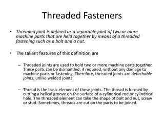
- 1. Threaded Fasteners • Threaded joint is defined as a separable joint of two or more machine parts that are held together by means of a threaded fastening such as a bolt and a nut. • The salient features of this definition are – Threaded joints are used to hold two or more machine parts together. These parts can be dismantled, if required, without any damage to machine parts or fastening. Therefore, threaded joints are detachable joints, unlike welded joints. – Thread is the basic element of these joints. The thread is formed by cutting a helical groove on the surface of a cylindrical rod or cylindrical hole. The threaded element can take the shape of bolt and nut, screw or stud. Sometimes, threads are cut on the parts to be joined.
- 2. advantages of threaded joints • The parts are held together by means of a large clamping force. There is wedge action at the threads, which increases the clamping force. There is no loosening of the parts. Therefore, threaded joints are ‘reliable’ joints. • The parts are assembled by means of a spanner. The length of the spanner is large compared with the radius of the thread. Therefore, the mechanical advantage is more and force required to tighten the joint is small. • Threaded joints have small overall dimensions resulting in compact construction. • The threads are self-locking. Therefore, threaded joints can be placed in any position—vertical, horizontal or inclined. • Threaded fasteners are economical to manufacture. Their manufacturing is simple. High accuracy can be maintained for the threaded components. • The parts joined together by threaded joints can be detached as and when required. This requirement is essential in certain applications for the purpose of inspection, repair or replacement. • Threaded fasteners are standardized and a wide variety is available for different operating conditions and applications.
- 3. disadvantages of threaded joints • Threaded joints require holes in the machine parts that are to be clamped. This results in stress concentration near the threaded portion of the parts. Such areas are vulnerable to fatigue failure. • Threaded joints loosen when subjected to vibrations. • Threaded fasteners are considered as a major obstacle for efficient assembly. In manual assembly, the cost of tightening a screw can be six to ten times the cost of the screw itself. • Therefore, Design for Manufacture and Assembly (DFMA) recommends minimum number of threaded fasteners.
- 4. parts of a threaded fastening • There are three parts of a threaded fastening, viz., a bolt or screw, a nut and a washer • A bolt is a fastener with a head and straight threaded shank and intended to be used with a nut to clamp two or more parts. • The same bolt can be called screw when it is threaded into a tapped hole in one of the parts and not into the nut. • A nut is a small symmetrical part, usually having hexagonal or square shape, containing matching internal threads. • Simple washers are thin annular shaped metallic disks. The functions of a washer are as follows: – It distributes the load over a large area on the surface of clamped parts. – It prevents marring of clamped parts during assembly. – It prevents marring of the bolt head and nut surface during assembly. – It provides bearing surface over large clearance holes.
- 5. types of threaded fastenings • Through Bolts A through bolt is simply called a ‘bolt’ or a ‘bolt and nut’. The bolt consists of a cylindrical rod with head at one end and threads at the other. The cylindrical portion between the head and the threads is called shank. The shank passes through the holes in the parts to be fastened. The threaded portion of the bolt is screwed into the nut. • Tap Bolts and Cap Screws There is a basic difference between through bolt and tap bolt. The • tap bolt is turned into a threaded (tapped) hole in one of the parts being connected and not into a • nut. • Studs A stud is a cylindrical rod threaded at both ends. One end of the stud is screwed into the tapped hole in one of the connecting parts. The other end of the stud receives a nut.
- 6. Cap screws • Cap screws differ from tap bolt in the following respects: – Cap screws are small compared with tap bolt. – A wide variety of shapes are available for the head of cap screw. On the other hand, tap bolt has hexagonal or square head. • Depending upon the shape of the head, cap screws are divided into the two groups: – cap screws in which the head is engaged externally by a spanner; – cap screws in which the head is engaged internally and from the end face.
- 7. Set screws • Setscrew is used to prevent relative motion between two parts. The threaded portion of the setscrew passes through a tapped hole in one of the parts and the end of the screw presses against the other part. The end of the screw is called the point of the screw. • Setscrews differ from cap screws in the following respects: – Setscrews are subjected to compressive force only. Cap screws are subjected to tensile and shear forces. – Setscrew transmits force from threaded component to the other mating component by means of screw point. In cap screw, the force is transmitted by the head. – Setscrews are short and threaded over full length of the shank compared with the cap screws.
- 8. BOLT OF UNIFORM STRENGTH • Bolts are subjected to shock and impact loads in certain applications. i.e. The bolts of cylinder head of an internal combustion engine or the bolts of connecting rod. • In such cases, resilience of the bolt is important design consideration to prevent breakage at the threads. • Resilience is defined as the ability of the material to absorb energy when deformed elastically and to release this energy when unloaded. • A resilient bolt absorbs energy within elastic range without any permanent deformation and releases this energy when unloaded. It can be called spring property of the bolt. A resilient bolt absorbs shocks and vibrations like leaf springs of the vehicle. In other words, the bolt acts like a spring. • When this bolt is subjected to tensile force, there are two distinct regions of stress. They are as follows: • The diameter of threaded portion dc is less than the shank diameter d. The threaded portion is also subjected to stress concentration. Therefore, stress induced in the threaded portion is more than the stress in the shank portion. The energy absorbed by each unit volume of bolt material is proportional to the square of the stress.Hence, a large part of the energy is absorbed in the threaded portion of the bolt. • The diameter of the shank is more than the core diameter of the threaded portion. There is no stress concentration in the shank. Therefore, when the bolt is subjected to tensile force, the stress in the shank portion is less than the stress in the threaded portion. The energy absorbed in the shank, which is proportional to the square of the stress, is less than the energy absorbed in the threaded part.
- 9. BOLT OF UNIFORM STRENGTH • The ideal bolt will be one which is subjected to same stress level at different cross-sections in the bolt. It is called the bolt of uniform strength. • In a bolt of uniform strength, the entire bolt is stressed to the same limiting value, thus resulting in maximum energy absorption. • There are two ways to reduce the cross-sectional area of the shank and convert an ordinary bolt into a bolt of uniform strength. – One method is to reduce the diameter of the shank – another method, the cross-sectional area of the shank is reduced by drilling a hole. Both methods reduce cross-sectional area of the shank and increase stress and energy absorption.
- 12. Types of Threads
- 18. Metric Threads • Metric threads are divided into coarse and fi ne series. The coarse thread is considered as the basic series. • The static load carrying capacity of coarse threads is higher. • Coarse threads are easier to cut than fi ne threads. • The errors in manufacturing and wear have less effect on the strength of coarse threads than that of fi ne threads. • Coarse threads are less likely to seize during tightening. • Coarse threads have more even stress distribution. • Fine threads offer the following advantages: • Fine threads have greater strength when subjected to fluctuating loads. • Fine threads have greater resistance to unscrewing as a result of lower helix angle. Therefore, threads with fi ne pitch are more dependable than threads with coarse pitch in respect of self-unscrewing.
- 19. Designation of Metric Threads • A screw thread of coarse series is designated by the letter ‘M’ followed by the value of the nominal diameter in mm. For example, M 12 • A screw thread of fine series is specified by the letter ‘M’, followed by the values of the nominal diameter and the pitch in mm and separated by the symbol ‘X’. For example, M 12 X 1.25
- 22. Stress Analysis • A bolted joint subjected to tensile force P, The cross-section at the core diameter dc is the weakest section. • The maximum tensile stress in the bolt at this cross-section is given by
- 23. Stress Analysis • The height of the nut h can be determined by equating the strength of the bolt in tension with the strength in shear. The procedure is based on the following assumptions: – Each turn of the thread in contact with the nut supports an equal amount of load. – There is no stress concentration in the threads. – The yield strength in shear is equal to half of the yield strength in tension (Ssy = 0.5Syt). – Failure occurs in the threads of the bolt and not in the threads of the nut.
- 24. Stress Analysis • The threads of the bolt in contact with the nut are sheared at the core diameter dc. The shear area is equal to (πdc h), where h is the height of the nut. • The strength of the bolt in shear is given • Equating both strength, h = 0.5dc • Assuming (dc = 0.8d), h = 0.4d • Therefore, for standard coarse threads, the threads are equally strong in failure by shear and failure by tension, if the height of the nut is approximately 0.4 times of the nominal diameter of the bolt. • The height of the standard hexagonal nut is (0.8d). Hence, the threads of the bolt in the standard nut will not fail by shear. • Thus height of the standard nut, h = 0.8d
- 25. Bolt Joints under Eccentric Loading
- 26. Eccentric Load Parallel to axis of Bolt
- 28. Eccentric Load Perpendicular to Bolt Axis