SlideShare a Scribd company logo
1 of 26
DESIGN OF STEEL STRUCTURES 13
UNIT II
BOLTED CONNECTIONS
A bolt may be defined as a metal pin with a head at one end and a shank threaded at the other
end to receive a nut as in Fig 1.0(a). Steel washers are usually provided under the bolt as well as
under the nut to serve two purposes:
1. To distribute the clamping pressure on the bolted member, and
2. To prevent the threaded portion of the bolt from bearing on the connecting pieces.
In order to assure proper functioning of the connection, the parts to be connected must be tightly
clamped between the bolt between the bolt head and nut. If the connection is subjected
Smartworld.asia Specworld.in
Smartzworld.com jntuworldupdates.org
1
DESIGN OF STEEL STRUCTURES 14
vibrations, the nuts must be locked in position. Bolted connections are quit similar to riveted
connections in behaviour but have some distinct advantages as follows:
1. The erection of the structure can be speeded up, and
2. Less skilled persons are required.
The general objections to the use of bolts are:
1. Cost of material is high: about double that of rivets.
2. The tensile strength of the bolt is reduced because of area reduction at the root of the
thread and also due to stress concentration.
3. Normally these are of a loose fit excepting turned bolts and hence their strength is
reduced.
4. When subjected to vibrations or shocks bolts may get loose.
Uses
1. Bolts can be used for making end connections in tensions and compression member.
2. Bolts can also be used to hold down column bases in position.
3. They can be used as separators for purlins and beams in foundations, etc.
Types
There are several types of bolts used to connect the structural elements. Some of the bolts
commonly used are:
a) Unfinished bolts
b) Turned bolts
Smartworld.asia Specworld.in
Smartzworld.com jntuworldupdates.org
2
DESIGN OF STEEL STRUCTURES 15
c) Ribbed bolts
d) High strength bolts
e) Interference bolts
UNFINISHED BOLTS
Unfinished bolts are also called ordinary, common, rough or black bolts. There are used for light
structures (purlins, bracings, etc.) under static loads. They are not recommended for connections
subjected to impact load, vibrations and fatigue. Bolts are forged from low carbon rolled steel
circular rods, permitting large tolerances. Ordinary structural bolts are made from mild steel with
square or hexagonal head, as shown in Fig 1.0(b). Square heads cost less but hexagonal heads
give a better appearance, are easier to hold by wrenches and require less turning space. The bolt
hole is punched about 1.6mm more than the bolt diameter. The nuts on bolts are tightened with
spud wrenches, producing little tension. Therefore, no clamping force is induced on the sections
jointed. Sometimes a hole is drilled in the bolt and a cotter pin with a castellated nut is used to
prevent the nut from turning on the bolt, as shown in Fig 1.0(c). the connections with unfinished
bolts are designed in a similar way as all the riveted connections except that the permissible
stresses are reduced to account for tolerances provide on shank and threaded portion of the bolts.
The requirements regarding pitch and edge distance are same as that for rivets. The permissible
stresses are as given in Table 8.1 of I.S:800-1984.
TURNED BOLTS
These are similar to unfinished bolts, with the differences that the shank of these bolts is formed
from a hexagonal rod. The surfaces of the bolts are prepared carefully and are machined to fit in
the hole. Tolerances allowed are very small. These bolts have high shear and bearing resistance
as compared to unfinished bolts. However, these bolts are obsolete nowadays. The specifications
for turned bolts are given in I.S:2591-1969.
RIBBED BOLTS
These are also called fluted bolts. The head of the bolt is like a rivet head. The threaded and nut
are provided on the other end of the shank. From the shank core longitudinal ribs project making
the diameter of the shank more than the diameter of the hole. These ribs cut grooves into the
connected members while tightening and ensure a tight fit. These bolts have more resistance to
Smartworld.asia Specworld.in
Smartzworld.com jntuworldupdates.org
3
DESIGN OF STEEL STRUCTURES 16
vibrations as compared to ordinary bolts. The permissible stresses for ribbed are same as that for
rivets.
HIGH STRENGTH BOLT
These bolts are called friction grip bolts. These are made from bars of medium carbon steel.
Their high strength is achieved through quenching and tempering processes or by alloying steel.
Steel washers of hard steel or carburized steel are provided as shown in Fig1.0 (d), to evenly
distribute the clamping pressure on the bolted member and to prevent the threaded portion of the
bolt from bearing on the connecting pieces. If the bolts are tightened by the turn of nut method,
the nut is made snug and is tightened a half turn more by hand wrenches, then the washers are
not required. The vibrations and impact resistance of the joint is also improved. The nut and head
of the bolts are kept sufficiently large to provide an adequate bearing area. The specifications for
high strength bolts are laid in I.S:3757-1972 and I.S: 4000-1967. These bolts have a tensile
strength several times that of the ordinary bolts. High strength bolts have replaced rivets and are
being used in structures, such as high rise buildings, bridges, machines etc. Due to their distinct
advantages and vital use, high strength bolts are discussed below in some detail.
Advantages of high strength bolts
High strength friction grip (HSFG) bolts have replaced the rivets because of their distinct
advantages as discussed below. However, the material cost is about 50% greater than that of
ordinary bolts and special workmanship is required in installing and tightening these bolts.
1. These provide a rigid joint. There is no slip between the elements connected
2. Large tensile stresses are developed in bolts, which in turn provide large clamping force
to the elements connected. High frictional resistances is developed providing a high static
strength the joint.
3. Because of the clamping action, load is transmitted by friction only and the bolts are not
subjected to shear and bearing.
Smartworld.asia Specworld.in
Smartzworld.com jntuworldupdates.org
4
DESIGN OF STEEL STRUCTURES 17
4. The frictional resistance is effective outside the hole and therefore lesser load is
transmitted through the net section. Thus, the possibility of failure at the net section is
minimized.
5. There are no stress concentrations in the holes; therefore, the fatigue strength is more.
6. The tension in bolts is uniform. Also the bolts are tensioned up to proof load hence; the
nuts are prevented from loosening
7. Few persons are require to make the connections, thus cost is reduced.
8. Noise nuisance is not there as these bolts are tightened with wrenches.
9. The hazard of fire is not there and there is no danger of tossing of the bolt.
10. Alterations can be done easily.
11. For some strength, lesser number of bolts are required as compared to rivets which brings
overall economy.
Principles of high strength bolts
The shank of the high strength bolts does not fully fill the hole. So shear and bearing are not the
criteria for load transmission as is in the case of rivets, which fill the hole completely. The nut is
tightened to develop a clamping force on the plates which is indicated as the tensile force T in
the Bolt. This tension should be about 90% of proof load. When a shear load is applied to the
joint no slip will occur until the shear load exceeds the frictional resistance between the elements
jointed. When shear load exceeds the frictional resistance a slip occurs. On further increase of
this load, the gradual slipping brings the bolt in contact with the plate edges.
The horizontal frictional forces F, is induced in the joints which is equal to the tensile force T, as
in Fig.1.0(d), in the bolts multiplied by the coefficient of friction.
F = µT
This frictional force F should exceed the applied force P on the member.
Smartworld.asia Specworld.in
Smartzworld.com jntuworldupdates.org
5
DESIGN OF STEEL STRUCTURES 18
µ= Coefficient of friction or slip factor, is defined as ratio of the load per effective interface
required to produce slip in a pure shear joint to the proof load induced in bolt. When the element
surfaces are free from paint, dust, etc. its value is 0.45.
PIN CONNECTIONS
When two structural members are connected by means of a cylindrical shaped pin, the
connection is called a pin connection. Pins are manufactured from mild steel bars with diameters
ranging from 9 to 330 mm. Pin connections are provided when hinged joints are required, i.e.,
for the connection where zero moment of free rotation is desired. Introduction of a hinge
simplifies the analysis by reducing indeterminacy. These also reduce the secondary stresses.
These connections cannot resist longitudinal tension. For satisfactory working it is necessary to
minimize the friction between the and members connected. High grade machining is done to
make the pin and pin hole surface smooth and frictionless. Pins are provided in the following
cases:
1. Tie rod connections water tanks and elevated bins
2. As diagonal bracing connections in beams and columns
3. Truss bridge girders
4. Hinged arches
5. Chain-link cables suspension bridges
Smartworld.asia Specworld.in
Smartzworld.com jntuworldupdates.org
6
DESIGN OF STEEL STRUCTURES 19
Various types of pins used for making the connections are forged steel pin, undrilled pin and
dilled pin. To make a pin connection, one end of the bar is forged like a fork and a hole is
drilled in this portion. The end of the other bar to be connected is also forged and an eye is
made. A hole is drilled into it in such a way that it matches with the hole on the fork end bar.
The eye bar is inserted in the jaws of the fork end and a pin is placed. Both the forged ends
are made octagonal for a good grip. The pin in the joint is secured by means of a cotter pin or
screw, as shown in Fig. 2.13.
FAILURE OF BOLTED JOINTS
The bolted joint may fail in any of the following six ways, out of which some failures can be
checked by adherence to the specifications of edge distance. Therefore, they are not of much
importance, whereas the others require due consideration.
Smartworld.asia Specworld.in
Smartzworld.com jntuworldupdates.org
7
DESIGN OF STEEL STRUCTURES 20
Shear failure of bolts (Fig. 2.3 (a))
The shear stress in the bolt may exceed the working shear stress in the bolt. Shear stresses are
generated because the plates slip due to applied forces.
Shear failure of plates (Fig. 2.3(b))
The internal pressure of overdriven (shank length more than the grip) bolts placed at a lesser
edge distance than specified causes this failure. This can be checked by providing proper
edge distance between the center of the hole and the end of the plate as specified by I.S.800.
Tension or tearing failure of plates (Fig. 2.3(c))
The tensile stress in the plate at the net cross-section may exceed the working tensile stress.
Tearing failure occurs when bolts are stronger than the plates.
Smartworld.asia Specworld.in
Smartzworld.com jntuworldupdates.org
8
DESIGN OF STEEL STRUCTURES 21
Splitting of plates (Fig. 2.3(d))
Bolts may have been placed at a lesser edge distance than required causing the plates to split
or shear out.
Bearing failure of plates (Fig. 2.3(e))
The plate may be crushed when the bearing stress in the plate exceeds the working bearing
stress.
Bearing failure of bolts (Fig. 2.3(f))
The bolt is crushed around the half circumference. The plate may be strong in bearing and
the heaviest stressed plate may press the bolt.
TYPES OF RIVETED JOINTS
Smartworld.asia Specworld.in
Smartzworld.com jntuworldupdates.org
9
DESIGN OF STEEL STRUCTURES 22
There are two types of riveted joints: lap joint and butt joint.
Lap joint The two members to be connected are overlapped and connected together. Such a
joint is called a lap joint as in Fig. (a). A single riveted lap joint and a double riveted lap joint
are shown in Figs (b,c) respectively. The load in the lap joint has eccentricity, as the centre of
gravity of load in one member and the centre of gravity of load in the second member are not
in the same line, as shown in Fig. 2.2(d). Therefore, a couple is formed which causes
undesirable bending in the connection and the rivets may fail in tension. To minimize the
effect of bending in lap joints at least two rivets in a line should be provided. Also, due to the
eccentricity the stresses are distributed un-evenly across the contact area between rivets and
the members to be connected. This puts a limitation on the use of lap joints.
Butt joint The two members to be connected are placed end to end. Additional plate/plates
provided on either one or both sides, called cover plates and are connected to the main plates
Smartworld.asia Specworld.in
Smartzworld.com jntuworldupdates.org
10
DESIGN OF STEEL STRUCTURES 23
as in Figs 2.2(e,h). If the cover plate is provided on one side as in Figs 2.2(f), (g), it is called
a single cover butt joint but if the cover plates are provided on both the sides of main plates it
is called a double cover butt joint as shown in Fig. 2.2.(i),(j). It is more desirable to provide a
butt joint than a lap joint for two main reasons:
In the case of double cover butt joint the total shear force to be transmitted by the members is
split into two parts and the force acts on each half as shown in Fig. 2.2(k). But in the case of
lap joint (Fig. 2.2(I), there is only one plane on which the force acts and therefore the shear
carrying capacity of a rivet in a butt joint is double that of a rivet in a lap joint.
In the case of a double cover butt joint, eccentricity of force does not exist and hence bending
is eliminated, whereas it exists in the case of a lap joint.
Design of Bearing Bolts Subjected to Eccentric Loading Causing Moment in
the Plane Perpendicular to the Plane of Group of Bolts.
Smartworld.asia Specworld.in
Smartzworld.com jntuworldupdates.org
11
DESIGN OF STEEL STRUCTURES 24
This type of connection is shown in Fig. 3.23. Referring to Fig. 3.28, let P be factored load at an
eccentricity ‘e’. Then the section is subjected to a direct shear force P and moment M = Pxe.
If there are ‘n’ numbers of bolts in the connection, direct design shear force on each bolt is given
by,
Vsb = P/n
The moment causes tension in top side and compression in the bottom side. On tension side, only
bolts resist load but on compression side entire contact zone between the columns and the
connecting angle resist the load. Hence the neutral axis will be much below in these connections.
It is assumed to lie at a height of 1/7 th of the depth of the bracket, measured from the bottom
edge of the angle.
The variation of the force is as shown in Fig. 3.28(c).
The tensile force in a bolt Tbi is proportional to its distance yi from the line of rotation.
Tbi ∝ yi
= kyi, where k is constant.
Smartworld.asia Specworld.in
Smartzworld.com jntuworldupdates.org
12
DESIGN OF STEEL STRUCTURES 25
. ‘. k = Tbi / yi
Total moment of resistance M’ provided by bolts in tension.
2
' ∑
∑ =
= i
i
bi ky
y
T
M
2
2
' ∑
∑ =
= i
i
bi
i y
y
T
y
k
M
∑
=
i
i
bi
y
y
M
T 2
'
Or
Total tensile force in bolts
∑
∑ =
=
i
i
bi
y
y
M
T
T 2
'
For equilibrium,
Total tensile force = total compressive force
∑
∑
=
=
i
i
y
y
M
C
T 2
'
Taking moment about neutral axis,
7
3
2
'
h
C
M
M +
=








+
=
∑
∑
i
i
y
y
h
M 2
21
2
1
'
Smartworld.asia Specworld.in
Smartzworld.com jntuworldupdates.org
13
DESIGN OF STEEL STRUCTURES 26








+
=
∑
∑
i
i
y
y
h
M
2
21
2
1
1
'
Tensile force Tdh in extreme bolt can be found.
This equation gives the moment resisted by the bolts in tension from which the maximum tensile
force in the extreme bolt Tb can be calculated. Then the design required is
0
.
1
2
2
≤








+








dh
b
dh
sb
T
T
V
V
Steps to be followed in the design
Step 1: Select nominal diameter ‘d’ of bolts.
Step 2: Adopt a pitch(p) of 2.5d to 3.5d for bolts.
Step 3: Bolts are to be provided in two vertical rows. Number of bolts necessary in each row is
computed from the expression.
( )P
V
M
n
2
6
=
Where M is the moment on the joint and V is the design strength of bolt.
Step 4: Find the direct shear and tensile forces acting on the extreme bolt. If it is HSFG bolted
connection adds prying force [Ref. Fig. 3.28] to direct tension. Check whether the interaction
formula is satisfied.
Example 3.11
Smartworld.asia Specworld.in
Smartzworld.com jntuworldupdates.org
14
DESIGN OF STEEL STRUCTURES 27
Design a suitable bolted bracket connection of a ISHT-75 section attached to the flange of a
ISHB 300 at 577N/m to carry a vertical factored load of 600 kN at an eccentricity of 300 mm.
Use M24 bolts of grade 4.6
Solution:
For M24 bolts of grade 4.6,
D=24mm, do=27mm, fub=400N/mm2
Thickness of flange of ISHT 75 (from steel table) = 9mm
For ISHB 300 @ 577 N/m, thickness of flange = 10.6mm
Therefore, thickness of thinner member = 9mm
Design strength of bolt in single shear = 





+ 2
24
4
78
.
0
0
3
400
25
.
1
1
X
X
π
= 65192 N
Design strength of bolts in bearing:
Minimum edge distance e = 1.5xdo=1.5x24 = 40.5 mm
Minimum pitch p =2.5d =2.5x24 = 60 mm
Provide e = 50 mm and p =70mm
Kb is minimum of 0
.
1
,
25
.
0
3
,
3 0
0
and
f
f
d
p
d
e
u
ub
−
i.e., minimum of 0
.
1
410
400
,
25
.
0
27
3
70
,
27
3
50
and
X
X
−
. ‘. Kb = 0.6412
Design strength of bolts in bearing against 9 mm thick web of Tee section
Smartworld.asia Specworld.in
Smartzworld.com jntuworldupdates.org
15
DESIGN OF STEEL STRUCTURES 28
u
b XdtXf
Xk
X 25
.
2
25
.
1
1
=
410
9
24
6142
.
0
25
.
2
25
.
1
1
X
X
X
X
X
=
N
N 65192
109333 >
=
.’. Design strength of bolts V=Vdb = 65192 N
Design tension capacity of bolts
10
.
1
25
.
1
90
.
0 sb
yb
n
ub
bi
A
f
XA
Xf
T <
=
10
.
1
24
4
240
24
4
78
.
0
25
.
1
400
90
.
0
2
2
X
X
X
X
X
X
Tbi
π
π
<
=
= 98703N
Using two rows of bolting, approximately number of bolts required in each row
( ) ( )
87
.
10
70
65192
2
300
1000
600
6
2
6
=
=
=
X
X
X
X
X
P
V
M
n
Provide 11 bolts in each row as show in Fig
h = 50+70x10=750mm
h/7 = 107.14mm
Smartworld.asia Specworld.in
Smartzworld.com jntuworldupdates.org
16
DESIGN OF STEEL STRUCTURES 29
i.e. neutral axis lies between 1st
and 2nd
bolts.
.’. y of second bolt = (50+70)-107.14=12.86mm
Smartworld.asia Specworld.in
Smartzworld.com jntuworldupdates.org
17
DESIGN OF STEEL STRUCTURES 30
∑ = mm
X
y 6
.
3278
2
.'.
2
2
1479142
2
.'.∑ = mm
X
y
Total moment resisted by bolts in tension






+
=








+
=
∑
∑
1479142
2
6
.
3278
2
21
750
2
1
300
1000
600
21
2
1
1
'
2 X
X
X
X
X
y
y
h
M
i
i
=155397179N-mm
Tensile force in extreme bolt due to bending moment
N
X
X
y
y
M
T
i
i
b 33769
86
.
642
1479142
2
155397179
'
2
=
=
=
∑
Direct shear force
N
X
X
Vsb 27273
11
2
1000
600
=
=
Check by interaction formula =
2
2








+








db
b
db
sb
T
T
V
V
2
2
98703
33769
65192
27273






+






=
= 0.292 < 1.0
Hence the bots are safe. Provide bots as shown in Fig. 3.29.
SHEAR CAPACITY OF HSFG BOLTS
Smartworld.asia Specworld.in
Smartzworld.com jntuworldupdates.org
18
DESIGN OF STEEL STRUCTURES 31
As stated in Fig, these are the bolts made of high tensile steel which are pretensioned and then
provided with nuts. The nuts are clamped also. Hence resistance to shear force is mainly by
friction.
There are two types of HSFG bolts. They are parallel shank and waisted shank type. Parallel
shank type HSFG bolts are designed for no-slip at serviceability loads. Hence they slip at higher
loads and slip into bearing at ultimate loads. Hence such bolts are checked for their bearing
strength at ultimate load. Waisted shank HSFG bolts are designed for no slip even at ultimate
load and hence there is no need to check for their bearing strength.
Vnsf = µf ne Kh F0
Where,
µf = Co-efficient of friction (Called slip factor) as specified in Table 3.1.
ne = number of effective interfaces offering frictional resistance to this slip.
[Note: ne = 1 for lap joints and 2 for double cover butt joints]
Kh = 1.0 for fasteners in clearance holes
= 0.85 for fasteners in oversized and short slotted holes and for long slotted holes located
perpendicular to the slot.
=0.70 for fasteners in long slotted holes loaded parallel to the slot.
F0 = Minimum bolt tension at installation and may be taken as Anb f0
Anb = net area of the bolt at threads 





= 2
4
78
.
0 d
π
f0 = Proof stress = 0.70 fub
Smartworld.asia Specworld.in
Smartzworld.com jntuworldupdates.org
19
DESIGN OF STEEL STRUCTURES 32
The slip resistance should be taken as
Vsf = Vnsf /1.10
Where,
=1.10, if the slip resistance is designed at service load (Parallel shank HSFG)
=1.25, if the slip resistance is designed at ultimate load (Waisted shank HSFG).
It may be noted that the reduction factors specified (Fig. 3.11) for bearing bolts hold good for
HSFG bolts also.
For commonly used HSFG bolts (Grade 8.8), yield stress fyb =640 Mpa and ultimate stress fub
=800 N/mm2
Example 3.12
Determine the shear capacity of bolts used in connecting two plates as shown in Fig.3.30
1. Slip resistance is designated at service load
Smartworld.asia Specworld.in
Smartzworld.com jntuworldupdates.org
20
DESIGN OF STEEL STRUCTURES 33
2. Slip resistance is designated at ultimate load
Given:
HSFG bolts of grade 8.8 are used.
Fasteners are in clearance holes
Coefficient of friction = 0.3
Solution:
For HSFG bolts of grade 8.8,
For fasteners in clearance holes Kh = 1.0
Coefficient of friction µf =0.3
.’. Nominal shear capacity of a bolt
Vnsf = µf nc Kh F0
Where F0 = 0.7 fub Anb






= 2
20
4
78
.
0
800
7
.
0 X
X
X
X
π
ne=2, since it is double cover butt joint
(i) Design capacity of one bolt, if slip resistance is designated at service load
Vnsf = 0.3 x 2 x1.0 x137225
= 82335 N
= 82335/1.1 =74850 N
Therefore design capacity of joint = 6 x 74850, since 6 bolts are used
= 449099 N
= 449.099 kN
(ii) Design capacity of one bolt, if the slip resistance is designated at ultimate load
Smartworld.asia Specworld.in
Smartzworld.com jntuworldupdates.org
21
DESIGN OF STEEL STRUCTURES 34
= 82335/1.25 =65868 N
Therefore design capacity of joint = 6 x 65868, since 6 bolts are used
= 395208 N
= 395.208 kN
In case (i), bearing strength at ultimate load should be checked. If it is low that will be the
governing factor.
TENSION RESISTANCE OF HSFG BOLTS
The expression for nominal tension strength of HSFG bolts is also as that for bearing bolts. i.e,
m
mb
sb
yb
n
ub
nf A
f
XA
Xf
T
γ
γ
≤
= 9
.
0
m
sb
yb
mb
n
ub
df
A
f
A
f
T
γ
γ
≤
=
9
.
0
Where
An = net tensile area as specified in various parts of IS 1367, it may be taken as the area at the
root of the thread 





= 2
4
78
.
0 d
π
Asb = shanke area.
γmb = 1.25, γm = 1.1
fub for bolts of grade 8.8 is 800 MPa and fyb = 640 MPa.
Smartworld.asia Specworld.in
Smartzworld.com jntuworldupdates.org
22
DESIGN OF STEEL STRUCTURES 35
INTERACTION FORMULA FOR COMBINED SHEAR AND TENSION
If bolts are under combined action of shear and axial tension, the interaction formula to be
satisfied is
0
.
1
2
2
≤








+








df
f
df
sf
T
T
V
V
PRYING FORCES
In the design of HSFG bolts subjected to tensile forces, an additional force, called as prying force
Q is to be considered. These additional forces are mainly due to flexibility of connected plates.
Consider the connection of a T-section to a plate as shown in Fig 3.31, subject to tensile force
2Te.
As tensile force acts, the flange of T-section bends in the middle portion and presses connecting
plates near bolts. It gives rise to additional contact forces known as prying forces. During late
80s and early 90s lot of research works were published regarding assessing prying force. IS 800-
2007 has accepted the following expression








−
=
y
c
e
e
c
y
l
l
t
b
f
T
l
l
Q 2
4
0
27
2
βη
Where
Smartworld.asia Specworld.in
Smartzworld.com jntuworldupdates.org
23
DESIGN OF STEEL STRUCTURES 36
Q = prying force
2Te = total applied tensile force
ly = distance from the bolt centre line to the toe of the fillet weld or to half the root radius for a
rolled section.
lc = distance between prying forces and bolt centre line and is the minimum of either the end
distance or the value given by:
y
c
f
f
t
l 0
1
.
1
β
=
β = 2 for non-pretensioned bolts and for pretensioned bolts
η = 1.5
be = effective width of flange per pair of bolts.
f0 = Proof stress in consistent units
t = thickness of end plate.
Note that prying forces do not develop in case of ordinary bolts, since when bolt failure takes
place contact between the two connecting plates is lost (Ref. Fig. 3.32).
Smartworld.asia Specworld.in
Smartzworld.com jntuworldupdates.org
24
DESIGN OF STEEL STRUCTURES 37
Example
The joint shown in fig has to carry a factored load of 180kN. End plate used is of size 160 mm x
40 mm x 16 mm. The bolts used are M20 HSFG of grade 8.8. Check whether the design is safe.
Solution:
Assuming 8 mm weld and edge distance 40mm,
ly = 160/2 – 8-8-40 = 24 mm
y
c
f
f
t
l 0
1
.
1
β
=
For plates, f0 = 0.7 fu, fu =410 MPa and fy =250 MPa
<
=
= 86
.
18
250
410
7
.
0
1
16
1
.
1
X
X
X
lc
< Edge distance
lc = 18.86 mm
Prying force is given by,








−
=
y
c
e
e
c
y
l
l
t
b
f
T
l
l
Q 2
4
0
27
2
βη
Smartworld.asia Specworld.in
Smartzworld.com jntuworldupdates.org
25
DESIGN OF STEEL STRUCTURES 38
β = 1.0, for pretensioned bolts.
η = 1.5
be = 140mm, t = 16mm.
f0 = 0.7 x 800 = 560MPa








−
= 2
4
24
86
.
18
27
16
140
560
5
.
1
1
90000
86
.
18
2
24
X
X
X
X
X
X
X
Q
= 40545 N
Therefore tension to be resisted by the bolt
T = T+Q = 90000 + 40545 =130545 N
Tension capacity of the bolt
25
.
1
9
.
0 ub
ub A
f
=
25
.
1
20
4
78
.
0
800
9
.
0 2
X
X
X
X
π
=
=141145 N > 130545 N
Hence the design is safe.
Smartworld.asia Specworld.in
Smartzworld.com jntuworldupdates.org
26

More Related Content

What's hot

Three.hinged.arch
Three.hinged.archThree.hinged.arch
Three.hinged.archengr jafar
 
Design of flat plate slab and its Punching Shear Reinf.
Design of flat plate slab and its Punching Shear Reinf.Design of flat plate slab and its Punching Shear Reinf.
Design of flat plate slab and its Punching Shear Reinf.MD.MAHBUB UL ALAM
 
Design of industrial roof truss
Design of industrial roof truss Design of industrial roof truss
Design of industrial roof truss Sudhir Gayake
 
Corrosion Assessment – Half-Cell Potential Method for reinforced concrete
Corrosion Assessment – Half-Cell Potential Method for reinforced concreteCorrosion Assessment – Half-Cell Potential Method for reinforced concrete
Corrosion Assessment – Half-Cell Potential Method for reinforced concreteYash Shah
 
Columns lecture#1
Columns lecture#1Columns lecture#1
Columns lecture#1Irfan Malik
 
Module 1 Behaviour of RC beams in Shear and Torsion
Module 1   Behaviour of RC beams in Shear and TorsionModule 1   Behaviour of RC beams in Shear and Torsion
Module 1 Behaviour of RC beams in Shear and TorsionVVIETCIVIL
 
Design of columns axial load as per IS 456-2000
Design of columns  axial load as per IS 456-2000Design of columns  axial load as per IS 456-2000
Design of columns axial load as per IS 456-2000PraveenKumar Shanmugam
 
Lec06 Analysis and Design of T Beams (Reinforced Concrete Design I & Prof. Ab...
Lec06 Analysis and Design of T Beams (Reinforced Concrete Design I & Prof. Ab...Lec06 Analysis and Design of T Beams (Reinforced Concrete Design I & Prof. Ab...
Lec06 Analysis and Design of T Beams (Reinforced Concrete Design I & Prof. Ab...Hossam Shafiq II
 
Design and analysis of reinforced concrete multistory commercial building usi...
Design and analysis of reinforced concrete multistory commercial building usi...Design and analysis of reinforced concrete multistory commercial building usi...
Design and analysis of reinforced concrete multistory commercial building usi...Estisharaat Company
 
Axially loaded columns
Axially loaded columnsAxially loaded columns
Axially loaded columnsYash Patel
 
Design of columns biaxial bending as per IS 456-2000
Design of columns  biaxial bending as per IS 456-2000Design of columns  biaxial bending as per IS 456-2000
Design of columns biaxial bending as per IS 456-2000PraveenKumar Shanmugam
 
Part-I: Seismic Analysis/Design of Multi-storied RC Buildings using STAAD.Pro...
Part-I: Seismic Analysis/Design of Multi-storied RC Buildings using STAAD.Pro...Part-I: Seismic Analysis/Design of Multi-storied RC Buildings using STAAD.Pro...
Part-I: Seismic Analysis/Design of Multi-storied RC Buildings using STAAD.Pro...Rahul Leslie
 

What's hot (20)

Design of connections
Design of connectionsDesign of connections
Design of connections
 
Bolts
BoltsBolts
Bolts
 
Three.hinged.arch
Three.hinged.archThree.hinged.arch
Three.hinged.arch
 
Design of flat plate slab and its Punching Shear Reinf.
Design of flat plate slab and its Punching Shear Reinf.Design of flat plate slab and its Punching Shear Reinf.
Design of flat plate slab and its Punching Shear Reinf.
 
Design of industrial roof truss
Design of industrial roof truss Design of industrial roof truss
Design of industrial roof truss
 
Corrosion Assessment – Half-Cell Potential Method for reinforced concrete
Corrosion Assessment – Half-Cell Potential Method for reinforced concreteCorrosion Assessment – Half-Cell Potential Method for reinforced concrete
Corrosion Assessment – Half-Cell Potential Method for reinforced concrete
 
Design of beam
Design of beamDesign of beam
Design of beam
 
Columns lecture#1
Columns lecture#1Columns lecture#1
Columns lecture#1
 
Reinforced column design
Reinforced column design Reinforced column design
Reinforced column design
 
Module 1 Behaviour of RC beams in Shear and Torsion
Module 1   Behaviour of RC beams in Shear and TorsionModule 1   Behaviour of RC beams in Shear and Torsion
Module 1 Behaviour of RC beams in Shear and Torsion
 
Design of steel structural elements
Design of steel structural elementsDesign of steel structural elements
Design of steel structural elements
 
Design of columns axial load as per IS 456-2000
Design of columns  axial load as per IS 456-2000Design of columns  axial load as per IS 456-2000
Design of columns axial load as per IS 456-2000
 
Lec06 Analysis and Design of T Beams (Reinforced Concrete Design I & Prof. Ab...
Lec06 Analysis and Design of T Beams (Reinforced Concrete Design I & Prof. Ab...Lec06 Analysis and Design of T Beams (Reinforced Concrete Design I & Prof. Ab...
Lec06 Analysis and Design of T Beams (Reinforced Concrete Design I & Prof. Ab...
 
Design and analysis of reinforced concrete multistory commercial building usi...
Design and analysis of reinforced concrete multistory commercial building usi...Design and analysis of reinforced concrete multistory commercial building usi...
Design and analysis of reinforced concrete multistory commercial building usi...
 
Beam design
Beam designBeam design
Beam design
 
Design of column according ACI codes
Design of column according ACI codesDesign of column according ACI codes
Design of column according ACI codes
 
Axially loaded columns
Axially loaded columnsAxially loaded columns
Axially loaded columns
 
Design of columns biaxial bending as per IS 456-2000
Design of columns  biaxial bending as per IS 456-2000Design of columns  biaxial bending as per IS 456-2000
Design of columns biaxial bending as per IS 456-2000
 
Design of columns as per IS 456-2000
Design of columns as per IS 456-2000Design of columns as per IS 456-2000
Design of columns as per IS 456-2000
 
Part-I: Seismic Analysis/Design of Multi-storied RC Buildings using STAAD.Pro...
Part-I: Seismic Analysis/Design of Multi-storied RC Buildings using STAAD.Pro...Part-I: Seismic Analysis/Design of Multi-storied RC Buildings using STAAD.Pro...
Part-I: Seismic Analysis/Design of Multi-storied RC Buildings using STAAD.Pro...
 

Similar to design-and-drawing Steel structures

BCM VI Market survey.pdf
BCM VI Market survey.pdfBCM VI Market survey.pdf
BCM VI Market survey.pdfSrushtiKitukale
 
Structural Connection Design & Construction Aspect .pptx
Structural Connection Design & Construction Aspect .pptxStructural Connection Design & Construction Aspect .pptx
Structural Connection Design & Construction Aspect .pptxahmad705917
 
Design of steel structure as per is 800(2007)
Design of steel structure as per is 800(2007)Design of steel structure as per is 800(2007)
Design of steel structure as per is 800(2007)ahsanrabbani
 
Design of Welded Joints
Design of Welded JointsDesign of Welded Joints
Design of Welded JointsMechBalu1
 
Steel connections
Steel connectionsSteel connections
Steel connectionsbabunaveen
 
Flange Bolts Australasia Brochure 2016 - A Division of WDS Group
Flange Bolts Australasia Brochure 2016 - A Division of WDS GroupFlange Bolts Australasia Brochure 2016 - A Division of WDS Group
Flange Bolts Australasia Brochure 2016 - A Division of WDS Groupfbabolt
 
Design of machine elements-UNIT 3.pptx
Design of machine elements-UNIT 3.pptxDesign of machine elements-UNIT 3.pptx
Design of machine elements-UNIT 3.pptxgopinathcreddy
 
Presentation 4 - Bolted and Welded Connections.pptx
Presentation 4 - Bolted and Welded Connections.pptxPresentation 4 - Bolted and Welded Connections.pptx
Presentation 4 - Bolted and Welded Connections.pptxnarayanch1979
 
Reinforcement ppt assignment
Reinforcement ppt assignmentReinforcement ppt assignment
Reinforcement ppt assignmenthailnur1794
 
BOLTING MECHANISM OF ONE-SIDED BOLTED CONNECTION IN PREFABRICATED STEEL STRUC...
BOLTING MECHANISM OF ONE-SIDED BOLTED CONNECTION IN PREFABRICATED STEEL STRUC...BOLTING MECHANISM OF ONE-SIDED BOLTED CONNECTION IN PREFABRICATED STEEL STRUC...
BOLTING MECHANISM OF ONE-SIDED BOLTED CONNECTION IN PREFABRICATED STEEL STRUC...IRJET Journal
 
FINITE ELEMENT ANALYSIS OF BEAM-BEAM BOLTED CONNECTION UNDER PURE MOMENT
FINITE ELEMENT ANALYSIS OF BEAM-BEAM BOLTED CONNECTION UNDER PURE MOMENTFINITE ELEMENT ANALYSIS OF BEAM-BEAM BOLTED CONNECTION UNDER PURE MOMENT
FINITE ELEMENT ANALYSIS OF BEAM-BEAM BOLTED CONNECTION UNDER PURE MOMENTIRJET Journal
 
Pushkar singh new steel structure
Pushkar singh new steel structurePushkar singh new steel structure
Pushkar singh new steel structurePUSHKARSINGH104
 
Types of connections
Types of connectionsTypes of connections
Types of connectionsmukundapriya
 
Bolting & Welding.pptx
Bolting & Welding.pptxBolting & Welding.pptx
Bolting & Welding.pptxMedrekAbraham1
 
Rivets Different Types of Riveted Joints
Rivets Different Types of Riveted JointsRivets Different Types of Riveted Joints
Rivets Different Types of Riveted JointsChennu Vinodh Reddy
 
Structural steel
Structural steelStructural steel
Structural steelRohit kumar
 
Reinforced Concrete
Reinforced ConcreteReinforced Concrete
Reinforced ConcreteCivil Manage
 

Similar to design-and-drawing Steel structures (20)

BCM VI Market survey.pdf
BCM VI Market survey.pdfBCM VI Market survey.pdf
BCM VI Market survey.pdf
 
Structural Connection Design & Construction Aspect .pptx
Structural Connection Design & Construction Aspect .pptxStructural Connection Design & Construction Aspect .pptx
Structural Connection Design & Construction Aspect .pptx
 
Design of steel structure as per is 800(2007)
Design of steel structure as per is 800(2007)Design of steel structure as per is 800(2007)
Design of steel structure as per is 800(2007)
 
Design of Welded Joints
Design of Welded JointsDesign of Welded Joints
Design of Welded Joints
 
Ductile detailing
Ductile detailingDuctile detailing
Ductile detailing
 
Steel connections
Steel connectionsSteel connections
Steel connections
 
Metal stiching
Metal stichingMetal stiching
Metal stiching
 
Flange Bolts Australasia Brochure 2016 - A Division of WDS Group
Flange Bolts Australasia Brochure 2016 - A Division of WDS GroupFlange Bolts Australasia Brochure 2016 - A Division of WDS Group
Flange Bolts Australasia Brochure 2016 - A Division of WDS Group
 
Design of machine elements-UNIT 3.pptx
Design of machine elements-UNIT 3.pptxDesign of machine elements-UNIT 3.pptx
Design of machine elements-UNIT 3.pptx
 
Presentation 4 - Bolted and Welded Connections.pptx
Presentation 4 - Bolted and Welded Connections.pptxPresentation 4 - Bolted and Welded Connections.pptx
Presentation 4 - Bolted and Welded Connections.pptx
 
Reinforcement ppt assignment
Reinforcement ppt assignmentReinforcement ppt assignment
Reinforcement ppt assignment
 
BOLTING MECHANISM OF ONE-SIDED BOLTED CONNECTION IN PREFABRICATED STEEL STRUC...
BOLTING MECHANISM OF ONE-SIDED BOLTED CONNECTION IN PREFABRICATED STEEL STRUC...BOLTING MECHANISM OF ONE-SIDED BOLTED CONNECTION IN PREFABRICATED STEEL STRUC...
BOLTING MECHANISM OF ONE-SIDED BOLTED CONNECTION IN PREFABRICATED STEEL STRUC...
 
FINITE ELEMENT ANALYSIS OF BEAM-BEAM BOLTED CONNECTION UNDER PURE MOMENT
FINITE ELEMENT ANALYSIS OF BEAM-BEAM BOLTED CONNECTION UNDER PURE MOMENTFINITE ELEMENT ANALYSIS OF BEAM-BEAM BOLTED CONNECTION UNDER PURE MOMENT
FINITE ELEMENT ANALYSIS OF BEAM-BEAM BOLTED CONNECTION UNDER PURE MOMENT
 
Pushkar singh new steel structure
Pushkar singh new steel structurePushkar singh new steel structure
Pushkar singh new steel structure
 
Types of connections
Types of connectionsTypes of connections
Types of connections
 
Bolting & Welding.pptx
Bolting & Welding.pptxBolting & Welding.pptx
Bolting & Welding.pptx
 
Rivets Different Types of Riveted Joints
Rivets Different Types of Riveted JointsRivets Different Types of Riveted Joints
Rivets Different Types of Riveted Joints
 
Structural steel
Structural steelStructural steel
Structural steel
 
Fastener
FastenerFastener
Fastener
 
Reinforced Concrete
Reinforced ConcreteReinforced Concrete
Reinforced Concrete
 

More from Surya Swaroop

Pie chart - qualitative aptitude
Pie chart - qualitative aptitude Pie chart - qualitative aptitude
Pie chart - qualitative aptitude Surya Swaroop
 
Simplification and data interpretation table
Simplification and data interpretation tableSimplification and data interpretation table
Simplification and data interpretation tableSurya Swaroop
 
Quantitative aptitude table data interpretation
Quantitative aptitude  table data interpretationQuantitative aptitude  table data interpretation
Quantitative aptitude table data interpretationSurya Swaroop
 
Environmental engineering text book
Environmental engineering text bookEnvironmental engineering text book
Environmental engineering text bookSurya Swaroop
 
Development of surfaces
Development of surfacesDevelopment of surfaces
Development of surfacesSurya Swaroop
 
Design and Drawing of Steel Structures
Design and Drawing of Steel StructuresDesign and Drawing of Steel Structures
Design and Drawing of Steel StructuresSurya Swaroop
 
Design & Drawing of Steel Structures
 Design & Drawing of Steel Structures Design & Drawing of Steel Structures
Design & Drawing of Steel StructuresSurya Swaroop
 
design drawing of steel structures
design drawing of steel structuresdesign drawing of steel structures
design drawing of steel structuresSurya Swaroop
 
design drawing steel structures
design drawing steel structuresdesign drawing steel structures
design drawing steel structuresSurya Swaroop
 
Integration material
Integration material Integration material
Integration material Surya Swaroop
 
deadlock and locking - dbms
deadlock and locking -  dbmsdeadlock and locking -  dbms
deadlock and locking - dbmsSurya Swaroop
 
transaction management, concept & State
transaction management, concept & Statetransaction management, concept & State
transaction management, concept & StateSurya Swaroop
 
relational algebra Tuple Relational Calculus - database management system
relational algebra Tuple Relational Calculus - database management systemrelational algebra Tuple Relational Calculus - database management system
relational algebra Tuple Relational Calculus - database management systemSurya Swaroop
 

More from Surya Swaroop (20)

Pie chart - qualitative aptitude
Pie chart - qualitative aptitude Pie chart - qualitative aptitude
Pie chart - qualitative aptitude
 
Simplification and data interpretation table
Simplification and data interpretation tableSimplification and data interpretation table
Simplification and data interpretation table
 
Quantitative aptitude table data interpretation
Quantitative aptitude  table data interpretationQuantitative aptitude  table data interpretation
Quantitative aptitude table data interpretation
 
Environmental engineering text book
Environmental engineering text bookEnvironmental engineering text book
Environmental engineering text book
 
Development of surfaces
Development of surfacesDevelopment of surfaces
Development of surfaces
 
Elasticity
ElasticityElasticity
Elasticity
 
Design and Drawing of Steel Structures
Design and Drawing of Steel StructuresDesign and Drawing of Steel Structures
Design and Drawing of Steel Structures
 
Design & Drawing of Steel Structures
 Design & Drawing of Steel Structures Design & Drawing of Steel Structures
Design & Drawing of Steel Structures
 
design drawing of steel structures
design drawing of steel structuresdesign drawing of steel structures
design drawing of steel structures
 
design drawing steel structures
design drawing steel structuresdesign drawing steel structures
design drawing steel structures
 
Integration material
Integration material Integration material
Integration material
 
Probability
ProbabilityProbability
Probability
 
Other transform dip
Other transform dipOther transform dip
Other transform dip
 
deadlock and locking - dbms
deadlock and locking -  dbmsdeadlock and locking -  dbms
deadlock and locking - dbms
 
transaction management, concept & State
transaction management, concept & Statetransaction management, concept & State
transaction management, concept & State
 
relational algebra Tuple Relational Calculus - database management system
relational algebra Tuple Relational Calculus - database management systemrelational algebra Tuple Relational Calculus - database management system
relational algebra Tuple Relational Calculus - database management system
 
relational database
relational databaserelational database
relational database
 
er question dbms
er question dbmser question dbms
er question dbms
 
dbms er model
dbms er modeldbms er model
dbms er model
 
data base
data basedata base
data base
 

Recently uploaded

Incoming and Outgoing Shipments in 1 STEP Using Odoo 17
Incoming and Outgoing Shipments in 1 STEP Using Odoo 17Incoming and Outgoing Shipments in 1 STEP Using Odoo 17
Incoming and Outgoing Shipments in 1 STEP Using Odoo 17Celine George
 
Biting mechanism of poisonous snakes.pdf
Biting mechanism of poisonous snakes.pdfBiting mechanism of poisonous snakes.pdf
Biting mechanism of poisonous snakes.pdfadityarao40181
 
DATA STRUCTURE AND ALGORITHM for beginners
DATA STRUCTURE AND ALGORITHM for beginnersDATA STRUCTURE AND ALGORITHM for beginners
DATA STRUCTURE AND ALGORITHM for beginnersSabitha Banu
 
EPANDING THE CONTENT OF AN OUTLINE using notes.pptx
EPANDING THE CONTENT OF AN OUTLINE using notes.pptxEPANDING THE CONTENT OF AN OUTLINE using notes.pptx
EPANDING THE CONTENT OF AN OUTLINE using notes.pptxRaymartEstabillo3
 
Pharmacognosy Flower 3. Compositae 2023.pdf
Pharmacognosy Flower 3. Compositae 2023.pdfPharmacognosy Flower 3. Compositae 2023.pdf
Pharmacognosy Flower 3. Compositae 2023.pdfMahmoud M. Sallam
 
CARE OF CHILD IN INCUBATOR..........pptx
CARE OF CHILD IN INCUBATOR..........pptxCARE OF CHILD IN INCUBATOR..........pptx
CARE OF CHILD IN INCUBATOR..........pptxGaneshChakor2
 
Enzyme, Pharmaceutical Aids, Miscellaneous Last Part of Chapter no 5th.pdf
Enzyme, Pharmaceutical Aids, Miscellaneous Last Part of Chapter no 5th.pdfEnzyme, Pharmaceutical Aids, Miscellaneous Last Part of Chapter no 5th.pdf
Enzyme, Pharmaceutical Aids, Miscellaneous Last Part of Chapter no 5th.pdfSumit Tiwari
 
Computed Fields and api Depends in the Odoo 17
Computed Fields and api Depends in the Odoo 17Computed Fields and api Depends in the Odoo 17
Computed Fields and api Depends in the Odoo 17Celine George
 
Framing an Appropriate Research Question 6b9b26d93da94caf993c038d9efcdedb.pdf
Framing an Appropriate Research Question 6b9b26d93da94caf993c038d9efcdedb.pdfFraming an Appropriate Research Question 6b9b26d93da94caf993c038d9efcdedb.pdf
Framing an Appropriate Research Question 6b9b26d93da94caf993c038d9efcdedb.pdfUjwalaBharambe
 
Interactive Powerpoint_How to Master effective communication
Interactive Powerpoint_How to Master effective communicationInteractive Powerpoint_How to Master effective communication
Interactive Powerpoint_How to Master effective communicationnomboosow
 
18-04-UA_REPORT_MEDIALITERAСY_INDEX-DM_23-1-final-eng.pdf
18-04-UA_REPORT_MEDIALITERAСY_INDEX-DM_23-1-final-eng.pdf18-04-UA_REPORT_MEDIALITERAСY_INDEX-DM_23-1-final-eng.pdf
18-04-UA_REPORT_MEDIALITERAСY_INDEX-DM_23-1-final-eng.pdfssuser54595a
 
How to Configure Email Server in Odoo 17
How to Configure Email Server in Odoo 17How to Configure Email Server in Odoo 17
How to Configure Email Server in Odoo 17Celine George
 
Capitol Tech U Doctoral Presentation - April 2024.pptx
Capitol Tech U Doctoral Presentation - April 2024.pptxCapitol Tech U Doctoral Presentation - April 2024.pptx
Capitol Tech U Doctoral Presentation - April 2024.pptxCapitolTechU
 
Proudly South Africa powerpoint Thorisha.pptx
Proudly South Africa powerpoint Thorisha.pptxProudly South Africa powerpoint Thorisha.pptx
Proudly South Africa powerpoint Thorisha.pptxthorishapillay1
 
“Oh GOSH! Reflecting on Hackteria's Collaborative Practices in a Global Do-It...
“Oh GOSH! Reflecting on Hackteria's Collaborative Practices in a Global Do-It...“Oh GOSH! Reflecting on Hackteria's Collaborative Practices in a Global Do-It...
“Oh GOSH! Reflecting on Hackteria's Collaborative Practices in a Global Do-It...Marc Dusseiller Dusjagr
 
Software Engineering Methodologies (overview)
Software Engineering Methodologies (overview)Software Engineering Methodologies (overview)
Software Engineering Methodologies (overview)eniolaolutunde
 

Recently uploaded (20)

Incoming and Outgoing Shipments in 1 STEP Using Odoo 17
Incoming and Outgoing Shipments in 1 STEP Using Odoo 17Incoming and Outgoing Shipments in 1 STEP Using Odoo 17
Incoming and Outgoing Shipments in 1 STEP Using Odoo 17
 
Biting mechanism of poisonous snakes.pdf
Biting mechanism of poisonous snakes.pdfBiting mechanism of poisonous snakes.pdf
Biting mechanism of poisonous snakes.pdf
 
DATA STRUCTURE AND ALGORITHM for beginners
DATA STRUCTURE AND ALGORITHM for beginnersDATA STRUCTURE AND ALGORITHM for beginners
DATA STRUCTURE AND ALGORITHM for beginners
 
EPANDING THE CONTENT OF AN OUTLINE using notes.pptx
EPANDING THE CONTENT OF AN OUTLINE using notes.pptxEPANDING THE CONTENT OF AN OUTLINE using notes.pptx
EPANDING THE CONTENT OF AN OUTLINE using notes.pptx
 
ESSENTIAL of (CS/IT/IS) class 06 (database)
ESSENTIAL of (CS/IT/IS) class 06 (database)ESSENTIAL of (CS/IT/IS) class 06 (database)
ESSENTIAL of (CS/IT/IS) class 06 (database)
 
Pharmacognosy Flower 3. Compositae 2023.pdf
Pharmacognosy Flower 3. Compositae 2023.pdfPharmacognosy Flower 3. Compositae 2023.pdf
Pharmacognosy Flower 3. Compositae 2023.pdf
 
CARE OF CHILD IN INCUBATOR..........pptx
CARE OF CHILD IN INCUBATOR..........pptxCARE OF CHILD IN INCUBATOR..........pptx
CARE OF CHILD IN INCUBATOR..........pptx
 
Enzyme, Pharmaceutical Aids, Miscellaneous Last Part of Chapter no 5th.pdf
Enzyme, Pharmaceutical Aids, Miscellaneous Last Part of Chapter no 5th.pdfEnzyme, Pharmaceutical Aids, Miscellaneous Last Part of Chapter no 5th.pdf
Enzyme, Pharmaceutical Aids, Miscellaneous Last Part of Chapter no 5th.pdf
 
Computed Fields and api Depends in the Odoo 17
Computed Fields and api Depends in the Odoo 17Computed Fields and api Depends in the Odoo 17
Computed Fields and api Depends in the Odoo 17
 
Framing an Appropriate Research Question 6b9b26d93da94caf993c038d9efcdedb.pdf
Framing an Appropriate Research Question 6b9b26d93da94caf993c038d9efcdedb.pdfFraming an Appropriate Research Question 6b9b26d93da94caf993c038d9efcdedb.pdf
Framing an Appropriate Research Question 6b9b26d93da94caf993c038d9efcdedb.pdf
 
Interactive Powerpoint_How to Master effective communication
Interactive Powerpoint_How to Master effective communicationInteractive Powerpoint_How to Master effective communication
Interactive Powerpoint_How to Master effective communication
 
18-04-UA_REPORT_MEDIALITERAСY_INDEX-DM_23-1-final-eng.pdf
18-04-UA_REPORT_MEDIALITERAСY_INDEX-DM_23-1-final-eng.pdf18-04-UA_REPORT_MEDIALITERAСY_INDEX-DM_23-1-final-eng.pdf
18-04-UA_REPORT_MEDIALITERAСY_INDEX-DM_23-1-final-eng.pdf
 
Model Call Girl in Tilak Nagar Delhi reach out to us at 🔝9953056974🔝
Model Call Girl in Tilak Nagar Delhi reach out to us at 🔝9953056974🔝Model Call Girl in Tilak Nagar Delhi reach out to us at 🔝9953056974🔝
Model Call Girl in Tilak Nagar Delhi reach out to us at 🔝9953056974🔝
 
How to Configure Email Server in Odoo 17
How to Configure Email Server in Odoo 17How to Configure Email Server in Odoo 17
How to Configure Email Server in Odoo 17
 
9953330565 Low Rate Call Girls In Rohini Delhi NCR
9953330565 Low Rate Call Girls In Rohini  Delhi NCR9953330565 Low Rate Call Girls In Rohini  Delhi NCR
9953330565 Low Rate Call Girls In Rohini Delhi NCR
 
Capitol Tech U Doctoral Presentation - April 2024.pptx
Capitol Tech U Doctoral Presentation - April 2024.pptxCapitol Tech U Doctoral Presentation - April 2024.pptx
Capitol Tech U Doctoral Presentation - April 2024.pptx
 
OS-operating systems- ch04 (Threads) ...
OS-operating systems- ch04 (Threads) ...OS-operating systems- ch04 (Threads) ...
OS-operating systems- ch04 (Threads) ...
 
Proudly South Africa powerpoint Thorisha.pptx
Proudly South Africa powerpoint Thorisha.pptxProudly South Africa powerpoint Thorisha.pptx
Proudly South Africa powerpoint Thorisha.pptx
 
“Oh GOSH! Reflecting on Hackteria's Collaborative Practices in a Global Do-It...
“Oh GOSH! Reflecting on Hackteria's Collaborative Practices in a Global Do-It...“Oh GOSH! Reflecting on Hackteria's Collaborative Practices in a Global Do-It...
“Oh GOSH! Reflecting on Hackteria's Collaborative Practices in a Global Do-It...
 
Software Engineering Methodologies (overview)
Software Engineering Methodologies (overview)Software Engineering Methodologies (overview)
Software Engineering Methodologies (overview)
 

design-and-drawing Steel structures

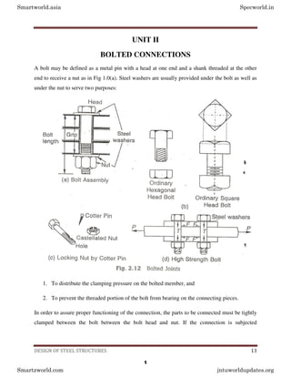
  • 1. DESIGN OF STEEL STRUCTURES 13 UNIT II BOLTED CONNECTIONS A bolt may be defined as a metal pin with a head at one end and a shank threaded at the other end to receive a nut as in Fig 1.0(a). Steel washers are usually provided under the bolt as well as under the nut to serve two purposes: 1. To distribute the clamping pressure on the bolted member, and 2. To prevent the threaded portion of the bolt from bearing on the connecting pieces. In order to assure proper functioning of the connection, the parts to be connected must be tightly clamped between the bolt between the bolt head and nut. If the connection is subjected Smartworld.asia Specworld.in Smartzworld.com jntuworldupdates.org 1
  • 2. DESIGN OF STEEL STRUCTURES 14 vibrations, the nuts must be locked in position. Bolted connections are quit similar to riveted connections in behaviour but have some distinct advantages as follows: 1. The erection of the structure can be speeded up, and 2. Less skilled persons are required. The general objections to the use of bolts are: 1. Cost of material is high: about double that of rivets. 2. The tensile strength of the bolt is reduced because of area reduction at the root of the thread and also due to stress concentration. 3. Normally these are of a loose fit excepting turned bolts and hence their strength is reduced. 4. When subjected to vibrations or shocks bolts may get loose. Uses 1. Bolts can be used for making end connections in tensions and compression member. 2. Bolts can also be used to hold down column bases in position. 3. They can be used as separators for purlins and beams in foundations, etc. Types There are several types of bolts used to connect the structural elements. Some of the bolts commonly used are: a) Unfinished bolts b) Turned bolts Smartworld.asia Specworld.in Smartzworld.com jntuworldupdates.org 2
  • 3. DESIGN OF STEEL STRUCTURES 15 c) Ribbed bolts d) High strength bolts e) Interference bolts UNFINISHED BOLTS Unfinished bolts are also called ordinary, common, rough or black bolts. There are used for light structures (purlins, bracings, etc.) under static loads. They are not recommended for connections subjected to impact load, vibrations and fatigue. Bolts are forged from low carbon rolled steel circular rods, permitting large tolerances. Ordinary structural bolts are made from mild steel with square or hexagonal head, as shown in Fig 1.0(b). Square heads cost less but hexagonal heads give a better appearance, are easier to hold by wrenches and require less turning space. The bolt hole is punched about 1.6mm more than the bolt diameter. The nuts on bolts are tightened with spud wrenches, producing little tension. Therefore, no clamping force is induced on the sections jointed. Sometimes a hole is drilled in the bolt and a cotter pin with a castellated nut is used to prevent the nut from turning on the bolt, as shown in Fig 1.0(c). the connections with unfinished bolts are designed in a similar way as all the riveted connections except that the permissible stresses are reduced to account for tolerances provide on shank and threaded portion of the bolts. The requirements regarding pitch and edge distance are same as that for rivets. The permissible stresses are as given in Table 8.1 of I.S:800-1984. TURNED BOLTS These are similar to unfinished bolts, with the differences that the shank of these bolts is formed from a hexagonal rod. The surfaces of the bolts are prepared carefully and are machined to fit in the hole. Tolerances allowed are very small. These bolts have high shear and bearing resistance as compared to unfinished bolts. However, these bolts are obsolete nowadays. The specifications for turned bolts are given in I.S:2591-1969. RIBBED BOLTS These are also called fluted bolts. The head of the bolt is like a rivet head. The threaded and nut are provided on the other end of the shank. From the shank core longitudinal ribs project making the diameter of the shank more than the diameter of the hole. These ribs cut grooves into the connected members while tightening and ensure a tight fit. These bolts have more resistance to Smartworld.asia Specworld.in Smartzworld.com jntuworldupdates.org 3
  • 4. DESIGN OF STEEL STRUCTURES 16 vibrations as compared to ordinary bolts. The permissible stresses for ribbed are same as that for rivets. HIGH STRENGTH BOLT These bolts are called friction grip bolts. These are made from bars of medium carbon steel. Their high strength is achieved through quenching and tempering processes or by alloying steel. Steel washers of hard steel or carburized steel are provided as shown in Fig1.0 (d), to evenly distribute the clamping pressure on the bolted member and to prevent the threaded portion of the bolt from bearing on the connecting pieces. If the bolts are tightened by the turn of nut method, the nut is made snug and is tightened a half turn more by hand wrenches, then the washers are not required. The vibrations and impact resistance of the joint is also improved. The nut and head of the bolts are kept sufficiently large to provide an adequate bearing area. The specifications for high strength bolts are laid in I.S:3757-1972 and I.S: 4000-1967. These bolts have a tensile strength several times that of the ordinary bolts. High strength bolts have replaced rivets and are being used in structures, such as high rise buildings, bridges, machines etc. Due to their distinct advantages and vital use, high strength bolts are discussed below in some detail. Advantages of high strength bolts High strength friction grip (HSFG) bolts have replaced the rivets because of their distinct advantages as discussed below. However, the material cost is about 50% greater than that of ordinary bolts and special workmanship is required in installing and tightening these bolts. 1. These provide a rigid joint. There is no slip between the elements connected 2. Large tensile stresses are developed in bolts, which in turn provide large clamping force to the elements connected. High frictional resistances is developed providing a high static strength the joint. 3. Because of the clamping action, load is transmitted by friction only and the bolts are not subjected to shear and bearing. Smartworld.asia Specworld.in Smartzworld.com jntuworldupdates.org 4
  • 5. DESIGN OF STEEL STRUCTURES 17 4. The frictional resistance is effective outside the hole and therefore lesser load is transmitted through the net section. Thus, the possibility of failure at the net section is minimized. 5. There are no stress concentrations in the holes; therefore, the fatigue strength is more. 6. The tension in bolts is uniform. Also the bolts are tensioned up to proof load hence; the nuts are prevented from loosening 7. Few persons are require to make the connections, thus cost is reduced. 8. Noise nuisance is not there as these bolts are tightened with wrenches. 9. The hazard of fire is not there and there is no danger of tossing of the bolt. 10. Alterations can be done easily. 11. For some strength, lesser number of bolts are required as compared to rivets which brings overall economy. Principles of high strength bolts The shank of the high strength bolts does not fully fill the hole. So shear and bearing are not the criteria for load transmission as is in the case of rivets, which fill the hole completely. The nut is tightened to develop a clamping force on the plates which is indicated as the tensile force T in the Bolt. This tension should be about 90% of proof load. When a shear load is applied to the joint no slip will occur until the shear load exceeds the frictional resistance between the elements jointed. When shear load exceeds the frictional resistance a slip occurs. On further increase of this load, the gradual slipping brings the bolt in contact with the plate edges. The horizontal frictional forces F, is induced in the joints which is equal to the tensile force T, as in Fig.1.0(d), in the bolts multiplied by the coefficient of friction. F = µT This frictional force F should exceed the applied force P on the member. Smartworld.asia Specworld.in Smartzworld.com jntuworldupdates.org 5
  • 6. DESIGN OF STEEL STRUCTURES 18 µ= Coefficient of friction or slip factor, is defined as ratio of the load per effective interface required to produce slip in a pure shear joint to the proof load induced in bolt. When the element surfaces are free from paint, dust, etc. its value is 0.45. PIN CONNECTIONS When two structural members are connected by means of a cylindrical shaped pin, the connection is called a pin connection. Pins are manufactured from mild steel bars with diameters ranging from 9 to 330 mm. Pin connections are provided when hinged joints are required, i.e., for the connection where zero moment of free rotation is desired. Introduction of a hinge simplifies the analysis by reducing indeterminacy. These also reduce the secondary stresses. These connections cannot resist longitudinal tension. For satisfactory working it is necessary to minimize the friction between the and members connected. High grade machining is done to make the pin and pin hole surface smooth and frictionless. Pins are provided in the following cases: 1. Tie rod connections water tanks and elevated bins 2. As diagonal bracing connections in beams and columns 3. Truss bridge girders 4. Hinged arches 5. Chain-link cables suspension bridges Smartworld.asia Specworld.in Smartzworld.com jntuworldupdates.org 6
  • 7. DESIGN OF STEEL STRUCTURES 19 Various types of pins used for making the connections are forged steel pin, undrilled pin and dilled pin. To make a pin connection, one end of the bar is forged like a fork and a hole is drilled in this portion. The end of the other bar to be connected is also forged and an eye is made. A hole is drilled into it in such a way that it matches with the hole on the fork end bar. The eye bar is inserted in the jaws of the fork end and a pin is placed. Both the forged ends are made octagonal for a good grip. The pin in the joint is secured by means of a cotter pin or screw, as shown in Fig. 2.13. FAILURE OF BOLTED JOINTS The bolted joint may fail in any of the following six ways, out of which some failures can be checked by adherence to the specifications of edge distance. Therefore, they are not of much importance, whereas the others require due consideration. Smartworld.asia Specworld.in Smartzworld.com jntuworldupdates.org 7
  • 8. DESIGN OF STEEL STRUCTURES 20 Shear failure of bolts (Fig. 2.3 (a)) The shear stress in the bolt may exceed the working shear stress in the bolt. Shear stresses are generated because the plates slip due to applied forces. Shear failure of plates (Fig. 2.3(b)) The internal pressure of overdriven (shank length more than the grip) bolts placed at a lesser edge distance than specified causes this failure. This can be checked by providing proper edge distance between the center of the hole and the end of the plate as specified by I.S.800. Tension or tearing failure of plates (Fig. 2.3(c)) The tensile stress in the plate at the net cross-section may exceed the working tensile stress. Tearing failure occurs when bolts are stronger than the plates. Smartworld.asia Specworld.in Smartzworld.com jntuworldupdates.org 8
  • 9. DESIGN OF STEEL STRUCTURES 21 Splitting of plates (Fig. 2.3(d)) Bolts may have been placed at a lesser edge distance than required causing the plates to split or shear out. Bearing failure of plates (Fig. 2.3(e)) The plate may be crushed when the bearing stress in the plate exceeds the working bearing stress. Bearing failure of bolts (Fig. 2.3(f)) The bolt is crushed around the half circumference. The plate may be strong in bearing and the heaviest stressed plate may press the bolt. TYPES OF RIVETED JOINTS Smartworld.asia Specworld.in Smartzworld.com jntuworldupdates.org 9
  • 10. DESIGN OF STEEL STRUCTURES 22 There are two types of riveted joints: lap joint and butt joint. Lap joint The two members to be connected are overlapped and connected together. Such a joint is called a lap joint as in Fig. (a). A single riveted lap joint and a double riveted lap joint are shown in Figs (b,c) respectively. The load in the lap joint has eccentricity, as the centre of gravity of load in one member and the centre of gravity of load in the second member are not in the same line, as shown in Fig. 2.2(d). Therefore, a couple is formed which causes undesirable bending in the connection and the rivets may fail in tension. To minimize the effect of bending in lap joints at least two rivets in a line should be provided. Also, due to the eccentricity the stresses are distributed un-evenly across the contact area between rivets and the members to be connected. This puts a limitation on the use of lap joints. Butt joint The two members to be connected are placed end to end. Additional plate/plates provided on either one or both sides, called cover plates and are connected to the main plates Smartworld.asia Specworld.in Smartzworld.com jntuworldupdates.org 10
  • 11. DESIGN OF STEEL STRUCTURES 23 as in Figs 2.2(e,h). If the cover plate is provided on one side as in Figs 2.2(f), (g), it is called a single cover butt joint but if the cover plates are provided on both the sides of main plates it is called a double cover butt joint as shown in Fig. 2.2.(i),(j). It is more desirable to provide a butt joint than a lap joint for two main reasons: In the case of double cover butt joint the total shear force to be transmitted by the members is split into two parts and the force acts on each half as shown in Fig. 2.2(k). But in the case of lap joint (Fig. 2.2(I), there is only one plane on which the force acts and therefore the shear carrying capacity of a rivet in a butt joint is double that of a rivet in a lap joint. In the case of a double cover butt joint, eccentricity of force does not exist and hence bending is eliminated, whereas it exists in the case of a lap joint. Design of Bearing Bolts Subjected to Eccentric Loading Causing Moment in the Plane Perpendicular to the Plane of Group of Bolts. Smartworld.asia Specworld.in Smartzworld.com jntuworldupdates.org 11
  • 12. DESIGN OF STEEL STRUCTURES 24 This type of connection is shown in Fig. 3.23. Referring to Fig. 3.28, let P be factored load at an eccentricity ‘e’. Then the section is subjected to a direct shear force P and moment M = Pxe. If there are ‘n’ numbers of bolts in the connection, direct design shear force on each bolt is given by, Vsb = P/n The moment causes tension in top side and compression in the bottom side. On tension side, only bolts resist load but on compression side entire contact zone between the columns and the connecting angle resist the load. Hence the neutral axis will be much below in these connections. It is assumed to lie at a height of 1/7 th of the depth of the bracket, measured from the bottom edge of the angle. The variation of the force is as shown in Fig. 3.28(c). The tensile force in a bolt Tbi is proportional to its distance yi from the line of rotation. Tbi ∝ yi = kyi, where k is constant. Smartworld.asia Specworld.in Smartzworld.com jntuworldupdates.org 12
  • 13. DESIGN OF STEEL STRUCTURES 25 . ‘. k = Tbi / yi Total moment of resistance M’ provided by bolts in tension. 2 ' ∑ ∑ = = i i bi ky y T M 2 2 ' ∑ ∑ = = i i bi i y y T y k M ∑ = i i bi y y M T 2 ' Or Total tensile force in bolts ∑ ∑ = = i i bi y y M T T 2 ' For equilibrium, Total tensile force = total compressive force ∑ ∑ = = i i y y M C T 2 ' Taking moment about neutral axis, 7 3 2 ' h C M M + =         + = ∑ ∑ i i y y h M 2 21 2 1 ' Smartworld.asia Specworld.in Smartzworld.com jntuworldupdates.org 13
  • 14. DESIGN OF STEEL STRUCTURES 26         + = ∑ ∑ i i y y h M 2 21 2 1 1 ' Tensile force Tdh in extreme bolt can be found. This equation gives the moment resisted by the bolts in tension from which the maximum tensile force in the extreme bolt Tb can be calculated. Then the design required is 0 . 1 2 2 ≤         +         dh b dh sb T T V V Steps to be followed in the design Step 1: Select nominal diameter ‘d’ of bolts. Step 2: Adopt a pitch(p) of 2.5d to 3.5d for bolts. Step 3: Bolts are to be provided in two vertical rows. Number of bolts necessary in each row is computed from the expression. ( )P V M n 2 6 = Where M is the moment on the joint and V is the design strength of bolt. Step 4: Find the direct shear and tensile forces acting on the extreme bolt. If it is HSFG bolted connection adds prying force [Ref. Fig. 3.28] to direct tension. Check whether the interaction formula is satisfied. Example 3.11 Smartworld.asia Specworld.in Smartzworld.com jntuworldupdates.org 14
  • 15. DESIGN OF STEEL STRUCTURES 27 Design a suitable bolted bracket connection of a ISHT-75 section attached to the flange of a ISHB 300 at 577N/m to carry a vertical factored load of 600 kN at an eccentricity of 300 mm. Use M24 bolts of grade 4.6 Solution: For M24 bolts of grade 4.6, D=24mm, do=27mm, fub=400N/mm2 Thickness of flange of ISHT 75 (from steel table) = 9mm For ISHB 300 @ 577 N/m, thickness of flange = 10.6mm Therefore, thickness of thinner member = 9mm Design strength of bolt in single shear =       + 2 24 4 78 . 0 0 3 400 25 . 1 1 X X π = 65192 N Design strength of bolts in bearing: Minimum edge distance e = 1.5xdo=1.5x24 = 40.5 mm Minimum pitch p =2.5d =2.5x24 = 60 mm Provide e = 50 mm and p =70mm Kb is minimum of 0 . 1 , 25 . 0 3 , 3 0 0 and f f d p d e u ub − i.e., minimum of 0 . 1 410 400 , 25 . 0 27 3 70 , 27 3 50 and X X − . ‘. Kb = 0.6412 Design strength of bolts in bearing against 9 mm thick web of Tee section Smartworld.asia Specworld.in Smartzworld.com jntuworldupdates.org 15
  • 16. DESIGN OF STEEL STRUCTURES 28 u b XdtXf Xk X 25 . 2 25 . 1 1 = 410 9 24 6142 . 0 25 . 2 25 . 1 1 X X X X X = N N 65192 109333 > = .’. Design strength of bolts V=Vdb = 65192 N Design tension capacity of bolts 10 . 1 25 . 1 90 . 0 sb yb n ub bi A f XA Xf T < = 10 . 1 24 4 240 24 4 78 . 0 25 . 1 400 90 . 0 2 2 X X X X X X Tbi π π < = = 98703N Using two rows of bolting, approximately number of bolts required in each row ( ) ( ) 87 . 10 70 65192 2 300 1000 600 6 2 6 = = = X X X X X P V M n Provide 11 bolts in each row as show in Fig h = 50+70x10=750mm h/7 = 107.14mm Smartworld.asia Specworld.in Smartzworld.com jntuworldupdates.org 16
  • 17. DESIGN OF STEEL STRUCTURES 29 i.e. neutral axis lies between 1st and 2nd bolts. .’. y of second bolt = (50+70)-107.14=12.86mm Smartworld.asia Specworld.in Smartzworld.com jntuworldupdates.org 17
  • 18. DESIGN OF STEEL STRUCTURES 30 ∑ = mm X y 6 . 3278 2 .'. 2 2 1479142 2 .'.∑ = mm X y Total moment resisted by bolts in tension       + =         + = ∑ ∑ 1479142 2 6 . 3278 2 21 750 2 1 300 1000 600 21 2 1 1 ' 2 X X X X X y y h M i i =155397179N-mm Tensile force in extreme bolt due to bending moment N X X y y M T i i b 33769 86 . 642 1479142 2 155397179 ' 2 = = = ∑ Direct shear force N X X Vsb 27273 11 2 1000 600 = = Check by interaction formula = 2 2         +         db b db sb T T V V 2 2 98703 33769 65192 27273       +       = = 0.292 < 1.0 Hence the bots are safe. Provide bots as shown in Fig. 3.29. SHEAR CAPACITY OF HSFG BOLTS Smartworld.asia Specworld.in Smartzworld.com jntuworldupdates.org 18
  • 19. DESIGN OF STEEL STRUCTURES 31 As stated in Fig, these are the bolts made of high tensile steel which are pretensioned and then provided with nuts. The nuts are clamped also. Hence resistance to shear force is mainly by friction. There are two types of HSFG bolts. They are parallel shank and waisted shank type. Parallel shank type HSFG bolts are designed for no-slip at serviceability loads. Hence they slip at higher loads and slip into bearing at ultimate loads. Hence such bolts are checked for their bearing strength at ultimate load. Waisted shank HSFG bolts are designed for no slip even at ultimate load and hence there is no need to check for their bearing strength. Vnsf = µf ne Kh F0 Where, µf = Co-efficient of friction (Called slip factor) as specified in Table 3.1. ne = number of effective interfaces offering frictional resistance to this slip. [Note: ne = 1 for lap joints and 2 for double cover butt joints] Kh = 1.0 for fasteners in clearance holes = 0.85 for fasteners in oversized and short slotted holes and for long slotted holes located perpendicular to the slot. =0.70 for fasteners in long slotted holes loaded parallel to the slot. F0 = Minimum bolt tension at installation and may be taken as Anb f0 Anb = net area of the bolt at threads       = 2 4 78 . 0 d π f0 = Proof stress = 0.70 fub Smartworld.asia Specworld.in Smartzworld.com jntuworldupdates.org 19
  • 20. DESIGN OF STEEL STRUCTURES 32 The slip resistance should be taken as Vsf = Vnsf /1.10 Where, =1.10, if the slip resistance is designed at service load (Parallel shank HSFG) =1.25, if the slip resistance is designed at ultimate load (Waisted shank HSFG). It may be noted that the reduction factors specified (Fig. 3.11) for bearing bolts hold good for HSFG bolts also. For commonly used HSFG bolts (Grade 8.8), yield stress fyb =640 Mpa and ultimate stress fub =800 N/mm2 Example 3.12 Determine the shear capacity of bolts used in connecting two plates as shown in Fig.3.30 1. Slip resistance is designated at service load Smartworld.asia Specworld.in Smartzworld.com jntuworldupdates.org 20
  • 21. DESIGN OF STEEL STRUCTURES 33 2. Slip resistance is designated at ultimate load Given: HSFG bolts of grade 8.8 are used. Fasteners are in clearance holes Coefficient of friction = 0.3 Solution: For HSFG bolts of grade 8.8, For fasteners in clearance holes Kh = 1.0 Coefficient of friction µf =0.3 .’. Nominal shear capacity of a bolt Vnsf = µf nc Kh F0 Where F0 = 0.7 fub Anb       = 2 20 4 78 . 0 800 7 . 0 X X X X π ne=2, since it is double cover butt joint (i) Design capacity of one bolt, if slip resistance is designated at service load Vnsf = 0.3 x 2 x1.0 x137225 = 82335 N = 82335/1.1 =74850 N Therefore design capacity of joint = 6 x 74850, since 6 bolts are used = 449099 N = 449.099 kN (ii) Design capacity of one bolt, if the slip resistance is designated at ultimate load Smartworld.asia Specworld.in Smartzworld.com jntuworldupdates.org 21
  • 22. DESIGN OF STEEL STRUCTURES 34 = 82335/1.25 =65868 N Therefore design capacity of joint = 6 x 65868, since 6 bolts are used = 395208 N = 395.208 kN In case (i), bearing strength at ultimate load should be checked. If it is low that will be the governing factor. TENSION RESISTANCE OF HSFG BOLTS The expression for nominal tension strength of HSFG bolts is also as that for bearing bolts. i.e, m mb sb yb n ub nf A f XA Xf T γ γ ≤ = 9 . 0 m sb yb mb n ub df A f A f T γ γ ≤ = 9 . 0 Where An = net tensile area as specified in various parts of IS 1367, it may be taken as the area at the root of the thread       = 2 4 78 . 0 d π Asb = shanke area. γmb = 1.25, γm = 1.1 fub for bolts of grade 8.8 is 800 MPa and fyb = 640 MPa. Smartworld.asia Specworld.in Smartzworld.com jntuworldupdates.org 22
  • 23. DESIGN OF STEEL STRUCTURES 35 INTERACTION FORMULA FOR COMBINED SHEAR AND TENSION If bolts are under combined action of shear and axial tension, the interaction formula to be satisfied is 0 . 1 2 2 ≤         +         df f df sf T T V V PRYING FORCES In the design of HSFG bolts subjected to tensile forces, an additional force, called as prying force Q is to be considered. These additional forces are mainly due to flexibility of connected plates. Consider the connection of a T-section to a plate as shown in Fig 3.31, subject to tensile force 2Te. As tensile force acts, the flange of T-section bends in the middle portion and presses connecting plates near bolts. It gives rise to additional contact forces known as prying forces. During late 80s and early 90s lot of research works were published regarding assessing prying force. IS 800- 2007 has accepted the following expression         − = y c e e c y l l t b f T l l Q 2 4 0 27 2 βη Where Smartworld.asia Specworld.in Smartzworld.com jntuworldupdates.org 23
  • 24. DESIGN OF STEEL STRUCTURES 36 Q = prying force 2Te = total applied tensile force ly = distance from the bolt centre line to the toe of the fillet weld or to half the root radius for a rolled section. lc = distance between prying forces and bolt centre line and is the minimum of either the end distance or the value given by: y c f f t l 0 1 . 1 β = β = 2 for non-pretensioned bolts and for pretensioned bolts η = 1.5 be = effective width of flange per pair of bolts. f0 = Proof stress in consistent units t = thickness of end plate. Note that prying forces do not develop in case of ordinary bolts, since when bolt failure takes place contact between the two connecting plates is lost (Ref. Fig. 3.32). Smartworld.asia Specworld.in Smartzworld.com jntuworldupdates.org 24
  • 25. DESIGN OF STEEL STRUCTURES 37 Example The joint shown in fig has to carry a factored load of 180kN. End plate used is of size 160 mm x 40 mm x 16 mm. The bolts used are M20 HSFG of grade 8.8. Check whether the design is safe. Solution: Assuming 8 mm weld and edge distance 40mm, ly = 160/2 – 8-8-40 = 24 mm y c f f t l 0 1 . 1 β = For plates, f0 = 0.7 fu, fu =410 MPa and fy =250 MPa < = = 86 . 18 250 410 7 . 0 1 16 1 . 1 X X X lc < Edge distance lc = 18.86 mm Prying force is given by,         − = y c e e c y l l t b f T l l Q 2 4 0 27 2 βη Smartworld.asia Specworld.in Smartzworld.com jntuworldupdates.org 25
  • 26. DESIGN OF STEEL STRUCTURES 38 β = 1.0, for pretensioned bolts. η = 1.5 be = 140mm, t = 16mm. f0 = 0.7 x 800 = 560MPa         − = 2 4 24 86 . 18 27 16 140 560 5 . 1 1 90000 86 . 18 2 24 X X X X X X X Q = 40545 N Therefore tension to be resisted by the bolt T = T+Q = 90000 + 40545 =130545 N Tension capacity of the bolt 25 . 1 9 . 0 ub ub A f = 25 . 1 20 4 78 . 0 800 9 . 0 2 X X X X π = =141145 N > 130545 N Hence the design is safe. Smartworld.asia Specworld.in Smartzworld.com jntuworldupdates.org 26