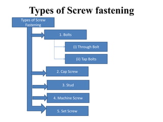
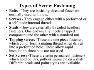
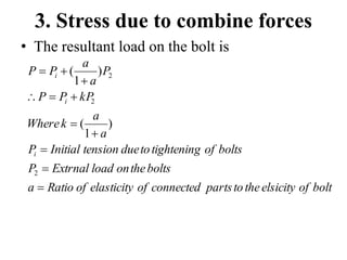
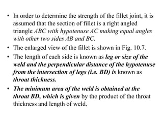
The document discusses the design of various types of screw fasteners. It describes screw threads as helical grooves cut into cylindrical surfaces. Screw joints are commonly used for assembly and have advantages of being convenient to assemble/disassemble, reliable, and inexpensive due to standardization. The main types of screw fasteners are bolts, screws, studs, tapping screws, and set screws. Stresses in screw joints include tension, torsional shear, shear across threads, crushing stress, and bending stress. Screw joints are also subjected to stresses from initial tightening and external loads. Design considerations are discussed for bolted joints under eccentric loading parallel or perpendicular to the bolt axis.

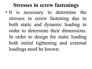
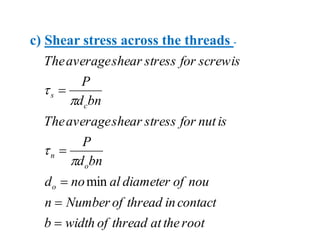
![b) Shear Stress in bolt –
n
d
P
o
s
2
4
c) Combine tension and shear stress
]
4
[
2
1
]
4
[
2
1
)
(
2
2
max
2
2
max
t
t
t
t
stress
shear
Maximum
sress
tensile
principal
Maximum](https://image.slidesharecdn.com/designoffasteners-240209122046-024c01b8/85/Design-of-Fasteners-pdf-25-320.jpg)
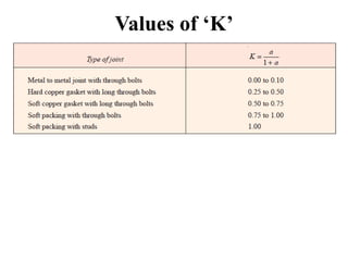

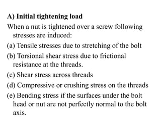
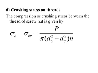
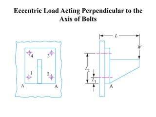
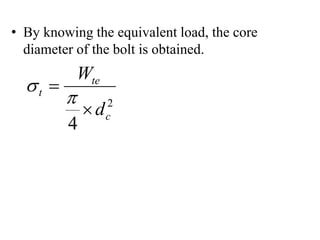
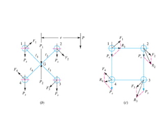
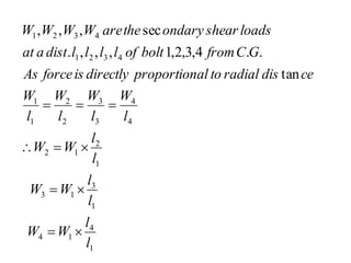
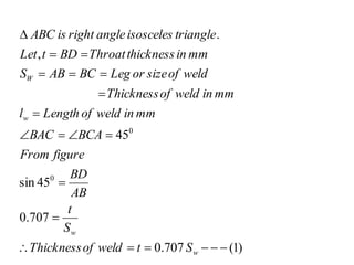
![• Similarly, the moment of load W2 about tilting
edge
)
2
(
,
tan
)
1
(
]
[
2 2
2
2
1
2
1
2
2
2
2
2
2
2
WL
M
edge
tilting
about
L
ce
dis
a
at
W
load
the
of
moment
The
wL
wL
M
M
M
edge
tilting
about
load
of
moment
Total
wL
L
wL
L
W
M
Equating equation (1) and (2)](https://image.slidesharecdn.com/designoffasteners-240209122046-024c01b8/85/Design-of-Fasteners-pdf-36-320.jpg)
![2
2
2
2
2
1
2
2
2
2
2
2
2
2
2
1
2
2
2
1
2
2
2
1
4
]
[
2
tan
tan
]
[
2
]
[
2
]
[
2
c
t
t
t
td
t
Total
t
d
W
stress
tensile
to
subjected
bolt
the
As
W
W
W
W
bolts
loaded
heavily
most
on
load
Total
L
L
L
L
W
wL
W
W
L
ce
dis
at
bolt
each
on
load
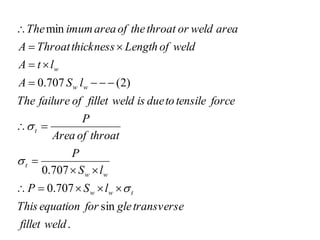
Tensile
loaded
heavily
most
are
L
ce
dis
at
bolts
The
L
L
WL
w
L
L
w
wL
wL
WL
](https://image.slidesharecdn.com/designoffasteners-240209122046-024c01b8/85/Design-of-Fasteners-pdf-37-320.jpg)
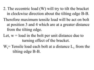
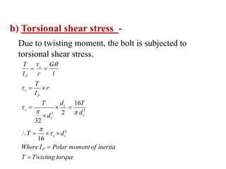
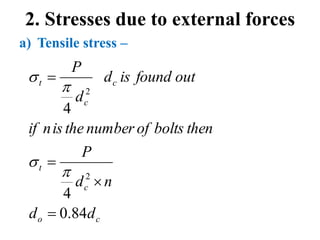
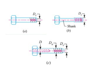
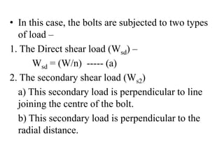
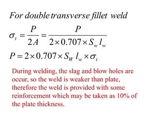
![• Similarly Wt will be the tensile load each bolt at
a distance L2 from the tilting edge B-B.
)
5
(
]
[
2
2
2
)
4
(
2
,
.
2
2
2
1
2
2
2
1
2
1
2
2
2
2
2
2
2
2
2
2
2
2
L
L
w
M
L
w
L
w
M
M
M
M
is
edge
tilting
about
moment
Total
L
w
M
hence
L
dist
a
at
are
bolts
two
the
As
L
w
L
W
M
edge
tilting
about
W
load
the
of
Moment
L
w
W
t
t
t](https://image.slidesharecdn.com/designoffasteners-240209122046-024c01b8/85/Design-of-Fasteners-pdf-42-320.jpg)
![)
7
(
]
[
2
]
[
2
.
.
4
&
3
max
]
[
2
]
[
2
6
&
5
)
6
(
.
)
(
2
2
2
1
2
2
2
2
2
2
1
2
2
2
2
2
2
1
2
2
2
1
L
L
L
L
W
W
L
L
L
L
W
L
w
W
edge
tilting
from
L
dist
a
at
situated
are
which
bolt
a
in
willbe
load
tensile
imum
The
L
L
L
W
w
L
L
w
L
W
equation
Equating
L
W
M
is
L
dist
a
at
W
load
to
due
bracket
of
moment
The
t
t](https://image.slidesharecdn.com/designoffasteners-240209122046-024c01b8/85/Design-of-Fasteners-pdf-43-320.jpg)
![]
4
[
2
1
)
(
]
4
[
2
1
)
(
.
2
2
2
2
2
2
2
s
t
se
se
s
t
t
te
te
W
W
W
W
load
shear
Equivalent
And
W
W
W
W
W
load
tensile
Equivalent
load
shear
as
well
as
tensile
combile
to
subjected
are
bolts
the
As
](https://image.slidesharecdn.com/designoffasteners-240209122046-024c01b8/85/Design-of-Fasteners-pdf-44-320.jpg)
![• Sum of turning moment due to eccentric load and
internal resisting moment of the bolt must be
zero.
calculated
is
W
b
equation
From
b
l
l
l
l
l
W
l
l
l
W
l
l
l
W
l
l
l
W
l
W
l
W
l
W
l
W
l
W
e
W
1
2
4
2
3
2
2
2
1
1
1
4
1
4
1
3
1
3
1
2
1
2
1
1
1
4
4
3
3
2
2
1
1
'
'
)
(
]
[
)
(
)
(
)
(
](https://image.slidesharecdn.com/designoffasteners-240209122046-024c01b8/85/Design-of-Fasteners-pdf-50-320.jpg)
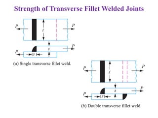
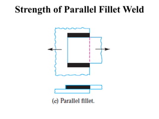
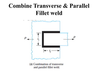
![• In combination of parallel and transverse fillet
weld, the weld is subjected to tensile stress and
shear stress due to axial force.
]
707
.
0
2
[
]
707
.
0
[
)
2
(
707
.
0
2
)
1
(
707
.
0
2
1
2
1
s
w
w
t
w
w
t
s
w
w
t
w
w
l
S
l
S
P
is
weld
of
strength
Total
l
S
P
weld
fillet
parallel
For
l
S
P
weld
fillet
transverse
For
](https://image.slidesharecdn.com/designoffasteners-240209122046-024c01b8/85/Design-of-Fasteners-pdf-72-320.jpg)


![ME 312 Mechanical Machine Design [Screws, Bolts, Nuts]](https://cdn.slidesharecdn.com/ss_thumbnails/me312-dsulec10-screws-170213050612-thumbnail.jpg?width=640&height=640&fit=bounds)


