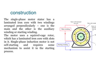
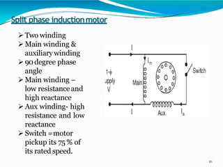
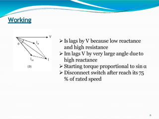
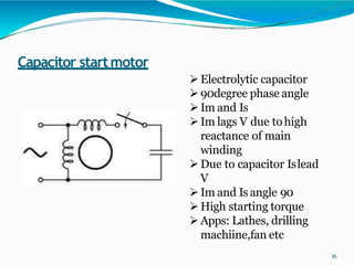
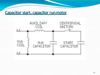
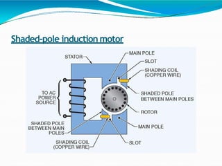
single-phase induction machine
INTRODUCTION
The single-phase induction machine is the most frequently
used motor for refrigerators, washing machines, clocks,
drills, compressors, pumps, and so forth.
 The single-phase motor stator has a laminated iron core
with two windings arranged perpendicularly. One is the
main and the other is the auxiliary winding or starting
winding.
construction
The single-phase motor stator has a
laminated iron core with two windings
arranged perpendicularly – one is the
main and the other is the auxiliary
winding or starting winding.
The motor uses a squirrel-cage rotor,
which has a laminated iron core with slots
in it. Single-phase induction motor is not
self-starting and requires some
mechanism to assist it in the starting
process.
Stator with laminated
iron core Slots with windin
Ba
R
ci
Starting winding
+
_
Main winding
Rotor wit
laminate
iron core
+
_
Operatingprinciple
operation can be
The single-phase induction motor
described by two methods:
–Double revolving field theory; and
–Cross-field theory.
 Double revolving theory is perhaps the easier of the two
Double revolving field theory
A single-phase ac current supplies the main windingthat
produces a pulsating magnetic field.
 Mathematically, the pulsating field could be divided into
two fields, which are rotating in opposite directions.
 The interaction between the fields and the current induced
in the rotor bars generates opposing torque.
DOUBLE-FIELD REVOLVING
THEORY
6
Electrical Machines
Resultant
φ𝑚
cos2Ɵ
flux φr =2 x = φ
2 2 𝑚cosƟ
5
9/21/2022 8
7.6 Single Phase Induction Motor
Double revolving field theory
The pulsating filed is divided a forward and
reverse rotating field
Motor is started in the direction of forward
rotating field this generates small (0.5%)
positive slip
Reverse rotating field generates a larger (1.95%)
negative slip
sy
m
sy
pos n
n
n
s )
( 

sy
m
sy
neg n
n
n
s )
( 

9
Single Phase Induction Motor
7.6.1 Double revolving field theory
The three-phase induction motor starting torque inversely
depends on the slip
This implies that a small positive slip (0.01–0.03)
generates larger torque than a larger negative slip
(1.95–1.99)
This torque difference drives the motor continues to
rotate in a forward direction without any external
torque.
Tm_start s
( )
3 Irot_t s
( )
 2

Rrot_t
s

2 
 nsy


9/21/2022
7.6 Single Phase Induction Motor
Double revolving field theory
Each of the rotating fields induces a voltage in
the rotor, which drives current and
produces torque.
An equivalent circuit, similar to the equivalent
circuit of a three phase motor, can represent
each field
The parameters of the two circuits are the same
with the exception of the slip.
9/21/2022 11
7.6 Single Phase Induction Motor
7.6.1 Double revolving field theory
The two equivalent circuits are connected in
series.
Figure 7.44 shows the equivalent circuit of a
single-phase motor in running condition.
The current, power and torque can be calculated
from the combined equivalent circuit using
the Ohm Law
9/21/2022 12
7.6 Single Phase Induction
Motor
Forward
rotating field
Xsta/2
Vsta
Ista
Rrot(1-spos)/(2spos)
Rsta/2
Rc/2 Xm/2
Xrot/2 Rrot/2
Reverse
rotating field
Xsta/2
Rrot
(1-sneg
)/(2sneg
)
Rsta/2
Rc
/2 Xm
/2
Xrot/2 Rrot/2
Ipos
Ineg
Figure 7.44 Equivalent circuit of a single-phase motor in running condition.
6
DOUBLE-FIELD REVOLVING
THEORY
The torque–slip curve is shown below
14
Electrical Machines
Startingtorque
zero of the
 The single-phase motor starting torque is
pulsating single-phase magnetic flux.
 The starting of the motor requires the generation of a
rotating magnetic flux similar to the rotating flux in a
three-phase motor.
 Two perpendicular coils that have currents 90° outof-phase
can generate the necessary rotating magnetic fields which
start the motor.
 Therefore, single-phase motors are built with two
perpendicular windings.
 The phase shift is achieved byconnecting
–a resistance,
–an inductance, or
–a capacitance in series with the startingwinding.
 Most frequently used is a capacitor to generate the starting
torque.
 Single-phase induction motors are classified and named
according to the method employed to make them self-starting.
(1) Split-phase induction motor :( started by two phase motor
action through the use of an auxiliary or startingwinding)
(2) Capacitor motors :( started by two phase motor action
through the use of an auxiliary and acapacitor)
(i) Capacitor-start induction run motor
(ii) Capacitor run induction motor
(iii) Capacitor-start and Capacitor run induction motor
(3) Shaded-pole induction motor :(started by the motion of the
magnetic field produced by means of shading coil around
A portion of the pole structure)
Split phase inductionmotor
10
Two winding
Main winding &
auxiliary winding
90degree phase
angle
Main winding –
low resistanceand
high reactance
Aux winding- high
resistance and low
reactance
Switch =motor
pickup its 75 % of
its rated speed.
Working
11
Islags by V because low reactance
and high resistance
Im lags V by very large angle dueto
high reactance
Starting torque proportional to sin α
Disconnect switch after reach its 75
% of rated speed
Centrifugal switch-operation
 It is connected in series with the auxiliary winding and
mounted on the rotor shaft. When the motor started and
reaches 75% of synchronous speed, CFS is mechanically
opened and in running condition auxiliary winding
remains cutout from thecircuit.
 Therefore, the motor runs only with mainwinding.
Characteristics
1.Starting torque –1.5times to 2times the full loadtorque.
2. Starting current –6 to 8times the full load current.
3. Operating power factor –0.55to .65.
4.Efficiency –60-65% 5.Power
rating-(1/20 to 1/2kW)
6. Speed range- 2875rpm to 700rpm
Applications
 It has low starting current and moderate starting torque. It
is used for easily started loads and typical applications
include fans, saws, washing machines, grinders, blowers
centrifugal pumps, oil burners, domestic refrigerators etc.
Capacitor inductionmotor
1. Capacitor start motor
2. Permanent capacitor motor
3. Capacitor start capacitor runmotor
15
Capacitor startmotor
16
Electrolytic capacitor
90degree phase angle
Im and Is
Im lags V due tohigh
reactance of main
winding
Due to capacitor Islead
V
Im and Isangle 90
High starting torque
Apps: Lathes, drilling
machiine,fan etc
Characteristics
1.Starting torque- 3.5to 4.5 times the
full load torque
2. α-varies from 30˚to 80˚-Starting
torque can be improved
3. Power factor varies from 0.65 to 0.75
4. Efficiency– 65 to 70%
5. Power rating –1/10to 3/4kW
Requirements of capacitor
 Electrolytic capacitors are used as starting capacitors ,value
around 50μFto a few hundred micro-farads.
 Capacitor designed for extremely short time duty service
and is guaranteed for not more than 20 periods of
operation/hr, each period not to exceed 3seconds.
Applications
 This motor has high starting torque and therefore is used
for hard start loads such as pumps, compressors,
refrigeration units, conveyors, certain machine tools etc.
Capacitor start, capacitor runmotor
20
Characteristics
1.Starting torque –3to 3.5times the full load torque.
2. Efficiency –60%approx.
3. Power factor-0.9 approx.
4. Power rating- 1/8to 3/4HP
5.Pull out torque- up to 260%of
rated torque
Applications
 It combines the advantages of capacitor start and
permanent-capacitors and is used for hard to start loads
such as compressors, refrigerators, pumps, conveyors etc.
 These motors are often employed requiring aquite
operating motor such as in hospitals, studios.
Shaded-pole induction motor
Theory of operation
 Small motors requiring only small starting torque may be
made self-starting by using low resistance copper bands
called shading bands.
 The emf induced in the shading band causes a current to
flow in the band. This current opposes the change of flux
to which it is due and thus there is a time lag between the
fluxes in the shaded and unshaded portion of the pole.
 The flux in the shaded portion of the pole lags the flux in
the other portion. The results is like a rotating field moving
in the direction from the unshaded to the shaded portion
of the pole and a starting torque isproduced.
Characteristics
1.Low starting torque –0.4to 0.8times the full load torque.
2. Efficiency-35% approx.
3. Powerfactor-0.45 approx.
4. Pull out torque- 15%of full load torque.
5.Power rating-1/300 to 1/20HP (2.5W to
40W)
Applications
 Because of their poor starting torque, low power factor and
poor efficiency such motors are only suitable for low power
applications such as for toys, portable fans , electric clocks,
hair dryers, slide projectors, humidifiers, small business
machines such as photo copying machines, vending
machines, advertising displays etc.
single phase induction motor.pptx

single phase induction motor.pptx

  • 1.
  • 2.
    INTRODUCTION The single-phase inductionmachine is the most frequently used motor for refrigerators, washing machines, clocks, drills, compressors, pumps, and so forth.  The single-phase motor stator has a laminated iron core with two windings arranged perpendicularly. One is the main and the other is the auxiliary winding or starting winding.
  • 3.
    construction The single-phase motorstator has a laminated iron core with two windings arranged perpendicularly – one is the main and the other is the auxiliary winding or starting winding. The motor uses a squirrel-cage rotor, which has a laminated iron core with slots in it. Single-phase induction motor is not self-starting and requires some mechanism to assist it in the starting process. Stator with laminated iron core Slots with windin Ba R ci Starting winding + _ Main winding Rotor wit laminate iron core + _
  • 4.
    Operatingprinciple operation can be Thesingle-phase induction motor described by two methods: –Double revolving field theory; and –Cross-field theory.  Double revolving theory is perhaps the easier of the two
  • 5.
    Double revolving fieldtheory A single-phase ac current supplies the main windingthat produces a pulsating magnetic field.  Mathematically, the pulsating field could be divided into two fields, which are rotating in opposite directions.  The interaction between the fields and the current induced in the rotor bars generates opposing torque.
  • 6.
  • 7.
  • 8.
    9/21/2022 8 7.6 SinglePhase Induction Motor Double revolving field theory The pulsating filed is divided a forward and reverse rotating field Motor is started in the direction of forward rotating field this generates small (0.5%) positive slip Reverse rotating field generates a larger (1.95%) negative slip sy m sy pos n n n s ) (   sy m sy neg n n n s ) (  
  • 9.
    9 Single Phase InductionMotor 7.6.1 Double revolving field theory The three-phase induction motor starting torque inversely depends on the slip This implies that a small positive slip (0.01–0.03) generates larger torque than a larger negative slip (1.95–1.99) This torque difference drives the motor continues to rotate in a forward direction without any external torque. Tm_start s ( ) 3 Irot_t s ( )  2  Rrot_t s  2   nsy  
  • 10.
    9/21/2022 7.6 Single PhaseInduction Motor Double revolving field theory Each of the rotating fields induces a voltage in the rotor, which drives current and produces torque. An equivalent circuit, similar to the equivalent circuit of a three phase motor, can represent each field The parameters of the two circuits are the same with the exception of the slip.
  • 11.
    9/21/2022 11 7.6 SinglePhase Induction Motor 7.6.1 Double revolving field theory The two equivalent circuits are connected in series. Figure 7.44 shows the equivalent circuit of a single-phase motor in running condition. The current, power and torque can be calculated from the combined equivalent circuit using the Ohm Law
  • 12.
    9/21/2022 12 7.6 SinglePhase Induction Motor Forward rotating field Xsta/2 Vsta Ista Rrot(1-spos)/(2spos) Rsta/2 Rc/2 Xm/2 Xrot/2 Rrot/2 Reverse rotating field Xsta/2 Rrot (1-sneg )/(2sneg ) Rsta/2 Rc /2 Xm /2 Xrot/2 Rrot/2 Ipos Ineg Figure 7.44 Equivalent circuit of a single-phase motor in running condition.
  • 13.
  • 14.
    DOUBLE-FIELD REVOLVING THEORY The torque–slipcurve is shown below 14 Electrical Machines
  • 15.
    Startingtorque zero of the The single-phase motor starting torque is pulsating single-phase magnetic flux.  The starting of the motor requires the generation of a rotating magnetic flux similar to the rotating flux in a three-phase motor.  Two perpendicular coils that have currents 90° outof-phase can generate the necessary rotating magnetic fields which start the motor.  Therefore, single-phase motors are built with two perpendicular windings.
  • 16.
     The phaseshift is achieved byconnecting –a resistance, –an inductance, or –a capacitance in series with the startingwinding.  Most frequently used is a capacitor to generate the starting torque.
  • 17.
     Single-phase inductionmotors are classified and named according to the method employed to make them self-starting. (1) Split-phase induction motor :( started by two phase motor action through the use of an auxiliary or startingwinding) (2) Capacitor motors :( started by two phase motor action through the use of an auxiliary and acapacitor) (i) Capacitor-start induction run motor (ii) Capacitor run induction motor (iii) Capacitor-start and Capacitor run induction motor (3) Shaded-pole induction motor :(started by the motion of the magnetic field produced by means of shading coil around A portion of the pole structure)
  • 18.
    Split phase inductionmotor 10 Twowinding Main winding & auxiliary winding 90degree phase angle Main winding – low resistanceand high reactance Aux winding- high resistance and low reactance Switch =motor pickup its 75 % of its rated speed.
  • 19.
    Working 11 Islags by Vbecause low reactance and high resistance Im lags V by very large angle dueto high reactance Starting torque proportional to sin α Disconnect switch after reach its 75 % of rated speed
  • 20.
    Centrifugal switch-operation  Itis connected in series with the auxiliary winding and mounted on the rotor shaft. When the motor started and reaches 75% of synchronous speed, CFS is mechanically opened and in running condition auxiliary winding remains cutout from thecircuit.  Therefore, the motor runs only with mainwinding.
  • 21.
    Characteristics 1.Starting torque –1.5timesto 2times the full loadtorque. 2. Starting current –6 to 8times the full load current. 3. Operating power factor –0.55to .65. 4.Efficiency –60-65% 5.Power rating-(1/20 to 1/2kW) 6. Speed range- 2875rpm to 700rpm
  • 22.
    Applications  It haslow starting current and moderate starting torque. It is used for easily started loads and typical applications include fans, saws, washing machines, grinders, blowers centrifugal pumps, oil burners, domestic refrigerators etc.
  • 23.
    Capacitor inductionmotor 1. Capacitorstart motor 2. Permanent capacitor motor 3. Capacitor start capacitor runmotor 15
  • 24.
    Capacitor startmotor 16 Electrolytic capacitor 90degreephase angle Im and Is Im lags V due tohigh reactance of main winding Due to capacitor Islead V Im and Isangle 90 High starting torque Apps: Lathes, drilling machiine,fan etc
  • 25.
    Characteristics 1.Starting torque- 3.5to4.5 times the full load torque 2. α-varies from 30˚to 80˚-Starting torque can be improved 3. Power factor varies from 0.65 to 0.75 4. Efficiency– 65 to 70% 5. Power rating –1/10to 3/4kW
  • 26.
    Requirements of capacitor Electrolytic capacitors are used as starting capacitors ,value around 50μFto a few hundred micro-farads.  Capacitor designed for extremely short time duty service and is guaranteed for not more than 20 periods of operation/hr, each period not to exceed 3seconds.
  • 27.
    Applications  This motorhas high starting torque and therefore is used for hard start loads such as pumps, compressors, refrigeration units, conveyors, certain machine tools etc.
  • 28.
  • 29.
    Characteristics 1.Starting torque –3to3.5times the full load torque. 2. Efficiency –60%approx. 3. Power factor-0.9 approx. 4. Power rating- 1/8to 3/4HP 5.Pull out torque- up to 260%of rated torque
  • 30.
    Applications  It combinesthe advantages of capacitor start and permanent-capacitors and is used for hard to start loads such as compressors, refrigerators, pumps, conveyors etc.  These motors are often employed requiring aquite operating motor such as in hospitals, studios.
  • 31.
  • 32.
    Theory of operation Small motors requiring only small starting torque may be made self-starting by using low resistance copper bands called shading bands.  The emf induced in the shading band causes a current to flow in the band. This current opposes the change of flux to which it is due and thus there is a time lag between the fluxes in the shaded and unshaded portion of the pole.  The flux in the shaded portion of the pole lags the flux in the other portion. The results is like a rotating field moving in the direction from the unshaded to the shaded portion of the pole and a starting torque isproduced.
  • 33.
    Characteristics 1.Low starting torque–0.4to 0.8times the full load torque. 2. Efficiency-35% approx. 3. Powerfactor-0.45 approx. 4. Pull out torque- 15%of full load torque. 5.Power rating-1/300 to 1/20HP (2.5W to 40W)
  • 34.
    Applications  Because oftheir poor starting torque, low power factor and poor efficiency such motors are only suitable for low power applications such as for toys, portable fans , electric clocks, hair dryers, slide projectors, humidifiers, small business machines such as photo copying machines, vending machines, advertising displays etc.