Downloaded 237 times
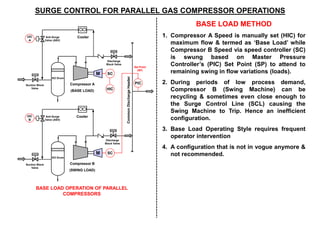
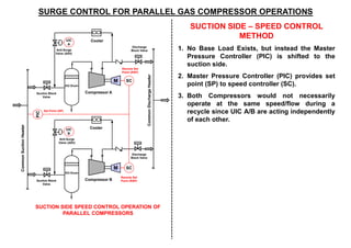

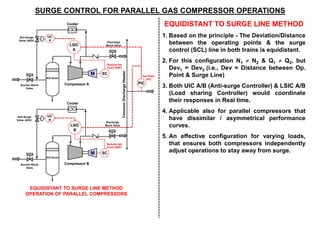

1. The document discusses different methods for controlling parallel gas compressors to prevent surge during varying load conditions. 2. The base load method operates one compressor at maximum flow while the other swings based on demand, but is inefficient and requires frequent intervention. 3. The suction side speed control and equal flow balance methods aim to control both compressors independently using a master pressure controller and additional elements, but have disadvantages related to complexity and control dynamics. 4. The equidistant to surge line method coordinates anti-surge and load sharing controllers to keep the operating points of both compressors equally distanced from the surge line to handle varying loads while preventing surge.


