Downloaded 980 times

![Centrifugal Compressor (CC) System Characteristics…
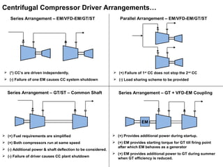
Compressor Maps dictate “behaviour” of the CC
CC Maps are a plot between Polytropic Head (or pressure ratio) vs. Volumetric Flow
Compressor to be operated always away from the surge line
Absorbed power is the least at the surge line
Range of CC operation is the enclosed region of the maps
beyond which guarantee is not provided by the manufacturer
Typically operating point is maintained within 10% to 12% of the
surge line. This can be increased on a case to case basis.
−
×
−
×
××
=
−
1
1
1
n
n
in
out
gas
inavg
p
P
P
n
n
MW
TRZ
H
ratioessure
P
P
KetemperaturInletT
onentPolytropicn
kgmolkgweightmolecularGasMW
factorilitycompressibAverageZ
KkgmolkJtConsGasR
kgFlowrateMassQ
kgkJHeadPolytropicH
in
out
in
gas
avg
in
p
Pr
,
exp
/,
/314.8,tan
sec/,
/,
=
=
=
=
=
=
=
=
inp QHPower ×=
Compressor to be operated within surge limits
Speed 4
Stone Wall
RegionSpeed 1
Speed 2
Speed 3
Actual Volumetric Flow [m3
/hr]
PolytropicHead[morkJ/kg]
Surge Line Surge Margin
Actual Volumetric Flow [m3
/hr]
Efficiency[%]
Speed 1 Speed 4
Speed 2 Speed 3](https://image.slidesharecdn.com/compressorbasics-171218195307/85/Centrifugal-Compressor-System-Design-Simulation-3-320.jpg)
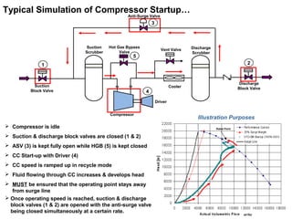

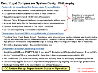


This document serves as a comprehensive beginner's guide to the design and simulation of centrifugal compressor systems, covering system characteristics, drivers, and operational scenarios including start-up and shutdown. It emphasizes the importance of maintaining operational points away from surge lines and discusses various driver options and anti-surge systems. Furthermore, it outlines factors to consider in system design, including power requirements, efficiency, and the robustness of the anti-surge mechanism.


