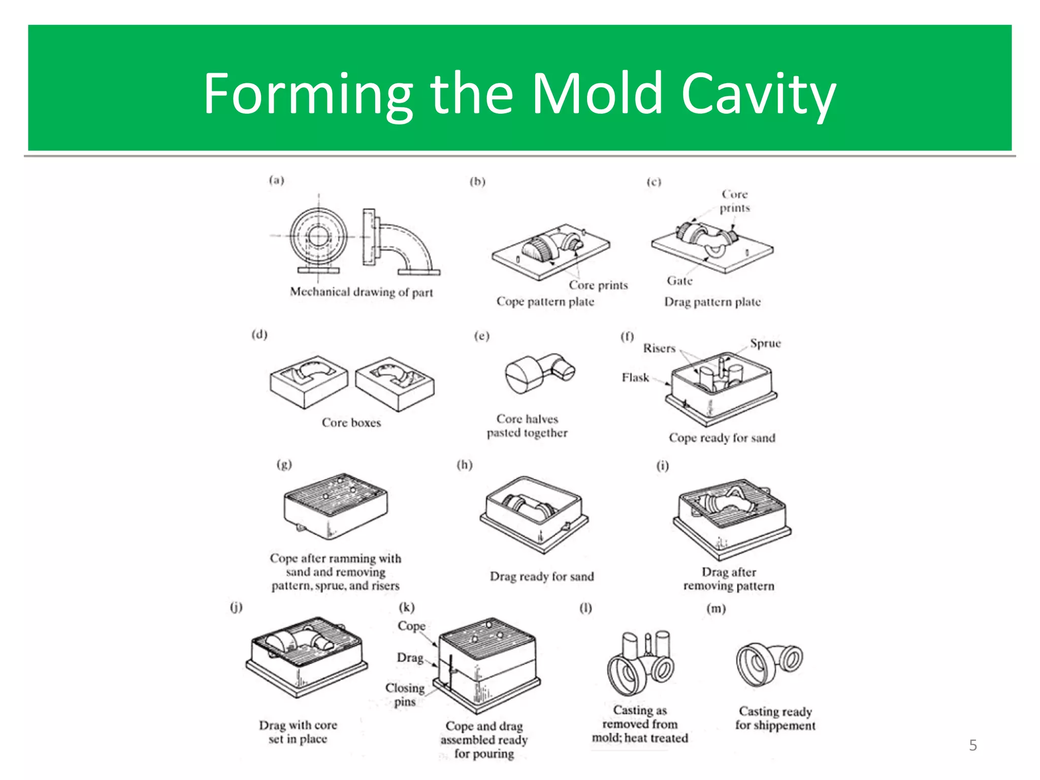
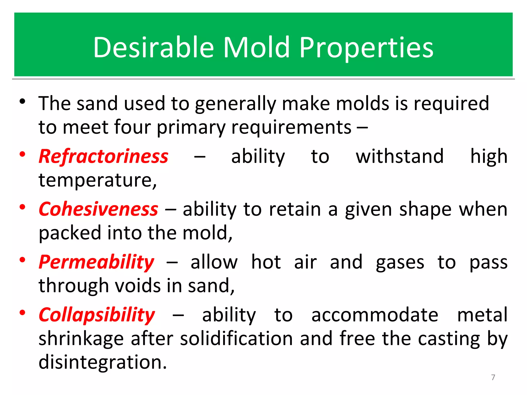
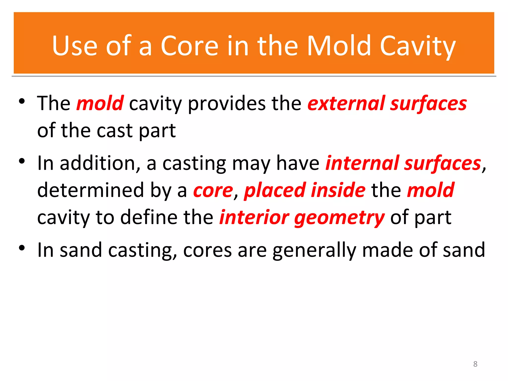
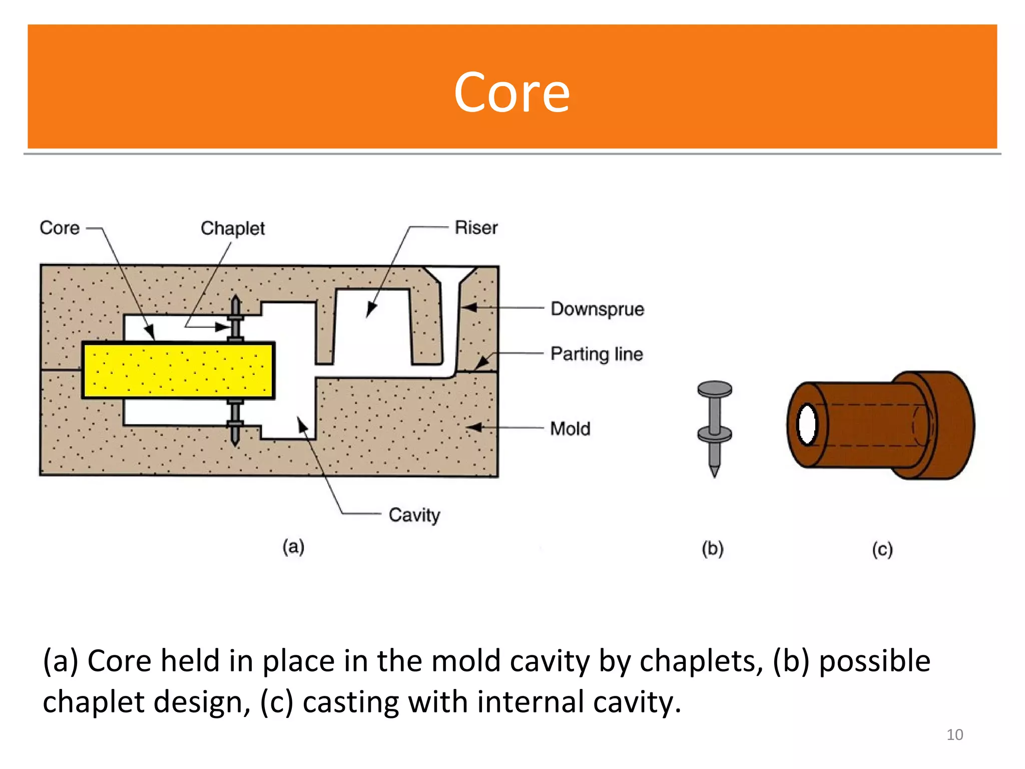
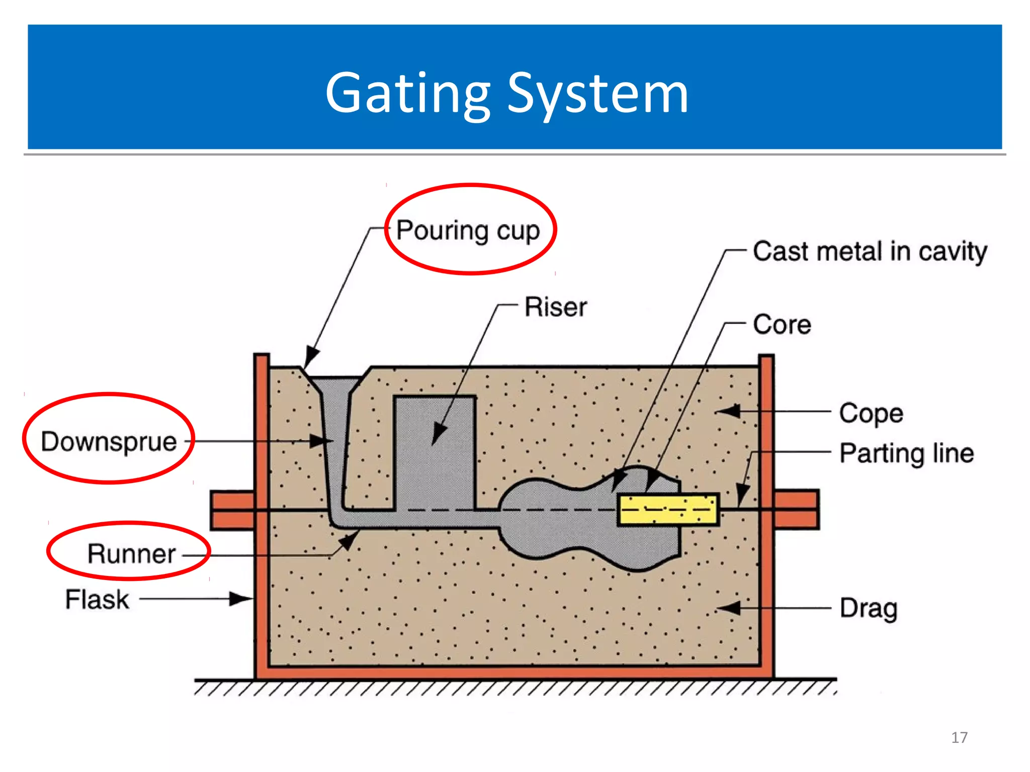
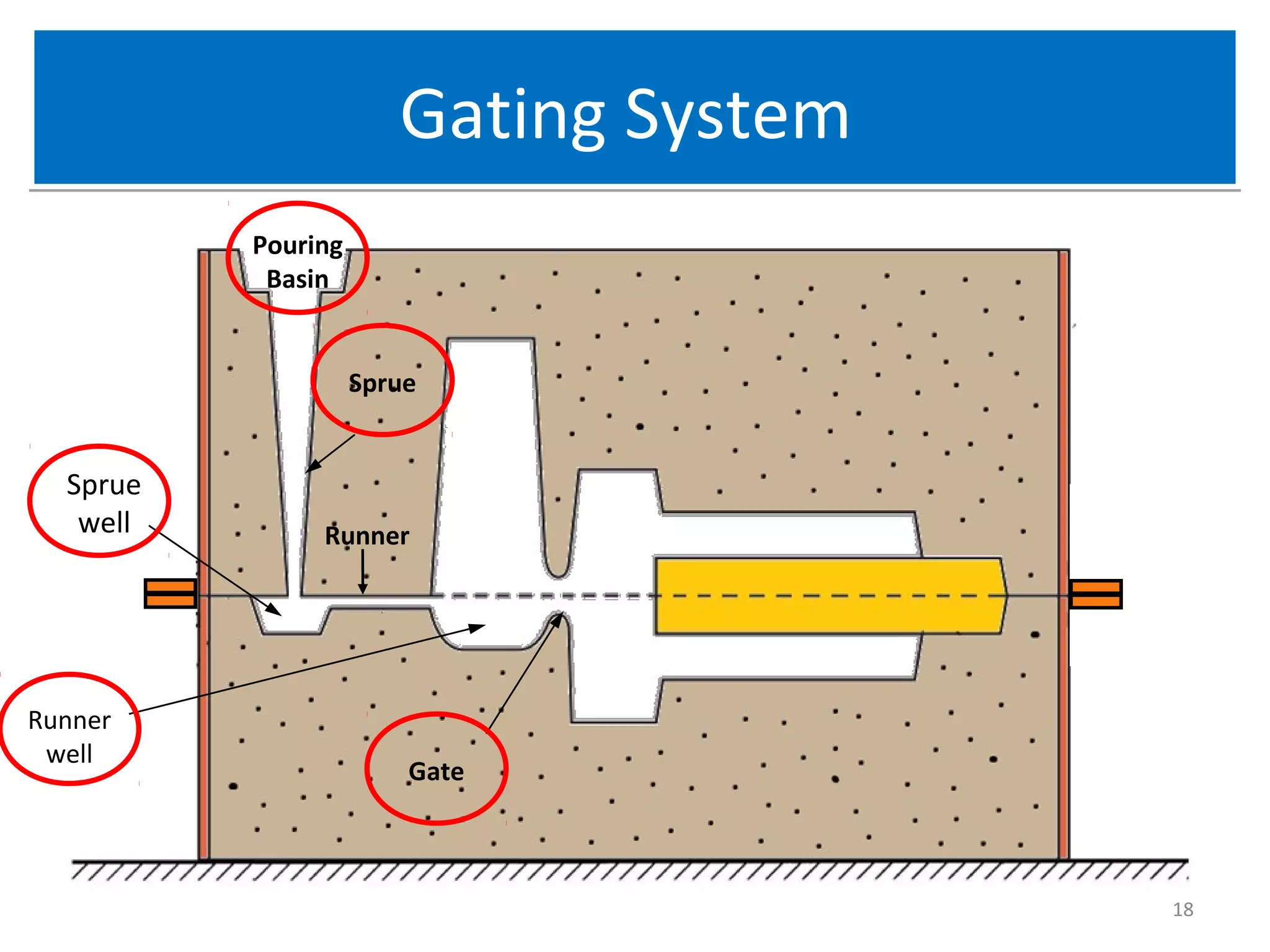
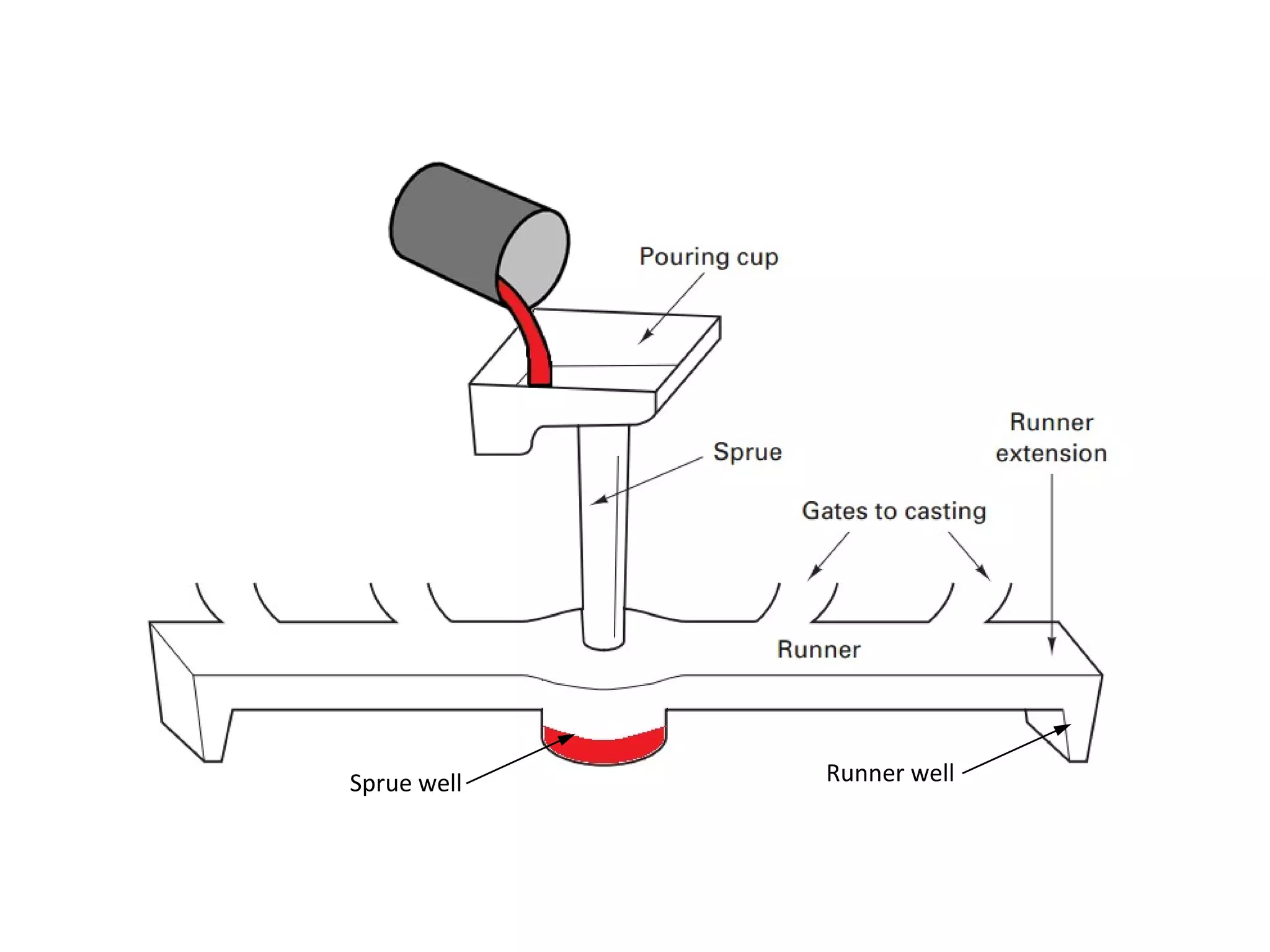
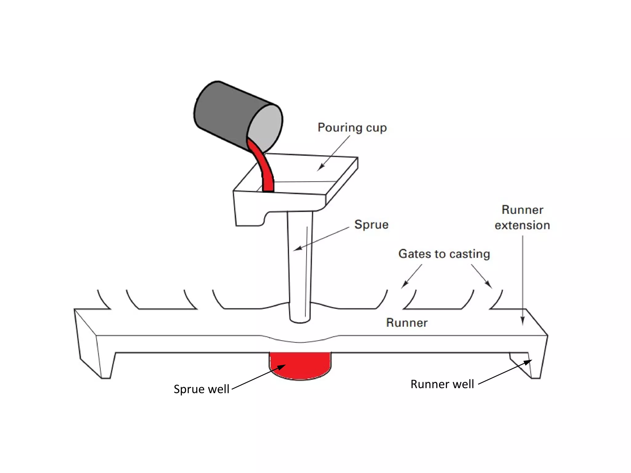
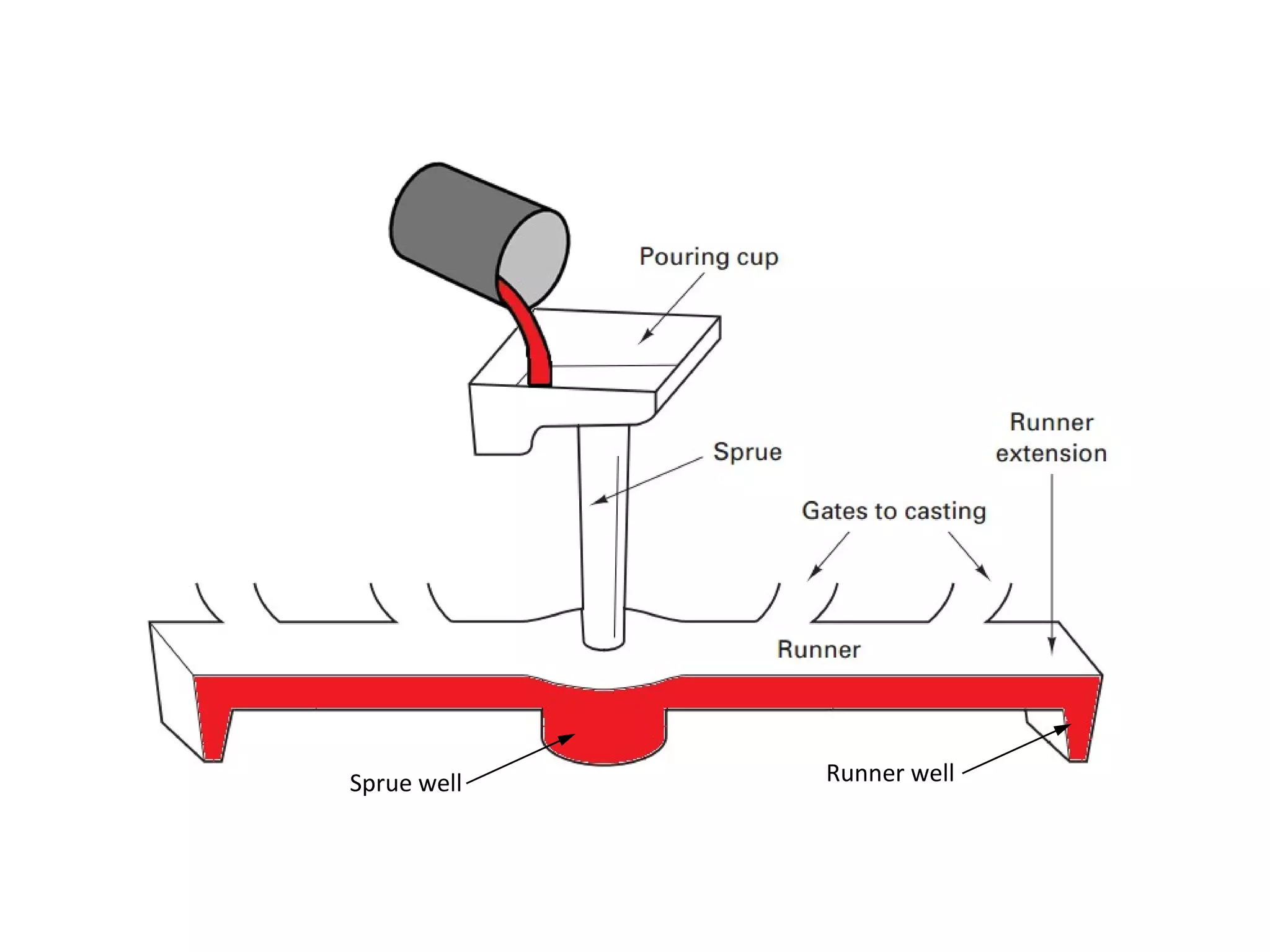
2. The Mold in CastingThe Mold in Casting
• The Mold contains a cavity whose geometry
determines the shape of the cast part.
• Mold is a hollow container(cavity) used to give
shape to molten or hot liquid material (such as
wax or metal) when it cools and hardens.
– Actual size and shape of cavity must be slightly
oversized to allow for shrinkage of metal during
solidification and cooling
– Molds are made of a variety of materials, including
sand, plaster, ceramic, and metal
2
3. Open Molds and Closed MoldsOpen Molds and Closed Molds
Two forms of mold: (a) open mold, simply a container in the shape
of the desired part; and (b) closed mold, in which the mold
geometry is more complex and requires a gating system
(passageway) leading into the cavity. 3
6. Forming the Mold CavityForming the Mold Cavity
• Mold cavity is formed by packing sand around a
pattern, which has the shape of the part
• When the pattern is removed, the remaining
cavity of the packed sand has desired shape of
cast part
• The pattern is usually oversized to allow for
shrinkage of metal during solidification and
cooling
• Sand for the mold is moist and contains a binder
to maintain its shape 6
7. Desirable Mold PropertiesDesirable Mold Properties
• The sand used to generally make molds is required
to meet four primary requirements –
• Refractoriness – ability to withstand high
temperature,
• Cohesiveness – ability to retain a given shape when
packed into the mold,
• Permeability – allow hot air and gases to pass
through voids in sand,
• Collapsibility – ability to accommodate metal
shrinkage after solidification and free the casting by
disintegration.
7
8. Use of a Core in the Mold CavityUse of a Core in the Mold Cavity
• The mold cavity provides the external surfaces
of the cast part
• In addition, a casting may have internal surfaces,
determined by a core, placed inside the mold
cavity to define the interior geometry of part
• In sand casting, cores are generally made of sand
8
9. CoreCore
• Core is a Full scale model of interior surfaces of‑
the part .
• It is inserted into the mold cavity prior to pouring
• The molten metal flows and solidifies between
the mold cavity and the core to form the
casting's internal surfaces
• May require supports to hold it in position in the
mold cavity during pouring, called chaplets .
9
10. CoreCore
10
(a) Core held in place in the mold cavity by chaplets, (b) possible
chaplet design, (c) casting with internal cavity.
11. ChapletsChaplets
• Chaplets are the supports provided to hold the
core in its position in the mold cavity during
pouring.
• Because the chaplets are positioned within the
mold cavity, they become an integral part of the
finished casting.
• Chaplets should therefore be of the same, or at
least comparable, composition as the material
being poured.
11
12. ChapletsChaplets
• They should be large enough that they do not
completely melt and permit the core to move,
• Since chaplets are one more source of possible
defects and may become a location of weakness
in the finished casting, efforts are generally
made to minimize their use.
12
13. Core PrintCore Print
• Where coring is required, provision should be
made to support the core inside the mold cavity.
• Core prints are used to serve this purpose.
• The core print is an added projection on the
pattern and it forms a seat in the mold on which
the sand core rests during pouring of the mold.
• The core print must be of adequate size and
shape so that it can support the weight of the
core during the casting operation.
13
14. Core PrintCore Print
• Depending upon the requirement a core can be placed
horizontal, vertical and can be hanged inside the mold cavity.
14
Core PrintCoreCore Print
15. Gating SystemGating System
• The gating system in a casting mold is the
channel, or network of channels, through which
molten metal flows into cavity from outside of
mold.
• The pouring cup(or pouring basin) is the portion
of the gating system that receives the molten
metal from the pouring vessel and delivers it to
the rest of the mold.
• Pouring cup is often used to minimize splash and
turbulence as the metal flows into downsprue.
15
16. Gating SystemGating System
• From the pouring cup, the metal travels down a
downsprue also called simply the sprue (the
vertical portion of the gating system),
• Then along horizontal channels, called runners ,
and finally through controlled entrances, or
gates, into the mold cavity.
16
19. Gating SystemGating System
• The gates are usually attached to the
1. thickest or heaviest sections of a casting to control
SHRINKAGE
2. to the bottom of the casting to minimize
TURBULENCE AND SPLASHING.
• For large castings, multiple gates and runners
may be used to introduce metal to more than
one point of the mold cavity.
19
20. Gating SystemGating System
• Turbulent flow is generated while pouring the
molten metal into the mold which causes the
following problems:
– absorption of gases,
– oxidation of the metal, and
– erosion of the mold.
• Therefore gating systems should be designed to
minimize turbulent flow.
20
21. Gating SystemGating System
• Short sprues are desirable, since they minimize
the distance that the metal must fall when
entering the mold.
• Rectangular pouring cups prevent the formation
of a vortex or spiraling funnel, which tends to
suck gas and oxides into the sprue.
• Tapered sprues also pre-vent vortex formation.
21
22. Gating SystemGating System
• A large sprue well can be used to dissipate the
kinetic energy of the falling stream and prevent
splashing and turbulence as the metal makes the
turn into the runner.
22
23. Gating SystemGating System
• The choke , or smallest cross-sectional area in
the gating system, serves to control the rate of
metal flow. If the choke is located:
– near the base of the sprue, flow through the runners
and gates is slowed and flow is rather smooth.
– at the gates, the metal might enter the mold cavity
with a fountain effect, an extremely turbulent mode
of flow, but the small connecting area would enable
easier separation of the casting and gating system.
23
24. Gating SystemGating System
• Gating systems can also be designed to trap
dross (slag) and sand particles and keep them
from entering the mold cavity.
• Screens or ceramic filters of various shapes,
sizes, and materials can also be inserted into the
gating system to trap foreign material.
• Wire mesh can often be used with the
nonferrous metals, but ceramic materials are
generally required for irons and steel.
24
32. RiserRiser
• A riser is an additional void in the mold that also
fills with molten metal.
• Riser is a reservoir of additional molten metal
that can flow into the mold to compensate for
shrinkage of the part during solidification .
• The riser must be designed to freeze after the
main casting in order to satisfy its function.
32
34. RiserRiser
• Live risers (also known as hot risers) receive the last
hot metal that enters the mold and generally do so
at a time when the metal in the mold cavity has
already begun to cool and solidify.
• Thus, they can be smaller than dead (or cold) risers,
which fill with metal that has already flowed
through the mold cavity.
• As shown in Figure, top risers are almost always
dead risers.
• Risers that are part of the gating system generally
live risers.
34
36. RiserRiser
• Open risers have the danger of solidifying first,
therefore they must be sized properly (larger) for
proper function.
• An open riser helps exhaust gases from the mold
during pouring, and can thereby eliminate some
associated defects.
• A blind riser that is not open to the atmosphere
may cause pockets of air to be trapped, or
increased dissolution of air into the metal,
leading to defects in the cast part.
36
37. Problems with Too Large RiserProblems with Too Large Riser
• The material in the riser is eventually scrapped
and has to be recycled; the riser has to be cut off,
and a larger riser will cost more to machine.
• An excessively large riser slows solidification.
• The riser may interfere with solidification
elsewhere in the casting.
• The extra metal may cause buoyancy forces
sufficient to separate the mold halves, unless
they are properly weighted or clamped
37
38. Problems with Too Small RiserProblems with Too Small Riser
• The drawbacks to having too small riser are
mainly associated with defects in the casting,
either due to insufficient feeding of liquid to
compensate for solidification shrinkage.
38
39. Riser LocationRiser Location
• A riser should be located in such a way that
directional solidification is obtained.
• Since the heaviest section of the casting solidifies
last, the riser should be located to feed this
section.
• The heaviest section will now act as a riser for
other sections which are not so heavy or thick.
• For small castings, a single riser can feed the
entire casting, but more than one riser is
required for large castings.
39
40. Vent holesVent holes
• As the metal flows into the mould, the air that
previously occupied the cavity, as well as hot gases
formed by reactions of the molten metal, must be
evacuated so that the metal will completely fill the
empty space.
• In sand casting, for example, the natural porosity of
the sand mould permits the air and gases to escape
through the walls of the cavity.
• In permanent-metal mould, small vent holes are
drilled into the mould or machined into the parting
line to permit removal of air and gases.
40