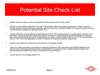
Site Verification


                 Site Verification in a Pre and Post AMI
                 World
                 Prepared by Tom Lawton,TESCO

                 for the Fall Southeastern Electricity Metering Association
                 Advanced Metering Track
10/02/2012       November 7, 2012
                       Slide 1
Premise
           Over much of the 20th century, utilities, regulators and
           customers each relied upon lab and field meter testing
           efforts which were primarily focused upon the accuracy of
           the watt-hour meter and demand register.

           This focus is now changing with overwhelming deployment
           of electronic meters and significant deployment of AMR and
           AMI meters throughout the installed base in North America.

           The focus has now shifted to the metering installation as a
           whole and not the accuracy of the meter.


11/07/12                             Slide 2
Field Testing
        Common Features and Common Sources of Concern


                    Electro Mechanical meters were subject to registration
                       errors caused by mechanical issues with moving parts
                       resulting in either the loss of revenue to the utility or
                       over billing for the customer. Some of the more
                       common problems were:

                    •   Friction wear
                    •   Gear mesh misalignment
                    •   Retarding magnet failure
                    •   Timing motors


10/02/2012                     Slide 3
Electronic Meters – new failure modes require new testing
                     and inspection methods

Electronic meters fail as do electro mechanical meters but differently

•      Their overall life expectancy is not nearly the same

•      Failure modes include drift (unexpected)

•      Failure modes include catastrophic (expected)

•      Failure modes include non-catastrophic but significant
       measurement error modes

•      Failure modes can include non-measurement issues which render
       the meter ineffective or inaccurate for billing purposes.


10/02/2012                         Slide 4
Best Practices
• Residential vs Commercial
• Self-contained vs Transformer Rated
• Follow the money and be as proactive as
  posible

                Plan                Execute


                       Analyze data


10/02/2012                Slide 5
Potential Site Check List
•   Double check the meter number, the location the test result and the meter record

•   Perform a visual safety inspection of the site. This includes utility and customer equipment. Things to look for
    include intact down ground on pole, properly attached enclosure, unwanted voltage on enclosure, proper trimming
    and site tidiness (absence of discarded seals, etc.)

•   Visually inspect for energy diversions (intentional and not). This includes broken or missing wires, jumpers, open
    test switch, unconnected wires and foreign objects on meters or other metering equipment. Broken or missing
    wires can seriously cause the under measurement of energy. A simple broken wire on a CT or VT can cause the
    loss of 1/3 to 1/2 of the registration on either 3 element or 2 element metering, respectively.

•   Visually check lightning arrestors and transformers for damage or leaks.

•   Check for proper grounding and bonding of metering equipment. Poor grounding and bonding practices may
    result in inaccurate measurements that go undetected for long periods of time. Implementing a single point
    ground policy and practice can reduce or eliminate this type of issue.

•   Burden test CTs and voltage check PTs.


10/02/2012                                            Slide 6
Potential Site Check List (cont)
•   Verify service voltage. Stuck regulator or seasonal capacitor can impact service voltage.

•   Verify condition of metering control wire. This includes looking for cracks in insulation, broken wires, loose
    connections, etc.

•   Compare the test switch wiring with the wiring at the CTs and VTs. Verify CTs and VTs not cross wired. Be sure
    CTs are grounded in one location (test switch) only.

•   Check for bad test switch by examining voltage at the top and bottom of the switch. Also verify amps using amp
    probe on both sides of the test switch. Verify neutral connection to cabinet (voltage).

•   Check rotation by closing in one phase at a time at the test switch and observing the phase meter for forward
    rotation. If forward rotation is not observed measurements may be significantly impacted as the phases are most
    likely cancelling each other out.

•   Test meter for accuracy. Verify demand if applicable with observed load. If meter is performing compensation
    (line and/or transformer losses) the compensation should be verified either through direct testing at the site or by
    examining recorded pulse data. Loss compensation is generally a very small percentage of the overall
    measurement and would not be caught under utilities normal high/low checks. However, the small percentages
    when applied to large loads or generation can really add up overtime. Billing adjustments can easily be in the
    $million range if not caught early.


10/02/2012                                             Slide 7
Potential Site Check List (cont)
•   Verify metering vectors. Traditionally this has been done using instruments such as a circuit analyzer. Many solid
    state meters today can provide vector diagrams along with volt/amp/pf and values using meter manufacturer
    software or meter displays. Many of these desired values are programmed into the meters Alternate/Utility
    display. Examining these values can provide much information about the metering integrity. It may also assist in
    determining if unbalanced loads are present and if CTs are sized properly. The vendor software generally has the
    ability to capture both diagnostic and vector information electronically. These electronic records should be kept in
    the meter shop for future comaparisons.

•   If metering is providing pulses/EOI pulse to customers, SCADA systems or other meters for totalization they also
    should be verified vs. the known load on the meter.

•   Verify meter information including meter multiplier (rework it), serial number, dials/decimals, Mp, Ke, Primary Kh,
    Kr and Rate. Errors in this type of information can also cause a adverse impact on measured/reported values.

•   Verify CT shunts are all opened.


10/02/2012                                            Slide 8
Shop Testing

•    Accuracy testing
•    Meter Communications
     Performance
•    Software and firmware
     verification
•    Setting verification
•    Functional testing
•    Disconnect/reconnect
     Functionality
     and as left setting


10/02/2012                   Slide 9
Testing Frequency and Cost
• Tools (hardware and
  software)
• Personnel
• Frequency
• Test
• Report
• Analyze
• Learn, Share, Adapt

10/02/2012              Slide 10
Questions and Discussion
             Tom Lawton
 TESCO – The Eastern Specialty Company
                         Bristol, PA
                     215-688-0298 (cell)
                      1-800-762-8211

         This presentation can also be found under Meter
        Conferences and Schools on the TESCO web site:
                     www.tesco-advent.com


10/02/2012                 Slide 11

TESCO Site Verification in a Pre and Post AMI World

  • 1.
    Site Verification Site Verification in a Pre and Post AMI World Prepared by Tom Lawton,TESCO for the Fall Southeastern Electricity Metering Association Advanced Metering Track 10/02/2012 November 7, 2012 Slide 1
  • 2.
    Premise Over much of the 20th century, utilities, regulators and customers each relied upon lab and field meter testing efforts which were primarily focused upon the accuracy of the watt-hour meter and demand register. This focus is now changing with overwhelming deployment of electronic meters and significant deployment of AMR and AMI meters throughout the installed base in North America. The focus has now shifted to the metering installation as a whole and not the accuracy of the meter. 11/07/12 Slide 2
  • 3.
    Field Testing Common Features and Common Sources of Concern Electro Mechanical meters were subject to registration errors caused by mechanical issues with moving parts resulting in either the loss of revenue to the utility or over billing for the customer. Some of the more common problems were: • Friction wear • Gear mesh misalignment • Retarding magnet failure • Timing motors 10/02/2012 Slide 3
  • 4.
    Electronic Meters –new failure modes require new testing and inspection methods Electronic meters fail as do electro mechanical meters but differently • Their overall life expectancy is not nearly the same • Failure modes include drift (unexpected) • Failure modes include catastrophic (expected) • Failure modes include non-catastrophic but significant measurement error modes • Failure modes can include non-measurement issues which render the meter ineffective or inaccurate for billing purposes. 10/02/2012 Slide 4
  • 5.
    Best Practices • Residentialvs Commercial • Self-contained vs Transformer Rated • Follow the money and be as proactive as posible Plan Execute Analyze data 10/02/2012 Slide 5
  • 6.
    Potential Site CheckList • Double check the meter number, the location the test result and the meter record • Perform a visual safety inspection of the site. This includes utility and customer equipment. Things to look for include intact down ground on pole, properly attached enclosure, unwanted voltage on enclosure, proper trimming and site tidiness (absence of discarded seals, etc.) • Visually inspect for energy diversions (intentional and not). This includes broken or missing wires, jumpers, open test switch, unconnected wires and foreign objects on meters or other metering equipment. Broken or missing wires can seriously cause the under measurement of energy. A simple broken wire on a CT or VT can cause the loss of 1/3 to 1/2 of the registration on either 3 element or 2 element metering, respectively. • Visually check lightning arrestors and transformers for damage or leaks. • Check for proper grounding and bonding of metering equipment. Poor grounding and bonding practices may result in inaccurate measurements that go undetected for long periods of time. Implementing a single point ground policy and practice can reduce or eliminate this type of issue. • Burden test CTs and voltage check PTs. 10/02/2012 Slide 6
  • 7.
    Potential Site CheckList (cont) • Verify service voltage. Stuck regulator or seasonal capacitor can impact service voltage. • Verify condition of metering control wire. This includes looking for cracks in insulation, broken wires, loose connections, etc. • Compare the test switch wiring with the wiring at the CTs and VTs. Verify CTs and VTs not cross wired. Be sure CTs are grounded in one location (test switch) only. • Check for bad test switch by examining voltage at the top and bottom of the switch. Also verify amps using amp probe on both sides of the test switch. Verify neutral connection to cabinet (voltage). • Check rotation by closing in one phase at a time at the test switch and observing the phase meter for forward rotation. If forward rotation is not observed measurements may be significantly impacted as the phases are most likely cancelling each other out. • Test meter for accuracy. Verify demand if applicable with observed load. If meter is performing compensation (line and/or transformer losses) the compensation should be verified either through direct testing at the site or by examining recorded pulse data. Loss compensation is generally a very small percentage of the overall measurement and would not be caught under utilities normal high/low checks. However, the small percentages when applied to large loads or generation can really add up overtime. Billing adjustments can easily be in the $million range if not caught early. 10/02/2012 Slide 7
  • 8.
    Potential Site CheckList (cont) • Verify metering vectors. Traditionally this has been done using instruments such as a circuit analyzer. Many solid state meters today can provide vector diagrams along with volt/amp/pf and values using meter manufacturer software or meter displays. Many of these desired values are programmed into the meters Alternate/Utility display. Examining these values can provide much information about the metering integrity. It may also assist in determining if unbalanced loads are present and if CTs are sized properly. The vendor software generally has the ability to capture both diagnostic and vector information electronically. These electronic records should be kept in the meter shop for future comaparisons. • If metering is providing pulses/EOI pulse to customers, SCADA systems or other meters for totalization they also should be verified vs. the known load on the meter. • Verify meter information including meter multiplier (rework it), serial number, dials/decimals, Mp, Ke, Primary Kh, Kr and Rate. Errors in this type of information can also cause a adverse impact on measured/reported values. • Verify CT shunts are all opened. 10/02/2012 Slide 8
  • 9.
    Shop Testing • Accuracy testing • Meter Communications Performance • Software and firmware verification • Setting verification • Functional testing • Disconnect/reconnect Functionality and as left setting 10/02/2012 Slide 9
  • 10.
    Testing Frequency andCost • Tools (hardware and software) • Personnel • Frequency • Test • Report • Analyze • Learn, Share, Adapt 10/02/2012 Slide 10
  • 11.
    Questions and Discussion Tom Lawton TESCO – The Eastern Specialty Company Bristol, PA 215-688-0298 (cell) 1-800-762-8211 This presentation can also be found under Meter Conferences and Schools on the TESCO web site: www.tesco-advent.com 10/02/2012 Slide 11