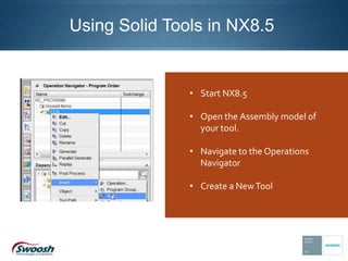
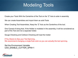
Using Solid Tools in NX8.5
By Brian Brown, Application Engineer, Swoosh Technologies
Using Solid Tools in NX8.5
• Start NX8.5
• Open the Assembly model of
your tool.
• Navigate to the Operations
Navigator
• Create a NewTool
• Enter your Tool’s Type
• Enter your Tool’s Name
• Select OK
• Enter the data on your
Tool Definition dialog box
as required for defining
any other new tool to
create a solid tool.
• Check the Export Tool
Part File
Note: When Specify the Mounting Junction the Centerline of the Tool MUST be on the X-axis of
the coordinate system.
When Specify the Tool Tip the Centerline of the Tool MUST be on the X-axis of the coordinate
system.
• When selecting the Export Tool Part
File the Junctions area becomes
active. You must specify both the
Mounting Junction and the Tool Tip
Junction.
• Specify the Mounting Junctions when
the Gage Line of the tool is taken from
on the holder.
• Specify the Tip of the tool on the tip.
When specifying the cutting area of the
tool, it will be dependent on how the
part is Modeling/Assembled.
• If the cutting tool is modeled as a
single body, select the single body.
• If the cutting tool is created in an
assembly as a series of bodies, only
select the actual cutting area.
• Export the body to the library.
• Select OK. Your tool should now be
entered into the library.
This Image is defining
the mounting junction
on the solid tool.
Notice the “Xaxis on
the Dynamic CSYS”
This image displays
the tool tip junction.
Notice the “Xaxis on
the Dynamic CSYS”
9
Modeling Tools
Create your Tools With the Centerline of the Tool on the “Z” Axis to aide in assembly
We can create Assemblies and import them as solid Tools
When Creating Tool Assemblies, Keep the “Z” Axis as the Centerline of the tool.
One Caveat of doing that, If the Holder is modeled in the assembly, It will be considered as
part of the Tool and not a separate holder.
Gouge Checking and Collision Checking will read the holder
If You Desire to See your Tool Spinning…
We recommend changing a single flute color so you can actually the tool spinning.
Set the Environment Variable
UGII_ENABLE_CUTTER_SPIN=1
Have Questions?
Contact Swoosh Technologies today!
www.SwooshTech.com
P: (314) 549-8110
F: (636) 778-9188
Check out the current NX training schedule here!
Thanks!

Using Solid Tools in NX 8.5

  • 1.
    Using Solid Toolsin NX8.5 By Brian Brown, Application Engineer, Swoosh Technologies
  • 2.
    Using Solid Toolsin NX8.5 • Start NX8.5 • Open the Assembly model of your tool. • Navigate to the Operations Navigator • Create a NewTool
  • 3.
    • Enter yourTool’s Type • Enter your Tool’s Name • Select OK
  • 4.
    • Enter thedata on your Tool Definition dialog box as required for defining any other new tool to create a solid tool. • Check the Export Tool Part File
  • 5.
    Note: When Specifythe Mounting Junction the Centerline of the Tool MUST be on the X-axis of the coordinate system. When Specify the Tool Tip the Centerline of the Tool MUST be on the X-axis of the coordinate system. • When selecting the Export Tool Part File the Junctions area becomes active. You must specify both the Mounting Junction and the Tool Tip Junction. • Specify the Mounting Junctions when the Gage Line of the tool is taken from on the holder. • Specify the Tip of the tool on the tip.
  • 6.
    When specifying thecutting area of the tool, it will be dependent on how the part is Modeling/Assembled. • If the cutting tool is modeled as a single body, select the single body. • If the cutting tool is created in an assembly as a series of bodies, only select the actual cutting area. • Export the body to the library. • Select OK. Your tool should now be entered into the library.
  • 7.
    This Image isdefining the mounting junction on the solid tool. Notice the “Xaxis on the Dynamic CSYS”
  • 8.
    This image displays thetool tip junction. Notice the “Xaxis on the Dynamic CSYS”
  • 9.
    9 Modeling Tools Create yourTools With the Centerline of the Tool on the “Z” Axis to aide in assembly We can create Assemblies and import them as solid Tools When Creating Tool Assemblies, Keep the “Z” Axis as the Centerline of the tool. One Caveat of doing that, If the Holder is modeled in the assembly, It will be considered as part of the Tool and not a separate holder. Gouge Checking and Collision Checking will read the holder If You Desire to See your Tool Spinning… We recommend changing a single flute color so you can actually the tool spinning. Set the Environment Variable UGII_ENABLE_CUTTER_SPIN=1
  • 10.
    Have Questions? Contact SwooshTechnologies today! www.SwooshTech.com P: (314) 549-8110 F: (636) 778-9188 Check out the current NX training schedule here! Thanks!