SlideShare a Scribd company logo
1 of 42
DIRECTIONAL CONTROL VALVE
• The primary function of a DC valve is to direct
or prevent fluid flow to specific piping or system
actuator.
• These valves usually consists of spool inside it
which is electrically/hydraulically controlled.
• There are two fundamental positions of these
valves :
1. Working Position
2. Normal Position
According to no. of valve ports and spool position
DC valve can be categorized into following :
1. 2-way, 2-position
2. 3-way, 2-position
3. 4-way, 2-position
4. 4-way, 3-position and many more…
Common Abbreviation used in Hydraulics
P =Pressure line
T =Tank Line
A,B =System Actuator line
X =Pilot Line
Y =Drain Line
Spool Position
2 - Way, 2 – Position DC Valve
3 –Way, 2 - Position DC Valve
4 –Way, 2 –Position DC Valve
4 –Way, 3 –Position DC Valve
Electrically actuated DC Valves are actuated
by means of solenoid. They can be single/double
actuated. When these solenoids are
the DC valves are shifted to Working
solenoid
energized
position.
Along with solenoid, there are spring
actuators which are used to shift the spool of a DC
valve to normal position when the solenoid is de-
energized.
Single solenoid, 2 –
position, Spring Offset
Double Solenoid, 2 - Position
Double Solenoid, 3 –Position,
Spring Centre
1. Continuous line –Flow line
2. Dashed line –Pilot , drain
3. Spring
4. Flow Restriction
5. Single Acting Cylinder
6. Double Acting Cylinder
7. 2-way, 2-position DC valve (NC)
8. 2-way, 2-position DCvalve (NO)
9. 3-way, 2-Position DCvalve(NO)
10. 3-way, 2-Position DCvalve (NC)
CommonHydraulic Symbols
11. 4-Way, 2-position DC valve
12. 4-way, 3-position DC valve
13. Solenoid actuated
14. Hydraulic Actuated
15. Check Valve
16. Pilot operated Check Valve
17. Pressure Relief valve
It is an electro-mechanical device that take
electrical energy and produces a linear force by the use
of magnetism. It is basically a winding of wire around a
metal core.
SOLENOID ACTUATED DC VALVES
When the solenoid is energized, the air gap is
closed quickly and a force is developed in the direction
of the valve spool.
SOLENOID CONTROLLED, PILOT-OPERATED
DCV
Although a valve could be shifted directly by the
force of a solenoid, large flow DCVs are most often
shifted using fluid at system pressure. Larger flow
valves demand larger shifting forces and it is no longer
practical to use a solenoid there.
CHECK VALVE
• A check valve, non-return valve or one-way
valve is a valve that normally allows fluid to flow
through it in only one direction.
• Check valves are two-port valves, meaning they
have two openings in the body, one for fluid to enter
and the other for fluid to leave.
• An important concept in check valves is the
cracking pressure which is the minimum upstream
pressure at which the valve will operate.
PILOT OPERATED CHECK VALVE
• This type of check valves are remotely operated
through any one of the directional valves.
• This is controlled by a pilot pressure line
which is indeed controlled by a directional control
valve.
Use of Circuit Symbols
Circuit symbols are used for components to enable clear representation of
hydraulic systems in diagrams
A symbol identifies a component and its function
The symbols in this course are based on DIN ISO 1219
The most important symbols are dealt with in this basic hydraulics course.
3. Hydraulic Components Symbols
3.1 Transfer of energy and condition of the pressure medium
Introduction
These symbols are
used in circuit
diagrams for energy
transfer components
and condition of
pressure medium
3. Hydraulic Components Symbols
Transfer of energy and condition of the pressure medium
Hydraulic Components Symbols
Hydraulic pump Hydraulic motor Type of Fluid
Pumps and Motors
Measuring Devices
Squares with arrows inside are used
for DCV symbol
Number of squares indicate number
of switching positions
Arrows within squares indicate flow
direction and how the ports are
interconnected in various switching
positions
P, T, R, A, B, L designations or labels
denote ports (A, B, C, D, E, …. Is
sometimes used)
The rest position is defined as the
position automatically assumed by
the valve in the absence of an
actuating force.
Hydraulic Components Symbols
Direction Control Valves (DCV)
Direction Control Valves (DCV) – Normally closed/Normally open - 2/2way and 3/2way
Direction Control Valves (DCV) – 4/3 way mid position closed or pump recirculation
3. Hydraulic Components Symbols
• Direction Control Valves (DCV) – Method of Actuation
3. Hydraulic Components Symbols
Square used for symbol
Ports labels used: P, T or A,B
Position of valve inside
square indicates whether
valve is normally open or
normally closed
Are either fixed or adjustable
pressure setting
Divided into Pressure relief
valve and pressure regulator
Pressure Valves
Fixed or Adjustable ,Example: Pressure Relief
valve
Hydraulic Components Symbols
3.6 Flow Control Valves
• Provide means to adjust
speed of the drive
component
3.7 Non-return valves and shut-off valves
Hydraulic Components Symbols
3.8 Hydraulic actuators 3.9 Non-return valves and shut-off valves
Single acting cylinders
Cylinder
Cushioning
3. Hydraulic Components Symbols
3.10 Combination of Devices
If several devices are brought together in a single housing, the symbols for the individual
devices are placed into a box made up of broken lines from which the connections are ready
for plugging
Example:
3. Hydraulic Components Symbols
4. Hydraulic Circuit Illustration
Circuit with 4/3-way valve -
pump by-pass (re-
circulating)
31
• Circuit with 3/2-way
valve
31
• Circuit with 4/2 –way
valve
31
X: Pilot line
A: I/P line to the checkvalve
B : O/P line from the check valve
• The main application of check valves is to hold
the pressure of a load and for safety purposes.
PROPORTIONAL VALVE
• The proportional DCV is actuated by means of
an electrical control signal. The control signal
influences the flow rate and flow direction.
• It is exactly the same as the solenoid valve
except that solenoid valve acts as ON/OFF switch
whereas this proportional solenoid valve can achieve
each and every point in between thus varying the flow
rate.
• Different flow rate is achieved by varying the i/p
current signal.
•The difference between a solenoid and a proportional
solenoid valve is in the construction of their spool.
• The Servo valve has a hydraulic pressure inlet and an
electrical input for the torque motor. The input current controls the
flapper position. The flapper position controls the pressure in rod
side or piston side of the cylinder. So, a current (+ or -) will position
the flapper, leading to a delta pressure on the servo, which cause
the servo to move in one direction or the other. Movement of the
servo ports hydraulic pressure to one side of the actuator or the
other, while porting the opposite side of the actuator to return.
• Flapper position is controlled by the electromagnetic torque
motor. A torque motor consists of two permanent magnets with a
coil winding attached to a magnetically permeable armature. The
armature is part of the flapper piece. When a current is applied to
the coils, magnetic flux acting on the ends of the armature is
developed. The direction of the magnetic flux (force) depends on the
sign (direction) of the current.
• The magnetic flux will cause the armature tips to be
attracted to the ends of the permanent magnets (current direction
determines which magnetic pole is attracting and which one is
repelling). This magnetic force creates an applied torque on the
flapper assembly, which is proportional to applied current.
• As the applied current is increased, the armature and
flapper will rotate. As the flapper moves closer to one nozzle, the flow
area through this nozzle is decreased while the flow area through
the other nozzle increases.
• In the above the figure the flapper nozzle consists of the
flapper, two inlet orifices (O1 and O2), two outlet nozzles (n1 and n2),
nozzle backpressure nozzle (n3) and usually a feedback spring. As
described above, the torque motor positions the flapper, which in
turns controls the flow through the nozzles. When the flapper is in
the neutral position, the nozzle flow areas are equal and the
pressures Pn1 and Pn2 are equal. When the flow areas and inlet
nozzle pressures are equal, the flow forces through each nozzle keep
the flapper centered in the neutral position.
• As the flapper moves towards one of the nozzles, the outlet
flow area is reduced for this nozzle. Outlet flow area increases for
the other nozzle. For example, looking at Figure let the flapper
move towards the n1 nozzle. This will reduce the outlet flow area
and the pressure Pn1 will increase. At the same time, the outlet
flow area at the n2 nozzle will increase and the pressure Pn2 will
decrease. A delta pressure ΔP = Pn1 – Pn2 will occur across the pilot
spool piston and the pilot spool will displace to the right. High
pressure fluid will then flow to the PA actuator chamber while the
PB actuator chamber is ported to return.
• Servo valves are normally used when accurate position
and force control is required.
• The main advantage of a servo valve is that a low power
electrical signal can be used to accurately position an actuator or
motor.
• The disadvantage is complexity and cost which results
from a component consisting of many detail parts manufactured
to very tight tolerances. Therefore, servo valves should only be
used when accurate position (or rate) control is required.
SERVO VALVE CONNECTOR
PIN FUNCTION VOLTAGE /
CURRENT RATING
A SUPPLY VOLTAGE 24 V DC
B GROUND
C ENABLE INPUT < 6. 5 VDCDISABLED
D COMMAND SIGNAL I/P -10 to +10 mA OR
E 4 – 20 mA
F COMMAND SIGNAL O/P 4 – 20 mA
G P.E.
SERVO CONNECTOR
24 v dc
A B C D E
G CONNECTOR
(4 – 20 mA)
X Y
POTENTIOMETER
In No Load Condition
When the wiper is at ‘X’ end :
Current across DE will be, 24/970 = 24 mA (Apprx. )
When the wiper is at ‘Y’ end :
Current across DE will be 0 mA.

More Related Content

What's hot

Introduction to hydraulics and pneumatic by Varun Pratap Singh
Introduction to hydraulics and pneumatic by Varun Pratap SinghIntroduction to hydraulics and pneumatic by Varun Pratap Singh
Introduction to hydraulics and pneumatic by Varun Pratap SinghVarun Pratap Singh
 
Fundamental of hydraulic components
Fundamental of hydraulic componentsFundamental of hydraulic components
Fundamental of hydraulic componentsPrasadroshan Mythin
 
Hyraulics and Pneumatics
Hyraulics and Pneumatics Hyraulics and Pneumatics
Hyraulics and Pneumatics ravikumarmrk
 
Mechanical drives & power transmission
Mechanical drives & power transmissionMechanical drives & power transmission
Mechanical drives & power transmissionJames Shearer
 
Design of hydraulic circuits
Design of hydraulic circuitsDesign of hydraulic circuits
Design of hydraulic circuitsHardik Siddhpura
 
Pneumatics & Hydraulics
Pneumatics & HydraulicsPneumatics & Hydraulics
Pneumatics & HydraulicsJHALAKNIHALANI
 
Fluid power introduction
Fluid power introductionFluid power introduction
Fluid power introductionsukusobhaa
 
Presentation on pneumatic actuator
Presentation on pneumatic actuatorPresentation on pneumatic actuator
Presentation on pneumatic actuatorManish Tiwari
 
Applications of Pneumatic System with Machines
Applications of  Pneumatic System with MachinesApplications of  Pneumatic System with Machines
Applications of Pneumatic System with MachinesMohammad Azam Khan
 
Hydraulic Valves and Hydraulic System Accessories
Hydraulic Valves and Hydraulic System AccessoriesHydraulic Valves and Hydraulic System Accessories
Hydraulic Valves and Hydraulic System AccessoriesRAHUL THAKER
 
Hydraulic & Peumatic Systems
Hydraulic & Peumatic SystemsHydraulic & Peumatic Systems
Hydraulic & Peumatic SystemsShubham Thakur
 
Electro hydraulic system Components and their operation
Electro hydraulic system Components and their operationElectro hydraulic system Components and their operation
Electro hydraulic system Components and their operationSrichandan Subudhi
 
Pneumatic valves
Pneumatic valvesPneumatic valves
Pneumatic valvesWaqar Aziz
 

What's hot (20)

Introduction to hydraulics and pneumatic by Varun Pratap Singh
Introduction to hydraulics and pneumatic by Varun Pratap SinghIntroduction to hydraulics and pneumatic by Varun Pratap Singh
Introduction to hydraulics and pneumatic by Varun Pratap Singh
 
Fundamental of hydraulic components
Fundamental of hydraulic componentsFundamental of hydraulic components
Fundamental of hydraulic components
 
Hyraulics and Pneumatics
Hyraulics and Pneumatics Hyraulics and Pneumatics
Hyraulics and Pneumatics
 
Mechanical drives & power transmission
Mechanical drives & power transmissionMechanical drives & power transmission
Mechanical drives & power transmission
 
Hydraulic motors
Hydraulic motorsHydraulic motors
Hydraulic motors
 
Design of hydraulic circuits
Design of hydraulic circuitsDesign of hydraulic circuits
Design of hydraulic circuits
 
Pneumatics & Hydraulics
Pneumatics & HydraulicsPneumatics & Hydraulics
Pneumatics & Hydraulics
 
DIRECTION CONTROL VALVE
DIRECTION CONTROL VALVEDIRECTION CONTROL VALVE
DIRECTION CONTROL VALVE
 
Hydraulic actuators
Hydraulic actuatorsHydraulic actuators
Hydraulic actuators
 
Hydraulic system
Hydraulic systemHydraulic system
Hydraulic system
 
Fluid power introduction
Fluid power introductionFluid power introduction
Fluid power introduction
 
Servo Valves
Servo Valves Servo Valves
Servo Valves
 
Hidraulic Symbols
Hidraulic Symbols Hidraulic Symbols
Hidraulic Symbols
 
Presentation on pneumatic actuator
Presentation on pneumatic actuatorPresentation on pneumatic actuator
Presentation on pneumatic actuator
 
Industrial hydraulics
Industrial hydraulicsIndustrial hydraulics
Industrial hydraulics
 
Applications of Pneumatic System with Machines
Applications of  Pneumatic System with MachinesApplications of  Pneumatic System with Machines
Applications of Pneumatic System with Machines
 
Hydraulic Valves and Hydraulic System Accessories
Hydraulic Valves and Hydraulic System AccessoriesHydraulic Valves and Hydraulic System Accessories
Hydraulic Valves and Hydraulic System Accessories
 
Hydraulic & Peumatic Systems
Hydraulic & Peumatic SystemsHydraulic & Peumatic Systems
Hydraulic & Peumatic Systems
 
Electro hydraulic system Components and their operation
Electro hydraulic system Components and their operationElectro hydraulic system Components and their operation
Electro hydraulic system Components and their operation
 
Pneumatic valves
Pneumatic valvesPneumatic valves
Pneumatic valves
 

Similar to 4 fluid power ansi symbols

3 valve shafts pneumatics and hydraulics
3 valve shafts pneumatics and hydraulics3 valve shafts pneumatics and hydraulics
3 valve shafts pneumatics and hydraulicsaman520305
 
Unit-3.pdf mechanical enginnering hydraulics
Unit-3.pdf mechanical enginnering hydraulicsUnit-3.pdf mechanical enginnering hydraulics
Unit-3.pdf mechanical enginnering hydraulicsMuditK4
 
spool actuation method
spool actuation methodspool actuation method
spool actuation methodShrenik Baid
 
Week 3 1_hydraulics_valve3
Week 3 1_hydraulics_valve3Week 3 1_hydraulics_valve3
Week 3 1_hydraulics_valve3akmal ariffin
 
Session 06 - Instruments - Part 2
Session 06 - Instruments - Part 2Session 06 - Instruments - Part 2
Session 06 - Instruments - Part 2VidyaIA
 
HYDRAULIC AND PNEUMATIC ACTUATOR
HYDRAULIC AND PNEUMATIC ACTUATORHYDRAULIC AND PNEUMATIC ACTUATOR
HYDRAULIC AND PNEUMATIC ACTUATORKANA RAM MEENA
 
application of Direction control valve in automatic transmission
application of Direction control valve in automatic transmissionapplication of Direction control valve in automatic transmission
application of Direction control valve in automatic transmissionZIYAD AMBALANGADAN
 
Hydraulic and pneumatic control elements
Hydraulic and pneumatic control elementsHydraulic and pneumatic control elements
Hydraulic and pneumatic control elementsumesh chikhale
 
Hydraulics & pneumatics (AU) Unit-II
Hydraulics & pneumatics (AU)   Unit-IIHydraulics & pneumatics (AU)   Unit-II
Hydraulics & pneumatics (AU) Unit-IIArul Prakasam G
 
chter 3 actuators.pdffejvrvfdvkceckevsvd
chter 3 actuators.pdffejvrvfdvkceckevsvdchter 3 actuators.pdffejvrvfdvkceckevsvd
chter 3 actuators.pdffejvrvfdvkceckevsvdAdugnaGosa1
 
Hydraulic Circuit Contents..pptx
Hydraulic Circuit Contents..pptxHydraulic Circuit Contents..pptx
Hydraulic Circuit Contents..pptxAhmdSbhy
 
Module 3 hydraulic control valves
Module 3 hydraulic control valvesModule 3 hydraulic control valves
Module 3 hydraulic control valvessrinivaspp
 
Actuators and optical speed sensor and application in automatic transmission
Actuators and optical speed sensor and application in automatic transmissionActuators and optical speed sensor and application in automatic transmission
Actuators and optical speed sensor and application in automatic transmissionZIYAD AMBALANGADAN
 
4 hydraulic servo system
4 hydraulic servo system4 hydraulic servo system
4 hydraulic servo systemDr.R. SELVAM
 
Instrumentation positioner presentation
Instrumentation positioner presentationInstrumentation positioner presentation
Instrumentation positioner presentationSANGRAM PATNAIK
 
an introduction to electro pneumatic and
an introduction to electro pneumatic andan introduction to electro pneumatic and
an introduction to electro pneumatic andsimachewyangson111
 

Similar to 4 fluid power ansi symbols (20)

3 valve shafts pneumatics and hydraulics
3 valve shafts pneumatics and hydraulics3 valve shafts pneumatics and hydraulics
3 valve shafts pneumatics and hydraulics
 
Unit-3.pdf mechanical enginnering hydraulics
Unit-3.pdf mechanical enginnering hydraulicsUnit-3.pdf mechanical enginnering hydraulics
Unit-3.pdf mechanical enginnering hydraulics
 
1_Control Valves.ppt
1_Control Valves.ppt1_Control Valves.ppt
1_Control Valves.ppt
 
Dc valve
Dc  valve Dc  valve
Dc valve
 
spool actuation method
spool actuation methodspool actuation method
spool actuation method
 
Week 3 1_hydraulics_valve3
Week 3 1_hydraulics_valve3Week 3 1_hydraulics_valve3
Week 3 1_hydraulics_valve3
 
Session 06 - Instruments - Part 2
Session 06 - Instruments - Part 2Session 06 - Instruments - Part 2
Session 06 - Instruments - Part 2
 
HYDRAULIC AND PNEUMATIC ACTUATOR
HYDRAULIC AND PNEUMATIC ACTUATORHYDRAULIC AND PNEUMATIC ACTUATOR
HYDRAULIC AND PNEUMATIC ACTUATOR
 
Instruments - Part 2
Instruments - Part 2Instruments - Part 2
Instruments - Part 2
 
application of Direction control valve in automatic transmission
application of Direction control valve in automatic transmissionapplication of Direction control valve in automatic transmission
application of Direction control valve in automatic transmission
 
Hydraulic and pneumatic control elements
Hydraulic and pneumatic control elementsHydraulic and pneumatic control elements
Hydraulic and pneumatic control elements
 
Hydraulics & pneumatics (AU) Unit-II
Hydraulics & pneumatics (AU)   Unit-IIHydraulics & pneumatics (AU)   Unit-II
Hydraulics & pneumatics (AU) Unit-II
 
chter 3 actuators.pdffejvrvfdvkceckevsvd
chter 3 actuators.pdffejvrvfdvkceckevsvdchter 3 actuators.pdffejvrvfdvkceckevsvd
chter 3 actuators.pdffejvrvfdvkceckevsvd
 
Hydraulic Circuit Contents..pptx
Hydraulic Circuit Contents..pptxHydraulic Circuit Contents..pptx
Hydraulic Circuit Contents..pptx
 
Actuators
ActuatorsActuators
Actuators
 
Module 3 hydraulic control valves
Module 3 hydraulic control valvesModule 3 hydraulic control valves
Module 3 hydraulic control valves
 
Actuators and optical speed sensor and application in automatic transmission
Actuators and optical speed sensor and application in automatic transmissionActuators and optical speed sensor and application in automatic transmission
Actuators and optical speed sensor and application in automatic transmission
 
4 hydraulic servo system
4 hydraulic servo system4 hydraulic servo system
4 hydraulic servo system
 
Instrumentation positioner presentation
Instrumentation positioner presentationInstrumentation positioner presentation
Instrumentation positioner presentation
 
an introduction to electro pneumatic and
an introduction to electro pneumatic andan introduction to electro pneumatic and
an introduction to electro pneumatic and
 

More from Dr.R. SELVAM

7 breakeven analysis
7 breakeven analysis7 breakeven analysis
7 breakeven analysisDr.R. SELVAM
 
6 fixed assets, current assets, depreciation methods
6 fixed assets, current assets, depreciation methods6 fixed assets, current assets, depreciation methods
6 fixed assets, current assets, depreciation methodsDr.R. SELVAM
 
5 preparation and interpretation of balance sheets
5 preparation and interpretation of balance sheets5 preparation and interpretation of balance sheets
5 preparation and interpretation of balance sheetsDr.R. SELVAM
 
4 acounting principle
4 acounting principle4 acounting principle
4 acounting principleDr.R. SELVAM
 
3 capital structure
3 capital structure3 capital structure
3 capital structureDr.R. SELVAM
 
1 sources of finance
1 sources of finance1 sources of finance
1 sources of financeDr.R. SELVAM
 
4 b. capital budgeting and cost analysis performance evaluation
4 b. capital budgeting and cost analysis   performance evaluation4 b. capital budgeting and cost analysis   performance evaluation
4 b. capital budgeting and cost analysis performance evaluationDr.R. SELVAM
 
4 a. capital budgeting and cost analysis
4 a. capital budgeting and cost analysis4 a. capital budgeting and cost analysis
4 a. capital budgeting and cost analysisDr.R. SELVAM
 
3 capital budgeting
3 capital budgeting3 capital budgeting
3 capital budgetingDr.R. SELVAM
 
1 current assement management
1 current assement management1 current assement management
1 current assement managementDr.R. SELVAM
 
2 b. project termination
2 b. project termination2 b. project termination
2 b. project terminationDr.R. SELVAM
 
2 a. project auditing
2 a. project auditing2 a. project auditing
2 a. project auditingDr.R. SELVAM
 
1 b, evaluation of project
1 b, evaluation of project1 b, evaluation of project
1 b, evaluation of projectDr.R. SELVAM
 
1 a, monitoring and evaluation of PM
1 a, monitoring and evaluation of PM1 a, monitoring and evaluation of PM
1 a, monitoring and evaluation of PMDr.R. SELVAM
 
3 industrial hydraulic circuits shapping, milling, drilling
3 industrial hydraulic circuits   shapping, milling, drilling3 industrial hydraulic circuits   shapping, milling, drilling
3 industrial hydraulic circuits shapping, milling, drillingDr.R. SELVAM
 
2 maintenance of hydraulic systems
2 maintenance of hydraulic systems2 maintenance of hydraulic systems
2 maintenance of hydraulic systemsDr.R. SELVAM
 
1 hydraulic troubleshooting
1 hydraulic troubleshooting1 hydraulic troubleshooting
1 hydraulic troubleshootingDr.R. SELVAM
 
3 c. industrial pneumatic circuit logic
3 c. industrial pneumatic circuit   logic3 c. industrial pneumatic circuit   logic
3 c. industrial pneumatic circuit logicDr.R. SELVAM
 

More from Dr.R. SELVAM (20)

7 breakeven analysis
7 breakeven analysis7 breakeven analysis
7 breakeven analysis
 
6 fixed assets, current assets, depreciation methods
6 fixed assets, current assets, depreciation methods6 fixed assets, current assets, depreciation methods
6 fixed assets, current assets, depreciation methods
 
5 preparation and interpretation of balance sheets
5 preparation and interpretation of balance sheets5 preparation and interpretation of balance sheets
5 preparation and interpretation of balance sheets
 
4 acounting principle
4 acounting principle4 acounting principle
4 acounting principle
 
3 capital structure
3 capital structure3 capital structure
3 capital structure
 
1 sources of finance
1 sources of finance1 sources of finance
1 sources of finance
 
2 term loan
2 term loan2 term loan
2 term loan
 
4 b. capital budgeting and cost analysis performance evaluation
4 b. capital budgeting and cost analysis   performance evaluation4 b. capital budgeting and cost analysis   performance evaluation
4 b. capital budgeting and cost analysis performance evaluation
 
4 a. capital budgeting and cost analysis
4 a. capital budgeting and cost analysis4 a. capital budgeting and cost analysis
4 a. capital budgeting and cost analysis
 
3 capital budgeting
3 capital budgeting3 capital budgeting
3 capital budgeting
 
2 working capital
2 working capital2 working capital
2 working capital
 
1 current assement management
1 current assement management1 current assement management
1 current assement management
 
2 b. project termination
2 b. project termination2 b. project termination
2 b. project termination
 
2 a. project auditing
2 a. project auditing2 a. project auditing
2 a. project auditing
 
1 b, evaluation of project
1 b, evaluation of project1 b, evaluation of project
1 b, evaluation of project
 
1 a, monitoring and evaluation of PM
1 a, monitoring and evaluation of PM1 a, monitoring and evaluation of PM
1 a, monitoring and evaluation of PM
 
3 industrial hydraulic circuits shapping, milling, drilling
3 industrial hydraulic circuits   shapping, milling, drilling3 industrial hydraulic circuits   shapping, milling, drilling
3 industrial hydraulic circuits shapping, milling, drilling
 
2 maintenance of hydraulic systems
2 maintenance of hydraulic systems2 maintenance of hydraulic systems
2 maintenance of hydraulic systems
 
1 hydraulic troubleshooting
1 hydraulic troubleshooting1 hydraulic troubleshooting
1 hydraulic troubleshooting
 
3 c. industrial pneumatic circuit logic
3 c. industrial pneumatic circuit   logic3 c. industrial pneumatic circuit   logic
3 c. industrial pneumatic circuit logic
 

Recently uploaded

Fostering Friendships - Enhancing Social Bonds in the Classroom
Fostering Friendships - Enhancing Social Bonds  in the ClassroomFostering Friendships - Enhancing Social Bonds  in the Classroom
Fostering Friendships - Enhancing Social Bonds in the ClassroomPooky Knightsmith
 
Plant propagation: Sexual and Asexual propapagation.pptx
Plant propagation: Sexual and Asexual propapagation.pptxPlant propagation: Sexual and Asexual propapagation.pptx
Plant propagation: Sexual and Asexual propapagation.pptxUmeshTimilsina1
 
Philosophy of china and it's charactistics
Philosophy of china and it's charactisticsPhilosophy of china and it's charactistics
Philosophy of china and it's charactisticshameyhk98
 
How to Add New Custom Addons Path in Odoo 17
How to Add New Custom Addons Path in Odoo 17How to Add New Custom Addons Path in Odoo 17
How to Add New Custom Addons Path in Odoo 17Celine George
 
How to setup Pycharm environment for Odoo 17.pptx
How to setup Pycharm environment for Odoo 17.pptxHow to setup Pycharm environment for Odoo 17.pptx
How to setup Pycharm environment for Odoo 17.pptxCeline George
 
Jamworks pilot and AI at Jisc (20/03/2024)
Jamworks pilot and AI at Jisc (20/03/2024)Jamworks pilot and AI at Jisc (20/03/2024)
Jamworks pilot and AI at Jisc (20/03/2024)Jisc
 
Beyond_Borders_Understanding_Anime_and_Manga_Fandom_A_Comprehensive_Audience_...
Beyond_Borders_Understanding_Anime_and_Manga_Fandom_A_Comprehensive_Audience_...Beyond_Borders_Understanding_Anime_and_Manga_Fandom_A_Comprehensive_Audience_...
Beyond_Borders_Understanding_Anime_and_Manga_Fandom_A_Comprehensive_Audience_...Pooja Bhuva
 
Sociology 101 Demonstration of Learning Exhibit
Sociology 101 Demonstration of Learning ExhibitSociology 101 Demonstration of Learning Exhibit
Sociology 101 Demonstration of Learning Exhibitjbellavia9
 
ICT role in 21st century education and it's challenges.
ICT role in 21st century education and it's challenges.ICT role in 21st century education and it's challenges.
ICT role in 21st century education and it's challenges.MaryamAhmad92
 
Google Gemini An AI Revolution in Education.pptx
Google Gemini An AI Revolution in Education.pptxGoogle Gemini An AI Revolution in Education.pptx
Google Gemini An AI Revolution in Education.pptxDr. Sarita Anand
 
Python Notes for mca i year students osmania university.docx
Python Notes for mca i year students osmania university.docxPython Notes for mca i year students osmania university.docx
Python Notes for mca i year students osmania university.docxRamakrishna Reddy Bijjam
 
On National Teacher Day, meet the 2024-25 Kenan Fellows
On National Teacher Day, meet the 2024-25 Kenan FellowsOn National Teacher Day, meet the 2024-25 Kenan Fellows
On National Teacher Day, meet the 2024-25 Kenan FellowsMebane Rash
 
How to Create and Manage Wizard in Odoo 17
How to Create and Manage Wizard in Odoo 17How to Create and Manage Wizard in Odoo 17
How to Create and Manage Wizard in Odoo 17Celine George
 
latest AZ-104 Exam Questions and Answers
latest AZ-104 Exam Questions and Answerslatest AZ-104 Exam Questions and Answers
latest AZ-104 Exam Questions and Answersdalebeck957
 
FSB Advising Checklist - Orientation 2024
FSB Advising Checklist - Orientation 2024FSB Advising Checklist - Orientation 2024
FSB Advising Checklist - Orientation 2024Elizabeth Walsh
 
HMCS Vancouver Pre-Deployment Brief - May 2024 (Web Version).pptx
HMCS Vancouver Pre-Deployment Brief - May 2024 (Web Version).pptxHMCS Vancouver Pre-Deployment Brief - May 2024 (Web Version).pptx
HMCS Vancouver Pre-Deployment Brief - May 2024 (Web Version).pptxmarlenawright1
 
Interdisciplinary_Insights_Data_Collection_Methods.pptx
Interdisciplinary_Insights_Data_Collection_Methods.pptxInterdisciplinary_Insights_Data_Collection_Methods.pptx
Interdisciplinary_Insights_Data_Collection_Methods.pptxPooja Bhuva
 
Salient Features of India constitution especially power and functions
Salient Features of India constitution especially power and functionsSalient Features of India constitution especially power and functions
Salient Features of India constitution especially power and functionsKarakKing
 
SOC 101 Demonstration of Learning Presentation
SOC 101 Demonstration of Learning PresentationSOC 101 Demonstration of Learning Presentation
SOC 101 Demonstration of Learning Presentationcamerronhm
 

Recently uploaded (20)

Fostering Friendships - Enhancing Social Bonds in the Classroom
Fostering Friendships - Enhancing Social Bonds  in the ClassroomFostering Friendships - Enhancing Social Bonds  in the Classroom
Fostering Friendships - Enhancing Social Bonds in the Classroom
 
Plant propagation: Sexual and Asexual propapagation.pptx
Plant propagation: Sexual and Asexual propapagation.pptxPlant propagation: Sexual and Asexual propapagation.pptx
Plant propagation: Sexual and Asexual propapagation.pptx
 
Philosophy of china and it's charactistics
Philosophy of china and it's charactisticsPhilosophy of china and it's charactistics
Philosophy of china and it's charactistics
 
How to Add New Custom Addons Path in Odoo 17
How to Add New Custom Addons Path in Odoo 17How to Add New Custom Addons Path in Odoo 17
How to Add New Custom Addons Path in Odoo 17
 
How to setup Pycharm environment for Odoo 17.pptx
How to setup Pycharm environment for Odoo 17.pptxHow to setup Pycharm environment for Odoo 17.pptx
How to setup Pycharm environment for Odoo 17.pptx
 
Jamworks pilot and AI at Jisc (20/03/2024)
Jamworks pilot and AI at Jisc (20/03/2024)Jamworks pilot and AI at Jisc (20/03/2024)
Jamworks pilot and AI at Jisc (20/03/2024)
 
Beyond_Borders_Understanding_Anime_and_Manga_Fandom_A_Comprehensive_Audience_...
Beyond_Borders_Understanding_Anime_and_Manga_Fandom_A_Comprehensive_Audience_...Beyond_Borders_Understanding_Anime_and_Manga_Fandom_A_Comprehensive_Audience_...
Beyond_Borders_Understanding_Anime_and_Manga_Fandom_A_Comprehensive_Audience_...
 
Sociology 101 Demonstration of Learning Exhibit
Sociology 101 Demonstration of Learning ExhibitSociology 101 Demonstration of Learning Exhibit
Sociology 101 Demonstration of Learning Exhibit
 
ICT role in 21st century education and it's challenges.
ICT role in 21st century education and it's challenges.ICT role in 21st century education and it's challenges.
ICT role in 21st century education and it's challenges.
 
Google Gemini An AI Revolution in Education.pptx
Google Gemini An AI Revolution in Education.pptxGoogle Gemini An AI Revolution in Education.pptx
Google Gemini An AI Revolution in Education.pptx
 
Python Notes for mca i year students osmania university.docx
Python Notes for mca i year students osmania university.docxPython Notes for mca i year students osmania university.docx
Python Notes for mca i year students osmania university.docx
 
On National Teacher Day, meet the 2024-25 Kenan Fellows
On National Teacher Day, meet the 2024-25 Kenan FellowsOn National Teacher Day, meet the 2024-25 Kenan Fellows
On National Teacher Day, meet the 2024-25 Kenan Fellows
 
How to Create and Manage Wizard in Odoo 17
How to Create and Manage Wizard in Odoo 17How to Create and Manage Wizard in Odoo 17
How to Create and Manage Wizard in Odoo 17
 
latest AZ-104 Exam Questions and Answers
latest AZ-104 Exam Questions and Answerslatest AZ-104 Exam Questions and Answers
latest AZ-104 Exam Questions and Answers
 
FSB Advising Checklist - Orientation 2024
FSB Advising Checklist - Orientation 2024FSB Advising Checklist - Orientation 2024
FSB Advising Checklist - Orientation 2024
 
HMCS Vancouver Pre-Deployment Brief - May 2024 (Web Version).pptx
HMCS Vancouver Pre-Deployment Brief - May 2024 (Web Version).pptxHMCS Vancouver Pre-Deployment Brief - May 2024 (Web Version).pptx
HMCS Vancouver Pre-Deployment Brief - May 2024 (Web Version).pptx
 
Mehran University Newsletter Vol-X, Issue-I, 2024
Mehran University Newsletter Vol-X, Issue-I, 2024Mehran University Newsletter Vol-X, Issue-I, 2024
Mehran University Newsletter Vol-X, Issue-I, 2024
 
Interdisciplinary_Insights_Data_Collection_Methods.pptx
Interdisciplinary_Insights_Data_Collection_Methods.pptxInterdisciplinary_Insights_Data_Collection_Methods.pptx
Interdisciplinary_Insights_Data_Collection_Methods.pptx
 
Salient Features of India constitution especially power and functions
Salient Features of India constitution especially power and functionsSalient Features of India constitution especially power and functions
Salient Features of India constitution especially power and functions
 
SOC 101 Demonstration of Learning Presentation
SOC 101 Demonstration of Learning PresentationSOC 101 Demonstration of Learning Presentation
SOC 101 Demonstration of Learning Presentation
 

4 fluid power ansi symbols

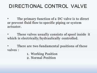
  • 1. DIRECTIONAL CONTROL VALVE • The primary function of a DC valve is to direct or prevent fluid flow to specific piping or system actuator. • These valves usually consists of spool inside it which is electrically/hydraulically controlled. • There are two fundamental positions of these valves : 1. Working Position 2. Normal Position
  • 2. According to no. of valve ports and spool position DC valve can be categorized into following : 1. 2-way, 2-position 2. 3-way, 2-position 3. 4-way, 2-position 4. 4-way, 3-position and many more…
  • 3. Common Abbreviation used in Hydraulics P =Pressure line T =Tank Line A,B =System Actuator line X =Pilot Line Y =Drain Line
  • 5. 2 - Way, 2 – Position DC Valve
  • 6. 3 –Way, 2 - Position DC Valve
  • 7. 4 –Way, 2 –Position DC Valve
  • 8. 4 –Way, 3 –Position DC Valve
  • 9. Electrically actuated DC Valves are actuated by means of solenoid. They can be single/double actuated. When these solenoids are the DC valves are shifted to Working solenoid energized position. Along with solenoid, there are spring actuators which are used to shift the spool of a DC valve to normal position when the solenoid is de- energized.
  • 10. Single solenoid, 2 – position, Spring Offset
  • 11. Double Solenoid, 2 - Position
  • 12. Double Solenoid, 3 –Position, Spring Centre
  • 13. 1. Continuous line –Flow line 2. Dashed line –Pilot , drain 3. Spring 4. Flow Restriction 5. Single Acting Cylinder 6. Double Acting Cylinder 7. 2-way, 2-position DC valve (NC) 8. 2-way, 2-position DCvalve (NO) 9. 3-way, 2-Position DCvalve(NO) 10. 3-way, 2-Position DCvalve (NC) CommonHydraulic Symbols
  • 14. 11. 4-Way, 2-position DC valve 12. 4-way, 3-position DC valve 13. Solenoid actuated 14. Hydraulic Actuated 15. Check Valve 16. Pilot operated Check Valve 17. Pressure Relief valve
  • 15. It is an electro-mechanical device that take electrical energy and produces a linear force by the use of magnetism. It is basically a winding of wire around a metal core. SOLENOID ACTUATED DC VALVES
  • 16. When the solenoid is energized, the air gap is closed quickly and a force is developed in the direction of the valve spool.
  • 17. SOLENOID CONTROLLED, PILOT-OPERATED DCV Although a valve could be shifted directly by the force of a solenoid, large flow DCVs are most often shifted using fluid at system pressure. Larger flow valves demand larger shifting forces and it is no longer practical to use a solenoid there.
  • 18. CHECK VALVE • A check valve, non-return valve or one-way valve is a valve that normally allows fluid to flow through it in only one direction. • Check valves are two-port valves, meaning they have two openings in the body, one for fluid to enter and the other for fluid to leave. • An important concept in check valves is the cracking pressure which is the minimum upstream pressure at which the valve will operate.
  • 19.
  • 20. PILOT OPERATED CHECK VALVE • This type of check valves are remotely operated through any one of the directional valves. • This is controlled by a pilot pressure line which is indeed controlled by a directional control valve.
  • 21. Use of Circuit Symbols Circuit symbols are used for components to enable clear representation of hydraulic systems in diagrams A symbol identifies a component and its function The symbols in this course are based on DIN ISO 1219 The most important symbols are dealt with in this basic hydraulics course. 3. Hydraulic Components Symbols 3.1 Transfer of energy and condition of the pressure medium Introduction These symbols are used in circuit diagrams for energy transfer components and condition of pressure medium
  • 22. 3. Hydraulic Components Symbols Transfer of energy and condition of the pressure medium
  • 23. Hydraulic Components Symbols Hydraulic pump Hydraulic motor Type of Fluid Pumps and Motors Measuring Devices
  • 24. Squares with arrows inside are used for DCV symbol Number of squares indicate number of switching positions Arrows within squares indicate flow direction and how the ports are interconnected in various switching positions P, T, R, A, B, L designations or labels denote ports (A, B, C, D, E, …. Is sometimes used) The rest position is defined as the position automatically assumed by the valve in the absence of an actuating force. Hydraulic Components Symbols Direction Control Valves (DCV)
  • 25. Direction Control Valves (DCV) – Normally closed/Normally open - 2/2way and 3/2way Direction Control Valves (DCV) – 4/3 way mid position closed or pump recirculation 3. Hydraulic Components Symbols
  • 26. • Direction Control Valves (DCV) – Method of Actuation 3. Hydraulic Components Symbols
  • 27. Square used for symbol Ports labels used: P, T or A,B Position of valve inside square indicates whether valve is normally open or normally closed Are either fixed or adjustable pressure setting Divided into Pressure relief valve and pressure regulator Pressure Valves Fixed or Adjustable ,Example: Pressure Relief valve Hydraulic Components Symbols
  • 28. 3.6 Flow Control Valves • Provide means to adjust speed of the drive component 3.7 Non-return valves and shut-off valves Hydraulic Components Symbols
  • 29. 3.8 Hydraulic actuators 3.9 Non-return valves and shut-off valves Single acting cylinders Cylinder Cushioning 3. Hydraulic Components Symbols
  • 30. 3.10 Combination of Devices If several devices are brought together in a single housing, the symbols for the individual devices are placed into a box made up of broken lines from which the connections are ready for plugging Example: 3. Hydraulic Components Symbols
  • 31. 4. Hydraulic Circuit Illustration Circuit with 4/3-way valve - pump by-pass (re- circulating) 31 • Circuit with 3/2-way valve 31 • Circuit with 4/2 –way valve 31
  • 32. X: Pilot line A: I/P line to the checkvalve B : O/P line from the check valve • The main application of check valves is to hold the pressure of a load and for safety purposes.
  • 33. PROPORTIONAL VALVE • The proportional DCV is actuated by means of an electrical control signal. The control signal influences the flow rate and flow direction. • It is exactly the same as the solenoid valve except that solenoid valve acts as ON/OFF switch whereas this proportional solenoid valve can achieve each and every point in between thus varying the flow rate. • Different flow rate is achieved by varying the i/p current signal.
  • 34. •The difference between a solenoid and a proportional solenoid valve is in the construction of their spool.
  • 35. • The Servo valve has a hydraulic pressure inlet and an electrical input for the torque motor. The input current controls the flapper position. The flapper position controls the pressure in rod side or piston side of the cylinder. So, a current (+ or -) will position the flapper, leading to a delta pressure on the servo, which cause the servo to move in one direction or the other. Movement of the servo ports hydraulic pressure to one side of the actuator or the other, while porting the opposite side of the actuator to return. • Flapper position is controlled by the electromagnetic torque motor. A torque motor consists of two permanent magnets with a coil winding attached to a magnetically permeable armature. The armature is part of the flapper piece. When a current is applied to the coils, magnetic flux acting on the ends of the armature is developed. The direction of the magnetic flux (force) depends on the sign (direction) of the current.
  • 36. • The magnetic flux will cause the armature tips to be attracted to the ends of the permanent magnets (current direction determines which magnetic pole is attracting and which one is repelling). This magnetic force creates an applied torque on the flapper assembly, which is proportional to applied current. • As the applied current is increased, the armature and flapper will rotate. As the flapper moves closer to one nozzle, the flow area through this nozzle is decreased while the flow area through the other nozzle increases. • In the above the figure the flapper nozzle consists of the flapper, two inlet orifices (O1 and O2), two outlet nozzles (n1 and n2), nozzle backpressure nozzle (n3) and usually a feedback spring. As described above, the torque motor positions the flapper, which in turns controls the flow through the nozzles. When the flapper is in the neutral position, the nozzle flow areas are equal and the pressures Pn1 and Pn2 are equal. When the flow areas and inlet nozzle pressures are equal, the flow forces through each nozzle keep the flapper centered in the neutral position.
  • 37. • As the flapper moves towards one of the nozzles, the outlet flow area is reduced for this nozzle. Outlet flow area increases for the other nozzle. For example, looking at Figure let the flapper move towards the n1 nozzle. This will reduce the outlet flow area and the pressure Pn1 will increase. At the same time, the outlet flow area at the n2 nozzle will increase and the pressure Pn2 will decrease. A delta pressure ΔP = Pn1 – Pn2 will occur across the pilot spool piston and the pilot spool will displace to the right. High pressure fluid will then flow to the PA actuator chamber while the PB actuator chamber is ported to return.
  • 38. • Servo valves are normally used when accurate position and force control is required. • The main advantage of a servo valve is that a low power electrical signal can be used to accurately position an actuator or motor. • The disadvantage is complexity and cost which results from a component consisting of many detail parts manufactured to very tight tolerances. Therefore, servo valves should only be used when accurate position (or rate) control is required.
  • 40. PIN FUNCTION VOLTAGE / CURRENT RATING A SUPPLY VOLTAGE 24 V DC B GROUND C ENABLE INPUT < 6. 5 VDCDISABLED D COMMAND SIGNAL I/P -10 to +10 mA OR E 4 – 20 mA F COMMAND SIGNAL O/P 4 – 20 mA G P.E.
  • 41. SERVO CONNECTOR 24 v dc A B C D E G CONNECTOR (4 – 20 mA) X Y POTENTIOMETER
  • 42. In No Load Condition When the wiper is at ‘X’ end : Current across DE will be, 24/970 = 24 mA (Apprx. ) When the wiper is at ‘Y’ end : Current across DE will be 0 mA.