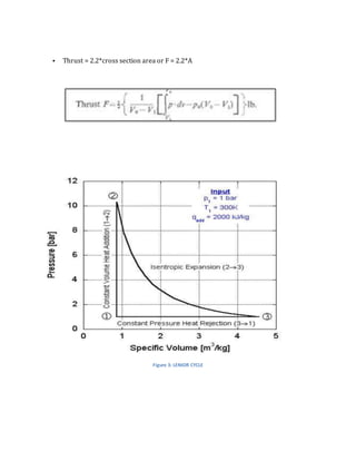
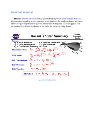
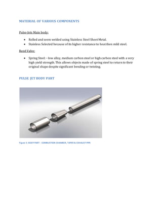
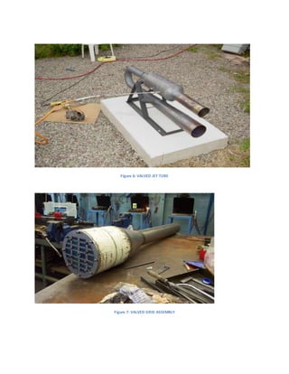
(SHREYA) Chakan Call Girls Just Call 7001035870 [ Cash on Delivery ] Pune Esc...
PULSE JET ENGINE
1. Table of Contents
PULSE JET ENGINE.....................................................................................................................................................................2
INTRODUCTION .....................................................................................................................................................................2
TYPE OF PULSE JET ENGINE........................................................................................................................................2
DESIGN RESEARCH ...............................................................................................................................................................4
IMPORTANT FORMULAE ...................................................................................................................................................6
MATERIAL OF VARIOUS COMPONENTS .....................................................................................................................7
PULSE JET BODY PART .......................................................................................................................................................7
PROJECT FUTURE ..................................................................................................................................................................9
REFERENCES ...........................................................................................................................................................................9
Table of figures
Figure 1: VALVED PULSE JET ................................................................................................................................................3
Figure 2: VALVELESS PULSE JET .........................................................................................................................................4
Figure 3: LENIOR CYCLE..........................................................................................................................................................5
Figure 4: THRUST GENERATION .........................................................................................................................................6
Figure 5: BODY PART - COMBUSTION CHAMBER, TAPER & EXHAUST PIPE ..................................................7
Figure 6: VALVED JET TUBE ..................................................................................................................................................8
Figure 7: VALVED GRID ASSEMBLY ...................................................................................................................................8
Figure 8: VALVED GRID ...........................................................................................................................................................9
2. PULSE JET ENGINE
INTRODUCTION
A pulsejet engine is a very simple jet engine consisting of no moving parts. The combustion
cycle comprises five or six phases: Induction, Fuel Injection, Ignition, Combustion, and
Exhaust.
The rapidly expanding gasses exit out of the engine and as this happens a vacuum is
created in the combustion chamber which pulls in a fresh new air charge from the
atmosphere, and then the whole cycle repeats itself.
TYPE OF PULSE JET ENGINE
There are two main types of pulsejet engines, both of which use resonant combustion and
harness the expanding combustion products to form a pulsating exhaust jet which
produces thrust intermittently.
VALVED PULSE JET
Valved pulsejet engines use a mechanical valve to control the flow of expanding
exhaust, forcing the hot gas to go out of the back of the engine through the
tailpipe only, and allow fresh air and more fuel to enter through the intake.
The valved pulsejet comprises an intake with a one-way valve arrangement. The
valves prevent the explosive gas of the ignited fuel mixture in the combustion
chamber from exiting and disrupting the intake airflow, although with all
practical valved pulsejets there is some 'blowback' while running statically and
at low speed, as the valves cannot close fast enough to stop all the gas from
exiting the intake. The superheated exhaust gases exit through an acoustically
resonant exhaust pipe.
The intake valve is typically a reed valve. The two most common configurations
are the daisy valve, and the rectangular valve grid. A daisy valve consists of a
thin sheet of material to act as the reed, cut into the shape of a stylized daisy
with "petals" that widen towards their ends. Each "petal" covers a circular intake
hole at its tip. The daisy valve is bolted to the manifold through its center.
Although easier to construct on a small scale, it is less effective than a valve grid.
3. VALVELESS PULSE JET
Valveless pulsejet engines have no moving parts and use only their geometry to
control the flow of exhaust out of the engine. Valveless pulsejets expel exhaust
out of both the intakes and the exhaust, though most try to have the majority of
exhaust go out of the longer tail pipe for more efficient propulsion.
The valveless pulsejet operates on the same principle as the valved pulsejet, but
the 'valve' is the engine's geometry. Fuel, as a gas or atomized liquid spray, is
either mixed with the air in the intake or directly injected into the combustion
chamber. Starting the engine usually requires forced air and an ignition sour ce,
such as a spark plug, for the fuel-air mix. With modern manufactured engine
designs, almost any design can be made to be self-starting by providing the
engine with fuel and an ignition spark, starting the engine with no compressed
air. Once running, the engine only requires input of fuel to maintain a self-sustaining
combustion cycle.
Figure 1: VALVED PULSE JET
4. Figure 2: VALVELESS PULSE JET
DESIGN RESEARCH
• The Lenoir cycle is an idealized thermodynamic cycle often used to model a pulse-jet
engine.
• Comprises of 3 cycles:
▫ Heat added at constant volume.
▫ Adiabatic Expansion.
▫ Exhaust of the hot gasses at a constant pressure.
• Thrust can be directly calibrated on the basis that the cycle is completed over two
working strokes.
5. • Thrust = 2.2*cross section area or F = 2.2*A
Figure 3: LENIOR CYCLE
6. IMPORTANT FORMULAE
Thrust is a reaction force described quantitatively by Newton's second and third laws.
When a system expels or accelerates mass in one direction, the accelerated mass will cause
a force of equal magnitude but opposite direction on that system. The force applied on a
surface in a direction perpendicular or normal to the surface is called thrust.
Figure 4: THRUST GENERATION
7. MATERIAL OF VARIOUS COMPONENTS
Pulse-Jets Main body:
Rolled and seem welded using Stainless Steel Sheet Metal.
Stainless Selected because of its higher resistance to heat then mild steel.
Reed Valve:
Spring Steel: - low alloy, medium carbon steel or high carbon steel with a very
high yield strength. This allows objects made of spring steel to return to their
original shape despite significant bending or twisting.
PULSE JET BODY PART
Figure 5: BODY PART - COMBUSTION CHAMBER, TAPER & EXHAUST PIPE
9. Figure 8: VALVED GRID
PROJECT FUTURE
Continue testing on prototype to gain further knowledge of its operating cycle.
Use larger engine to power to propel a manned vehicle.
REFERENCES
https://in.search.yahoo.com/yhs/search?hspart=aztec&hsimp=yhs-default&
type=ds_128_476&p=VALVELESS+PULSE+JET&rnd=591221750¶m1=
sid%3D476%3Aaid%3D128%3Aver%3D14591%3Atm%3D543%3Asrc%3Dds%3
Alng%3Den%3Aitype%3Dn%3Auip%3D2001883153
https://www.youtube.com/watch?v=bKHz7wOjb9w
http://www.colinfurze.com/jet-bicycle.html#