SlideShare a Scribd company logo
1 of 19
Download to read offline
Dept of IT | III YEAR | V SEMESTER IT E51 | COMPUTER HARDWARE AND TROUBLESHOOTING | UNIT 3
1 |Prepared By : Mr. PRABU.U/AP |Dept. of Computer Science and Engineering | SKCET |
UNIT III
Peripheral Devices & Display Adapters: Functional descriptions of keyboard – Mouse
– Printers – Joystick – Scanners – CGA – SVGA.
3.1 FUNCTIONAL DESCRIPTIONS OF KEYBOARD
3.1.1 Keyboard
A computer keyboard is a peripheral device that is designed for the input of text
and characters and also to control the operations of a computer.
3.1.2 Classification of Keys
The keys on computer keyboard are often classified as follows:
 Alphanumeric keys
 Punctuation keys
 Special keys
3.1.3 Keyboard Layouts:
The four keyboard layouts used for most desktop PCs are as follows:
 83-key PC/XT keyboard
 84-key AT keyboard
 Enhanced 101-key keyboard
 Windows 104- key keyboard
3.1.4 Keyboard Connectors:
PC keyboards connect to the motherboard on the computer using one of three
connectors. They are:
 The 5-pin DIN Connector
 The 6-pin MINI DIN Connector
 The USB Connector
1. The 5-pin DIN Connector:
A 5-PIN DIN connector is the oldest of the keyboard connector that was
originally standardized by the Deutsche Industrie Norm (DIN), the German national
standards organization. The connector is ½ inch in diameter with five pins arranged in a
semicircular pattern.
Figure 3.1: The 5-pin DIN Connector
Pin 1 Keyboard Clock CLK
Pin 2 Keyboard Data Data
Pin 3 Unused Unused
Pin 4 Ground GND
Pin 5 +5V power Vcc
Dept of IT | III YEAR | V SEMESTER IT E51 | COMPUTER HARDWARE AND TROUBLESHOOTING | UNIT 3
2 |Prepared By : Mr. PRABU.U/AP |Dept. of Computer Science and Engineering | SKCET |
2. The 6-pin MINI-DIN Connector:
The 6-pin MINI-DIN Connector also called as PS/2 connector is smaller than the
5-Pin DIN and this is the 5/16 inch in diameter. This mini-Din connector is designed to
use six pins arranged in a circular pattern. Here mostly the two unused pins are omitted
from keyboard connectors.
Figure 3.2: The 6-pin MINI-DIN Connector
3. USB Connector:
Universal Serial Bus (USB) is a serial bus standard to interface devices to a host
computer. USB was designed to allow many peripherals to be connected using a single
standardized interface socket and to improve the Plug and play capabilities by allowing
hot swapping, that is, by allowing devices to be connected and disconnected without
rebooting the computer or turning off the device.
Figure 3.3: The USB trident logo
3.1.5 Keyboards switch Types:
1. Pure mechanical switches:
The most basic mechanical switch design is one which depressing the key forces
metal contacts together, completing the circuit.
2. Foam element switches:
Similar to pure mechanical switches in so far they use an electric circuit between
each key and the circuit board below a spring to pop the key back up.
3. Rubber-dome switches:
In this design each key is sits on a top rubber dome with an electric contact on its
concave underside. The shape of the dome then forces the key back up into its original
position.
4. Membrane switches:
Similar to rubber-dome switches, except the keytop are all joined into a solid
sheet that rest on top of the rubber domes. This provides s a greater amount of
protection against the outside environment.
Pin 1 Keyboard Data Data
Pin 2 Not connected Not connected*
Pin 3 Ground GND
Pin 4 +5V power Vcc
Pin 5 Keyboard Clock CLK
Pin 6 Not connected Not connected**
Dept of IT | III YEAR | V SEMESTER IT E51 | COMPUTER HARDWARE AND TROUBLESHOOTING | UNIT 3
3 |Prepared By : Mr. PRABU.U/AP |Dept. of Computer Science and Engineering | SKCET |
3.1.6 Keyboard Operation:
Figure 3.4: Functional block Diagram of keyboard
 When a key is pressed on the keyboard, it sends control signal to the keyboard
controller.
 The keyboard controller generates a code called scan code corresponding to the
signal received.
 This code is placed in the keyboard buffer and it sends interrupt signal to the
CPU through the system software.
 The CPU stops its current execution and reads the scan code from the keyboard
buffer.
 Then it converts the scan code into its ASCII form.
3.1.7 Types of Keyboards:
1. Dome-switch keyboard
Dome-switch keyboards are kind of a hybrid of membrane and mechanical
keyboards. They bring two circuit board traces together under a rubber "dome" or
bubble. The inside of the top of the bubble is coated in some conductive substance.
2. Capacitive keyboard
In this type of keyboard, pressing the key changes the capacitance of a pattern
printed on a PC board. Usually this permits a pulse or pulse train to be sensed. Unlike
"dome switch" keyboards, the pattern will be covered by a thin, insulating film.
3. Mechanical-switch keyboard
Mechanical-switch keyboards use real switches, one under each key. Depending
on the construction of the switch, these keyboards have varying responses and travel
times.
4. Buckling-spring keyboard
 It is a common misconception that the IBM Model M and its derivates are
mechanical-switch keyboards.
 In fact, the Model M uses membrane-sheet switches, much like those found in a
dome-switch keyboard.
 The buckling spring mechanism atop the switch is responsible for the tactile and
aural response of the keyboard.
 This mechanism controls a small hammer that strikes the membrane switch. For
more information, see an examination of buckling-spring technology.
Keyboard
Keyboard
controller
CPU
Keyboard
buffer
System
software
Dept of IT | III YEAR | V SEMESTER IT E51 | COMPUTER HARDWARE AND TROUBLESHOOTING | UNIT 3
4 |Prepared By : Mr. PRABU.U/AP |Dept. of Computer Science and Engineering | SKCET |
5. Hall-effect keyboard
Hall effect keyboards use magnets and Hall effect sensors instead of an actual
switch. When a key is depressed, it moves a magnet, which is detected by the solid-state
sensor. These keyboards are extremely reliable, and are able to accept millions of
keystrokes before failing.
6. Laser keyboard
A laser projection device approximately the size of a computer mouse projects
the outline of keyboard keys onto a flat surface, such as a table or desk. When the laser
is interrupted in the position of a key, a keystroke is registered.
7. Membrane keyboard
Membrane keyboards are usually flat. They are most often found on appliances
like microwave ovens or photocopiers. A common design consists of three layers. The
top layer (and the one the user touches) has the labels printed on its front and
conductive stripes printed on the back.
3.2 MOUSE
3.2.1 Functional Description of Mouse
 Mouse is a graphical input device.
 This is used to control the cursor movement on the screen by moving it over a
flat surface.
 It contains two or three buttons on the top.
 When the user presses one of the buttons, the mouse either marks a location
on the screen or makes selection from data on the screen.
 This can also be used in combination with a keyboard.
3.2.2 Classification of Operations on Mouse
 The operations on a mouse can be classified into three types. They are
 Click
 Double click
 Drag
 To click on an item means to move the mouse pointer to the item on the screen
and to press and release the mouse button once.
 To double-click on an item means to moue the mouse pointer to the item on the
screen and to press and release the mouse button twice in rapid succession.
 To drag an item, keep the mouse pointer over the item, then press the mouse
button and move the mouse. Release the button after placing the item placing
destination position.
3.2.3 Types of Mouse
There are three types of mouse interface. They are,
i) Serial mouse
ii) Bus mouse
iii) PS/2 mouse
1. Serial Mouse:
A serial mouse is connected to the RS232C Serial Port of the system using a 9-pin
or 25-pin female connector.
Dept of IT | III YEAR | V SEMESTER IT E51 | COMPUTER HARDWARE AND TROUBLESHOOTING | UNIT 3
5 |Prepared By : Mr. PRABU.U/AP |Dept. of Computer Science and Engineering | SKCET |
2. Bus Mouse:
In certain circumstances the serial mouse or the PS/2 mouse cannot be
connected to the system (com port). In such case bus mouse is used. It has a stand-alone
mouse controller board. It is connected to the system using a 9-pin male DIN connector.
3. PS/2 Mouse:
 Now-a-days, computers are fitted with one or two PS/2 ports.
 PS/2 mouse uses a 6-pin DIN connector.
 In this, the CLK and DATA lines will control the bi-directional data transmission.
 The below table shows the signals used in PS/2 mouse.
Pin No. Signals
1 Data
2 Reserved
3 Ground
4 +5V
5 Clk
6 Reserved
Shield Chassis
3.2.4 Working of a Mouse:
The mouse is made up of plastic with one or more switches on the top and ball
bearing on its lower surface.
Figure 3.5: Working of a Mouse

 The ball bearing allows the users to move the mouse in any direction.
 On two sides of the ball, at a 90-degree angle. There are two small rollers that
touch the ball. This rollers spins when the ball rolls and sense the X and Y
direction movements.
 A sensor detects how much each roller spins and sends this information to the
computer.
 The computer translates the information and changes the position of the screen
pointer to correspond to the position indicated by the mouse.
Dept of IT | III YEAR | V SEMESTER IT E51 | COMPUTER HARDWARE AND TROUBLESHOOTING | UNIT 3
6 |Prepared By : Mr. PRABU.U/AP |Dept. of Computer Science and Engineering | SKCET |
 Like the keyboard, a mouse does not actually sense a message directly to the
program that the computer is running.
 Rather, it sends an interrupt request to the CPU.
 The program that is running checks regularly to see whether the mouse has been
used.
 If it was used, the program acts according to the interrupt given by the system.
3.2.5 Connection:
The mouse is connected to the system in two ways. They are,
1. through a 9-pin DIN connector of the Port Com1 or Port Com2.
2. through a PS/2 Socket.
Depending on the structure of the cable and the mouse will be either connected to the
Port Com1 or the PS/2 connector.
3.2.6 Mouse signals:
The table below shows the signals at the connector.
Pin No. Signal Direction
1. DCD – Data Carrier Detect From mouse to PC
2. RX – Receive Data From mouse to PC
3. TX – Transmit Data From PC to mouse
4. DTR – Data Terminal Ready From PC to mouse
5. GND – Ground Common Signal
6. DSR – Data Set Ready From mouse to PC
7. RTS – Request To Send From PC to mouse
8. CTS – Clear To Send From mouse to PC
9. RI – Ring Indicator From mouse to PC
3.2.7 Installation of Mouse:
To install a mouse follow the steps given below.
1. Switch off the system.
2. Connect the mouse cable end to the Port Com1 or PS/2 as per the option provided.
3. Restart the computer.
4. In the Win 95/98 and above versions it will be auto detected.
5. Otherwise put the device driver disk to install the software.
 The device driver software is supplied by manufacture in a floppy disk.
 The following command line has to be added in the CONFIG.SYS file.
DEVICE = C:MOUSE.SYS
 Otherwise the following line is to be included in the AUTOEXEC.BAT
C:MOUSE.COM
This will make the mouse installation completed.
3.3 PRINTER
 The printer is an electromechanical device. It has both electronic circuits and
mechanical assemblies.
 The electronics circuits control the mechanical assemblies.
 Hence the electronic circuits in a printer are usually referred to as printer
electronics or control electronics.
Dept of IT | III YEAR | V SEMESTER IT E51 | COMPUTER HARDWARE AND TROUBLESHOOTING | UNIT 3
7 |Prepared By : Mr. PRABU.U/AP |Dept. of Computer Science and Engineering | SKCET |
Computer
Interface
Figure 3.6: Printer Block Diagram
3.3.1Printer Functions
 The printer receives data characters from the computer and prints the
characters on the paper.
 In addition, the printer also receives control characters from the computer. The
control characters are not printable characters.
 They convey some sort of control information to the printer.
 Some of the control characters widely used are
 CR(Carriage Return)
 LF(Line Feed) and
 FF(Form Feed)
3.3.2 Printer Characteristics
The main characteristics of printer are listed below:
1. SPEED specified as CPS(Characters Per Second), LPM(Lines Per Minute) or PPM
(Pages Per Minute). It indicates how fast a printer works.
2. QUALITY specified as DRAFT, NLQ(Near Letter Quality) or LQP(Letter Quality
Printer). This implies how good the shape of the printer character is.
3. CHARACTER SET indicating the total number of data characters and control
characters recognised by the printer.
4. INTERFACE specifying whether the printer receives characters from the printer in
parallel form(one character at a time) or in serial form(one bit at a time).
5. BUFFER SIZE indicating how many data characters can be stacked in the printer
buffer memory before printing.
6. PRINT MECHANISM specified as impact dot matrix, impact daisy wheel, impact golf
ball, electrosensitive dot matrix, thermal dot matrix, band, belt, drum, train, chain, ink
jet or laser.
7. PRINT MODE specified as serial or parallel
8. PRINT SIZE specified as character size and number of characters per line.
9. PRINT DIRECTION specified as unidirectional, reverse, bidirectional logic seeking.
3.3.3 Printer Modules
The modules inside a printer are:
1. Print-head mechanism.
2. Carriage-movement mechanism.
3. Paper-feed mechanism.
4. Control electronics.
Control and Sense signals
Computer Printer
Electronics
Mechanical
Assemblies
Paper
Dept of IT | III YEAR | V SEMESTER IT E51 | COMPUTER HARDWARE AND TROUBLESHOOTING | UNIT 3
8 |Prepared By : Mr. PRABU.U/AP |Dept. of Computer Science and Engineering | SKCET |
5. Interface logic.
6. Power supply.
3.3.4 Printer Types
1. Impact and Non-Impact Printer
In an impact printer, the character is formed by physical(or) pressure of the
print head(hammer, pin or font) against an ink and onto paper. The dot matrix printer,
daisy wheel printer, golf-ball printer, drum printer, band printer and chain printer are
all impact printers.
 The Dot matrix impact printer
The dot matrix printer does not print a whole character. Each character is
formed by small dots. A matrix, usually a 7 by 5, is followed to create the
character pattern of dots. The print head consists of pins arranged in a vertical
column.
 Daisy wheel printer
In a daisy wheel printer, the print head consists of a circular wheel. There
are 96 spokes or character arms on the wheel. Each spoke has a raised
character(print block) marked at the tip. The print quality of a daisy-wheel
printer is very good.
 Golf-Ball printer
In the golf-ball printer, there is a spherical golf-ball like metallic unit. The
different characters are marked on the golf-ball, as a raised type around a
sphere. To print a character, the drive mechanism causes appropriate movement
of the ball, so that character to be printed is brought in front of the desired
position on the paper. The print quality of a golf-ball printer is excellent.
In a non-impact printer, there is no physical contact of the head with the paper
or ribbon. The laser printer, thermal printer, ink jet printer and electrostatic printer are
all non-impact printers.
 The Laser printer
The laser printer operates much like a xerox machine. A laser is used to
create an image on a photosensitive drum. For this purpose, the laser is turned
on and off, when it sweeps back and forth across the drum. Laser printer offers
both letter quality and speed.
 Thermal printer
Usually, thermal printers use special heat sensitive paper. The print head
consists of heating elements. The character are printed as a matrix of dots. When
a particular heating element is switched ON, the corresponding spot on the paper
is heated and the spot turns dark. Thus spots are burnt onto the paper thereby
creating characters or graphics. The thermal printer is quiet and print quality is
consistent.
 Ink jet printer
Ink jet printer provides better quality print out than dot matrix printer.
Its output is sharp though not to the same level as a laser printer's output. Still it
is very cheap compared to a laser printer.
Dept of IT | III YEAR | V SEMESTER IT E51 | COMPUTER HARDWARE AND TROUBLESHOOTING | UNIT 3
9 |Prepared By : Mr. PRABU.U/AP |Dept. of Computer Science and Engineering | SKCET |
2. Character printer and Line printer
Character printer
In a character printer, characters are printed one after the other. Only one
character can be printed at a time. The character printer is also known as serial printer.
The daisy wheel printer and dot matrix printer are examples of character printer.
Line printer
In a line printer, many characters of a line are printed at a time. To an user, the
line printer appears to print a complete line of character in one shot. The drum printer,
band printer and chain printer are examples of line printers.
3. Draft, LQP and NLQ printers
Draft printer
In a draft quality printer, the printer character is formed by closely spaced dots,
creating character shape. Though the character is visible, it is not impressive because of
the presence of dots. The dot matrix printer is an example of a draft printer.
LQP(Letter Quality Printer)
In a LQP a whole character is formed as a letter(without dots), like a typewriter.
It is pleasant to read and hence LQP is widely used in office environments. The daisy
wheel printer is an example of a letter quality printer.
NLQ(Near Letter Quality Printer)
A NLQ printer also prints characters as patterns of dots. But each character is
printed twice. The heads(dots) are offset by a minute distance during the second time.
4. Parallel interface and serial interface printer
Parallel interface printer
In a parallel interface printer, the printer receives all 8 bits of a character
simultaneously from the computer. Hence there are 8 data lines between the computer
and printer.
Serial interface printer
In a serial interface printer, the printer receives the 8 bits of character one after
the other, in a serial fashion. There is only one data line between the computer and
printer.
5. Unidirectional and bidirectional printers
Unidirectional printer
In an unidirectional printer, the printing is performed only when the print head
moves in one direction, i.e., from left to right. This is similar to a manual typewriter
operation.
Bidirectional printer
In a bidirectional printer, printing is performed during both directions of the
head movement. If one line is printed when the head moves from left to right, the next
line is printed when the print head moves from right to left. The print speed of a
bidirectional printer is more than the speed of an unidirectional printer.
Dept of IT | III YEAR | V SEMESTER IT E51 | COMPUTER HARDWARE AND TROUBLESHOOTING | UNIT 3
10 |Prepared By : Mr. PRABU.U/AP |Dept. of Computer Science and Engineering | SKCET |
3.4 JOYSTICK
 A joystick is a pointing device that moves in all directions and controls the
movement of a pointer.
 A joystick is similar to a mouse, except that with a mouse the cursor stops
moving as soon as you stop moving the mouse.
 With a joystick, the pointer continues moving in the direction the joystick is
pointing.
 To stop the pointer, you must return the joystick to its upright position.
 Joysticks are used mostly for computer games
 Pressure of stick = velocity of movement
 It is also known as the control column
 Joysticks are also used for controlling machines such as cranes, trucks,
underwater unmanned vehicles, wheelchairs, surveillance cameras, and zero
turning radius lawn mowers.
3.4.1 History:
 The name "joystick" is thought to originate with early 20th century French pilot
Robert Esnault-Pelterie.
 Joysticks were commonly used as controllers in first and second generation
game consoles, but then gave way to the familiar Game pad with the Nintendo
Entertainment System and Sega Master System in 1985 and 86, though joysticks
- especially arcade-style ones - were and are popular after-market add-ons for
any console.
 More recently, analog sticks have become standard on video game consoles and
have the ability to indicate the stick's displacement from its neutral position.
 This means that the software does not have to keep track of the position or
estimate the speed at which the controls are moved.
Figure 3.7:Typical diagram of a joystick
3.4.2 Joystick Overview
 Joysticks consist of a base and a stick that can be moved in any direction.
 The stick can be moved slowly or quickly and in different amounts.
 Some joysticks have sticks that can also be rotated to the left or right.
 Because of the flexible movements a joystick allows, it can provide much greater
control than the keys on a keyboard.
 Joysticks typically include several buttons.
 Most joysticks have at least one button on the top of the stick and another button in
the front of the stick for the trigger.
Dept of IT | III YEAR | V SEMESTER IT E51 | COMPUTER HARDWARE AND TROUBLESHOOTING | UNIT 3
11 |Prepared By : Mr. PRABU.U/AP |Dept. of Computer Science and Engineering | SKCET |
Figure 3.7: Typical diagram of a Joystick
Joystick elements:
1. Stick
2. Base
3. Trigger
4. Extra buttons
5. Autofire switch
6. Throttle
7. Hat Switch
8. Suction Cup
3.4.3 Technical Details
 An analog joystick is a joystick which has continuous states, i.e. returns an angle
measure of the movement in any direction in the plane or the space (usually
utilizing potentiometers) and a digital joystick gives only on/off signals for four
different directions, and mechanically possible combinations (such as up-right,
down-left) (Digital joysticks were very common as game controllers for the video
game consoles, arcade machines, and home computers of the 1980s.)
 Additionally joysticks often have one or more fire buttons, used to trigger some
kind of action. These are simple on/off switches.
 Some joysticks have force feedback capability. These are thus active devices, not
just simple input devices.
 The computer can return a signal to the joystick that causes it to resist the
movement with a returning force or make the joystick vibrate
3.4.4 Types
1.Digital Joysticks
 Digital joysticks are the most common joysticks used for PCs, employing simple
left, right, up, down and firing commands.
 Digital joystick gives only on/off signals for four different directions
2.Paddle Joysticks
 Paddle joysticks consist of one knob used to control the game and one firing
button.
Dept of IT | III YEAR | V SEMESTER IT E51 | COMPUTER HARDWARE AND TROUBLESHOOTING | UNIT 3
12 |Prepared By : Mr. PRABU.U/AP |Dept. of Computer Science and Engineering | SKCET |
 This is one of the oldest joysticks, as it was first introduced with the very first
home video game consoles.
3.Analog Joysticks
 Analog joysticks combine both concepts presented in the digital and paddle
joysticks;
 they control the game like a digital joystick, but also use to measure the
movements like the paddle joysticks.
 An analogue joystick is a joystick which has continuous states of the movement
in any direction in the plane
4.PC Analog Joysticks
 IBM first presented this joystick with their personal computer. It's a simple
analog-styled joystick with multiple buttons that usually connects via an USB
port.
5.Joypads
 Joypads are joysticks without the sticks.
 Instead, they employ a directional pad (D-pad) to control the game.
 Joypads are considered a bit primitive, but they are still featured among the
current video game controllers.
3.4.5 Working of Joysticks
 A joystick is a personal computer peripheral or general control device consisting
of a handheld stick that pivots about one end and transmits its angle in two or
three dimensions to a computer.
 Most joysticks are two-dimensional, having two axes of movement (similar to a
mouse), but three-dimensional joysticks do exist. A joystick is generally
configured so that moving the stick left or right signals movement along the X
axis, and moving it forward (up) or back (down) signals movement along the Y
axis.
 In joysticks that are configured for three-dimensional movement, twisting the
stick left (counter-clockwise) or right (clockwise) signals movement along the Z
axis. These three axes - X Y and Z - are, in relation to an aircraft, roll, pitch, and
yaw.
 Joysticks are often used to control video games, and usually have one or more
push-buttons whose state can also be read by the computer.
 The term joystick has become a synonym for game controllers that can be
connected to the computer since the computer defines the input as a "joystick
input".
 Apart from controlling games, joysticks are also used for controlling machines
such as aircraft, cranes, trucks, powered wheelchairs.
3.5 SCANNER
 A scanner is an input device that scans documents such as photographs and
pages of text.
 When a document is scanned, it is converted into a digital format.
 Scanners come in black-and-white, or color.
 When a document is placed inside a scanner, the image is first scanned and then
the scanned data is processed and sent to a computer system.
Dept of IT | III YEAR | V SEMESTER IT E51 | COMPUTER HARDWARE AND TROUBLESHOOTING | UNIT 3
13 |Prepared By : Mr. PRABU.U/AP |Dept. of Computer Science and Engineering | SKCET |
 Scanners can read red-green-blue color from color array.
 Image resolution is measured in pixels per inch.
3.5.1 Types of scanners
There are different types of scanners for different types of documents that need
to be scanned.
 Flatbed Scanners
 Sheet-fed Scanners
 Handheld Scanners
 Drum Scanners
 Integrated Scanners
 Smartphone Scanners
1.Flatbed Scanner
 Used for scanning most documents, photos, and even flat objects from a PC or
laptop.
 Flatbed scanner works like a copy machine.
 Scans documents placed face down on the glass (scan bed)
 Most common type of scanner.
2.Sheet-fed Scanner
 More portable than a flatbed scanner.
 Used to scan paper documents and photos.
 The paper moves through the scanner.
 Usually smaller than a flat-bed and portable.
3.Handheld Scanner
 Smaller than the previous two scanners.
 The user must move the scanner across the document.
 Image quality us usually lower.
4.Drum Scanner
 Used by the publishing industry.
 Document is placed on a glass cylinder.
 Generates very high quality scans.
 These scan an image with photomultiplier tubes (PMT).
5.Integrated Scanners
 Modern types of scanners when it comes to obtaining images. ATMs feature this
type of built-in scanner for check-processing and approval.
6.Smartphone Scanners
 Apps can be downloaded on many smart phone devices, allowing them to scan
documents through the digital camera exposures and provide output in JPEG or
PDF formats.
Dept of IT | III YEAR | V SEMESTER IT E51 | COMPUTER HARDWARE AND TROUBLESHOOTING | UNIT 3
14 |Prepared By : Mr. PRABU.U/AP |Dept. of Computer Science and Engineering | SKCET |
3.5.2 Using Your Scanner
 Most flatbed scanners are connected to the computer via the Universal Serial Bus
(USB).
 A software program called a TWAIN driver is used by the computer to
communicate with the scanner.
 Most modern Scanners connect to the computer through the USB.
3.5.3 Scanner Software
 The TWAIN is a standard of communication between the computer and scanner
that all scanner manufacturers agree to that allow images to be directly scanned
from an image editing program.
 The TWAIN driver controls the scanner and serves as the interface between the
scanner and your graphics program.
3.5.4 Scanning a Photo
 The image to be scanned should be placed face down on the scanning bed.
 The scanner will have a marker indicating where the top of the image should go.
3.5.5 Scanning Formats
 Depending on your scanning software, you may have different options of file
formats in which to save your scanned image or document.
 Images may be saved as:
 jpg, bmp, tif, or png.
 Documents may be saved as:
 pdf, or any of the image formats
.bmp
 The BMP file format, sometimes called bitmap file format , is an image file
format used to store bitmap digital images.
 doesn't support color management
.tif
 Tagged Image File Format (abbreviated TIFF) is a file format for storing
images, including photographs and line art.
 tif images are considered lossless, meaning when compressed they do not lose
any of the data
.jpg
 jpg is the most common image format used by digital cameras and other
photographic image capture devices, and is the most common format for storing
and transmitting photographic images on the World Wide Web.
 jpg images are considered lossy, meaning when compressed, they lose some of
the data
.pdf
 The Portable Document Format (PDF) is the file format created by Adobe
Systems in 1993 for document exchange.
3.5.6 After Scanning
 After scanning, you may need to modify your image in a graphic editing program.
 Crop
 Brightness
 Contrast
Dept of IT | III YEAR | V SEMESTER IT E51 | COMPUTER HARDWARE AND TROUBLESHOOTING | UNIT 3
15 |Prepared By : Mr. PRABU.U/AP |Dept. of Computer Science and Engineering | SKCET |
Crop
 To crop an image means to cut away, or trim, the image.
Brightness
 Refers to the lightness and darkness of a color.
 Also referred to as tone or value.
Contrast
 Contrast is the difference in visual properties that makes an object (or its
representation in an image) distinguishable between other objects and the
background.
3.6 COLOR GRAPHICS ADAPTER
The Color Graphics Adapter (CGA), introduced in 1981, was IBM's first color
graphics card (originally sold under the name "Color/Graphics Monitor Adapter"), and
the first color computer display standard for the IBM PC.
3.6.1 The CGA color palette
'''Full CGA 16-color palette'''
0 — black
#000000
8 — (dark) gray
#555555
1 — blue
#0000AA
9 — bright blue
#5555FF
2 — green
#00AA00
10 — bright green
#55FF55
3 — cyan
#00AAAA
11 — bright cyan
#55FFFF
4 — red
#AA0000
12 — bright red
#FF5555
5 — magenta
#AA00AA
13 — bright magenta
#FF55FF
6 — brown
#AA5500
14 — yellow
#FFFF55
7 — white (light gray)
#AAAAAA
15 — bright white
#FFFFFF
3.6.2 Standard text modes
CGA offers two text modes:
1. 40×25 characters
 It supports up to 16 colors.
Dept of IT | III YEAR | V SEMESTER IT E51 | COMPUTER HARDWARE AND TROUBLESHOOTING | UNIT 3
16 |Prepared By : Mr. PRABU.U/AP |Dept. of Computer Science and Engineering | SKCET |
 Each character was a pattern of 8×8 dots. The effective screen resolution in this
mode was 320×200 pixels (a pixel aspect ratio of 1:1.2), though individual pixels
could not be addressed independently.
 The choice of patterns for any location was thus limited to one of the 256
available characters, the patterns for which were stored in a ROM chip on the
card itself.
 The display font in text mode was therefore fixed and could not be changed
(although when using the original IBM CGA in an original IBM PC it was possible
to select one of two different fonts—normal or thin—by changing a jumper.
 The card had sufficient video RAM for 8 different text pages in this mode.
2. 80×25 characters
 It supports up to 16 colors.
 Each character was again an 8×8 dot pattern (the same character set was used as
for 40×25), in a pixel aspect ratio of 1:2.4.
 The effective screen resolution of this mode was 640×200 pixels.
 Again, the pixels could not be individually addressed.
 Since there were twice as many characters on the screen in this mode, the card
had enough video RAM just for 4 different text pages.
3.6.3 Standard RGB graphics modes
CGA offered two commonly-used graphics modes:
 320×200 pixels, as with the 40×25 text mode. In the graphics mode, however,
each pixel could be addressed independently. The trade-off was that only 4
colors could be displayed at a time. These four colors could not be freely chosen
from the 16 CGA colors — there were only two official palettes for this mode:
1. Magenta, cyan, white and background color (black by default).
2. Red, green, brown/yellow and background color (black by default).
 640×200 pixels, as with the 80×25 text mode. All pixels could be addressed
independently. This mode was monochrome, offering only black and white as
colors (though this could be changed), with a pixel aspect ratio of 1:2.4.
Fixed CGA 4-color palette #1
default 5 — magenta
3 — cyan 7 — white (light gray)
Fixed CGA 4-color palette #2
default 4 — red
2 — green 6 — brown (orange)
Dept of IT | III YEAR | V SEMESTER IT E51 | COMPUTER HARDWARE AND TROUBLESHOOTING | UNIT 3
17 |Prepared By : Mr. PRABU.U/AP |Dept. of Computer Science and Engineering | SKCET |
3.6.4 Specifications
Connector:
Figure 3.8: DE-9 Connector
Pin assignments
Pin Function
1 Ground
2 Ground
3 Red
4 Green
5 Blue
6 Intensity
7 Reserved
8 Horizontal Sync
9 Vertical Sync
Figure 3.9: Pin Assignments
Signal:
Type Digital, TTL
Resolution 640h × 200v, 320h × 200v
H-freq 15.75 kHz
V-freq 60 Hz
Colors 16
Figure 3.10: Signal
3.6.5 Competing adapters
CGA had two main competitors:
1. Monochrome Display Adapter (MDA)
 For business and word processing use, IBM launched its Monochrome Display
Adapter (MDA) at the same time as CGA.
 The MDA produced a higher resolution text display in 80×25 mode, rendering
each character in a box of 9×14 pixels, of which 7×11 were the character itself.
 This produced sharper characters than the CGA's 8×8 dots text character matrix
allowed.
 Because of this and CGA's higher price at the time, MDA was often preferred for
business use.
Dept of IT | III YEAR | V SEMESTER IT E51 | COMPUTER HARDWARE AND TROUBLESHOOTING | UNIT 3
18 |Prepared By : Mr. PRABU.U/AP |Dept. of Computer Science and Engineering | SKCET |
2. Hercules Graphics Card (HGC)
 In 1982, the non-IBM Hercules Graphics Card (HGC) was introduced.
 In addition to an MDA-compatible text mode, it offered a monochrome graphics
mode. With a resolution of 720×348 pixels, the graphics mode was better than
what CGA could produce.
 The Hercules adapter's offer of better monochrome graphics and its ability to
work with less expensive monochrome monitors made it a desirable choice for
many.
3.7 SUPER VIDEO GRAPHICS ARRAY
Super Video Graphics Array, almost always abbreviated to Super VGA or just
SVGA is a broad term that covers a wide range of computer display standards.
Figure 3.11: 15-pin D-sub port
3.7.1 SVGA Overview
 Originally, it was an extension to the VGA standard first released by IBM in 1987.
Unlike VGA—a purely IBM-defined standard—Super VGA was defined by the
Video Electronics Standards Association (VESA), an open consortium set up to
promote interoperability and define standards.
 When used as a resolution specification, in contrast to VGA or XGA for example,
the term SVGA normally refers to a resolution of 800 × 600 pixels.
3.7.2 SVGA Extension
 Super VGA was first defined in 1989. In that first version, it called for a resolution
of 800 × 600 4-bit pixels.
 Each pixel could therefore be any of 16 different colors.
 It was quickly extended to 1024 × 768 8-bit pixels, and well beyond that in the
following years.
3.7.3 SVGA Monitor
 Although the number of colors was defined in the original specification, this soon
became irrelevant as (in contrast to the old CGA and EGA standards) the
interface between the video card and the VGA or Super VGA monitor uses simple
analog voltages to indicate the desired colour depth. In consequence, so far as
the monitor is concerned, there is no theoretical limit to the number of different
colors that can be displayed.
 Note that this applies to any VGA or Super VGA monitor.
Dept of IT | III YEAR | V SEMESTER IT E51 | COMPUTER HARDWARE AND TROUBLESHOOTING | UNIT 3
19 |Prepared By : Mr. PRABU.U/AP |Dept. of Computer Science and Engineering | SKCET |
3.7.4 SVGA Card
 While the output of a VGA or Super VGA video card is analog, the internal
calculations the card performs in order to arrive at these output voltages are
entirely digital.
 To increase the number of colors a Super VGA display system can reproduce, no
change at all is needed for the monitor, but the video card needs to handle much
larger numbers and may well need to be redesigned from scratch.
 Even so, the leading graphics chip vendors were producing parts for high-colour
video cards within just a few months of Super VGA's introduction.
3.7.5 SXGA
On paper, the original Super VGA was to be succeeded by Super XGA, but in
practice the industry soon abandoned the attempt to provide a unique name for each
higher display standard, and almost all display systems made between the late 1990s
and the early 2000s are classed as Super VGA.
3.7.6 Performance
Monitor manufacturers sometimes advertise their products as XGA or Super
XGA. In practice this means little, since all Super VGA monitors manufactured since the
later 1990s have been capable of at least XGA and usually considerably higher
performance.

More Related Content

What's hot (20)

8085 interrupts
8085 interrupts8085 interrupts
8085 interrupts
 
Computer organization memory
Computer organization memoryComputer organization memory
Computer organization memory
 
Lecture 8 disk management
Lecture 8 disk managementLecture 8 disk management
Lecture 8 disk management
 
Risc & cisk
Risc & ciskRisc & cisk
Risc & cisk
 
Addressing modes of 8086
Addressing modes of 8086Addressing modes of 8086
Addressing modes of 8086
 
Microprogram Control
Microprogram Control Microprogram Control
Microprogram Control
 
Disk structure
Disk structureDisk structure
Disk structure
 
UART Communication
UART CommunicationUART Communication
UART Communication
 
Cache memory
Cache  memoryCache  memory
Cache memory
 
Timers and pwm
Timers and pwmTimers and pwm
Timers and pwm
 
Microprocessor 8086-lab-mannual
Microprocessor 8086-lab-mannualMicroprocessor 8086-lab-mannual
Microprocessor 8086-lab-mannual
 
Lesson 03
Lesson 03Lesson 03
Lesson 03
 
dual-port RAM (DPRAM)
dual-port RAM (DPRAM)dual-port RAM (DPRAM)
dual-port RAM (DPRAM)
 
x86 architecture
x86 architecturex86 architecture
x86 architecture
 
Single accumulator based CPU.pptx
Single accumulator based CPU.pptxSingle accumulator based CPU.pptx
Single accumulator based CPU.pptx
 
Subroutine
SubroutineSubroutine
Subroutine
 
X86 Architecture
X86 Architecture X86 Architecture
X86 Architecture
 
Segmentation in Operating Systems.
Segmentation in Operating Systems.Segmentation in Operating Systems.
Segmentation in Operating Systems.
 
Lecture 2
Lecture 2Lecture 2
Lecture 2
 
Memory interleaving
Memory interleavingMemory interleaving
Memory interleaving
 

Similar to Peripheral Devices & Display Adapters

Introduction to Computer System-ppt.pptx
Introduction to Computer System-ppt.pptxIntroduction to Computer System-ppt.pptx
Introduction to Computer System-ppt.pptxInfofarazMotivativeA
 
Lecture on Computer Introduction
Lecture on Computer IntroductionLecture on Computer Introduction
Lecture on Computer IntroductionCoach Spark Ovadje
 
Introduction to computer according to veta curicullum
Introduction to computer according to veta curicullumIntroduction to computer according to veta curicullum
Introduction to computer according to veta curicullumSteven Alphonce
 
Introduction to Computer System-ppt-converted.pptx
Introduction to Computer System-ppt-converted.pptxIntroduction to Computer System-ppt-converted.pptx
Introduction to Computer System-ppt-converted.pptxShivanjaliChaurasia1
 
Introduction to Computer (Guided Hypermedia)
Introduction to Computer (Guided Hypermedia)Introduction to Computer (Guided Hypermedia)
Introduction to Computer (Guided Hypermedia)Sheila Luz Gorumba
 
Input devices, Output devices , It's Types and CPU
Input devices, Output devices  , It's Types and CPUInput devices, Output devices  , It's Types and CPU
Input devices, Output devices , It's Types and CPUArpitaVajpayee
 
Input and output device
Input and output deviceInput and output device
Input and output deviceTapan Khilar
 
Random 120507151041-phpapp02
Random 120507151041-phpapp02Random 120507151041-phpapp02
Random 120507151041-phpapp02Yazeed Khalid
 
Computer hardware-peripherals compress
Computer hardware-peripherals compressComputer hardware-peripherals compress
Computer hardware-peripherals compressKefyalew Temesgen
 
Parts and Function of Computer
Parts and Function of ComputerParts and Function of Computer
Parts and Function of ComputerRhenan Belisario
 
Computer Based Presentation.pptx
Computer Based Presentation.pptxComputer Based Presentation.pptx
Computer Based Presentation.pptxShivamYadav362790
 
group1zealousdatapresentation-140821005102-phpapp02.pdf
group1zealousdatapresentation-140821005102-phpapp02.pdfgroup1zealousdatapresentation-140821005102-phpapp02.pdf
group1zealousdatapresentation-140821005102-phpapp02.pdfAldrinJosephLacuarin
 
Ch 01-types-and-components-of-computers
Ch 01-types-and-components-of-computersCh 01-types-and-components-of-computers
Ch 01-types-and-components-of-computersmmoussa83
 

Similar to Peripheral Devices & Display Adapters (20)

computerComputer
computerComputercomputerComputer
computerComputer
 
Introduction to Computer System-ppt.pptx
Introduction to Computer System-ppt.pptxIntroduction to Computer System-ppt.pptx
Introduction to Computer System-ppt.pptx
 
Lecture on Computer Introduction
Lecture on Computer IntroductionLecture on Computer Introduction
Lecture on Computer Introduction
 
chapter 2.pptx
chapter 2.pptxchapter 2.pptx
chapter 2.pptx
 
Module2 computer system
Module2 computer systemModule2 computer system
Module2 computer system
 
Introduction to computer according to veta curicullum
Introduction to computer according to veta curicullumIntroduction to computer according to veta curicullum
Introduction to computer according to veta curicullum
 
Introduction to Computer System-ppt-converted.pptx
Introduction to Computer System-ppt-converted.pptxIntroduction to Computer System-ppt-converted.pptx
Introduction to Computer System-ppt-converted.pptx
 
Introduction to Computer (Guided Hypermedia)
Introduction to Computer (Guided Hypermedia)Introduction to Computer (Guided Hypermedia)
Introduction to Computer (Guided Hypermedia)
 
Parts Of A Computer System
Parts Of A Computer SystemParts Of A Computer System
Parts Of A Computer System
 
Module2 computer system
Module2 computer systemModule2 computer system
Module2 computer system
 
Input devices, Output devices , It's Types and CPU
Input devices, Output devices  , It's Types and CPUInput devices, Output devices  , It's Types and CPU
Input devices, Output devices , It's Types and CPU
 
System Unit
System UnitSystem Unit
System Unit
 
Input and output device
Input and output deviceInput and output device
Input and output device
 
Random 120507151041-phpapp02
Random 120507151041-phpapp02Random 120507151041-phpapp02
Random 120507151041-phpapp02
 
Computer hardware-peripherals compress
Computer hardware-peripherals compressComputer hardware-peripherals compress
Computer hardware-peripherals compress
 
Parts and Function of Computer
Parts and Function of ComputerParts and Function of Computer
Parts and Function of Computer
 
Computer Based Presentation.pptx
Computer Based Presentation.pptxComputer Based Presentation.pptx
Computer Based Presentation.pptx
 
group1zealousdatapresentation-140821005102-phpapp02.pdf
group1zealousdatapresentation-140821005102-phpapp02.pdfgroup1zealousdatapresentation-140821005102-phpapp02.pdf
group1zealousdatapresentation-140821005102-phpapp02.pdf
 
mix topic.pptx
mix topic.pptxmix topic.pptx
mix topic.pptx
 
Ch 01-types-and-components-of-computers
Ch 01-types-and-components-of-computersCh 01-types-and-components-of-computers
Ch 01-types-and-components-of-computers
 

More from Prabu U

Computation Using Scipy, Scikit Image, Scikit Learn
Computation Using Scipy, Scikit Image, Scikit LearnComputation Using Scipy, Scikit Image, Scikit Learn
Computation Using Scipy, Scikit Image, Scikit LearnPrabu U
 
Concurrency and Parallelism, Asynchronous Programming, Network Programming
Concurrency and Parallelism, Asynchronous Programming, Network ProgrammingConcurrency and Parallelism, Asynchronous Programming, Network Programming
Concurrency and Parallelism, Asynchronous Programming, Network ProgrammingPrabu U
 
File Input/output, Database Access, Data Analysis with Pandas
File Input/output, Database Access, Data Analysis with PandasFile Input/output, Database Access, Data Analysis with Pandas
File Input/output, Database Access, Data Analysis with PandasPrabu U
 
Arrays with Numpy, Computer Graphics
Arrays with Numpy, Computer GraphicsArrays with Numpy, Computer Graphics
Arrays with Numpy, Computer GraphicsPrabu U
 
Lambdas, Collections Framework, Stream API
Lambdas, Collections Framework, Stream APILambdas, Collections Framework, Stream API
Lambdas, Collections Framework, Stream APIPrabu U
 
Exception handling, Stream Classes, Multithread Programming
Exception handling, Stream Classes, Multithread ProgrammingException handling, Stream Classes, Multithread Programming
Exception handling, Stream Classes, Multithread ProgrammingPrabu U
 
String Handling, Inheritance, Packages and Interfaces
String Handling, Inheritance, Packages and InterfacesString Handling, Inheritance, Packages and Interfaces
String Handling, Inheritance, Packages and InterfacesPrabu U
 
Classes and Objects
Classes and ObjectsClasses and Objects
Classes and ObjectsPrabu U
 
Building XML Based Applications
Building XML Based ApplicationsBuilding XML Based Applications
Building XML Based ApplicationsPrabu U
 
Introduction to XML
Introduction to XMLIntroduction to XML
Introduction to XMLPrabu U
 
WEB SERVICES
WEB SERVICESWEB SERVICES
WEB SERVICESPrabu U
 
SERVER SIDE PROGRAMMING
SERVER SIDE PROGRAMMINGSERVER SIDE PROGRAMMING
SERVER SIDE PROGRAMMINGPrabu U
 
Internet Principles and Components, Client-Side Programming
Internet Principles and Components, Client-Side ProgrammingInternet Principles and Components, Client-Side Programming
Internet Principles and Components, Client-Side ProgrammingPrabu U
 
Operation Management
Operation ManagementOperation Management
Operation ManagementPrabu U
 
Nature and Importance of Management
Nature and Importance of ManagementNature and Importance of Management
Nature and Importance of ManagementPrabu U
 
Replacement and Maintenance Analysis
Replacement and Maintenance AnalysisReplacement and Maintenance Analysis
Replacement and Maintenance AnalysisPrabu U
 
Elementary Economic Analysis
Elementary Economic AnalysisElementary Economic Analysis
Elementary Economic AnalysisPrabu U
 
Introduction to Engineering Economics
Introduction to Engineering EconomicsIntroduction to Engineering Economics
Introduction to Engineering EconomicsPrabu U
 
Files in C
Files in CFiles in C
Files in CPrabu U
 

More from Prabu U (20)

Computation Using Scipy, Scikit Image, Scikit Learn
Computation Using Scipy, Scikit Image, Scikit LearnComputation Using Scipy, Scikit Image, Scikit Learn
Computation Using Scipy, Scikit Image, Scikit Learn
 
Concurrency and Parallelism, Asynchronous Programming, Network Programming
Concurrency and Parallelism, Asynchronous Programming, Network ProgrammingConcurrency and Parallelism, Asynchronous Programming, Network Programming
Concurrency and Parallelism, Asynchronous Programming, Network Programming
 
File Input/output, Database Access, Data Analysis with Pandas
File Input/output, Database Access, Data Analysis with PandasFile Input/output, Database Access, Data Analysis with Pandas
File Input/output, Database Access, Data Analysis with Pandas
 
Arrays with Numpy, Computer Graphics
Arrays with Numpy, Computer GraphicsArrays with Numpy, Computer Graphics
Arrays with Numpy, Computer Graphics
 
Lambdas, Collections Framework, Stream API
Lambdas, Collections Framework, Stream APILambdas, Collections Framework, Stream API
Lambdas, Collections Framework, Stream API
 
Exception handling, Stream Classes, Multithread Programming
Exception handling, Stream Classes, Multithread ProgrammingException handling, Stream Classes, Multithread Programming
Exception handling, Stream Classes, Multithread Programming
 
String Handling, Inheritance, Packages and Interfaces
String Handling, Inheritance, Packages and InterfacesString Handling, Inheritance, Packages and Interfaces
String Handling, Inheritance, Packages and Interfaces
 
Classes and Objects
Classes and ObjectsClasses and Objects
Classes and Objects
 
Building XML Based Applications
Building XML Based ApplicationsBuilding XML Based Applications
Building XML Based Applications
 
Introduction to XML
Introduction to XMLIntroduction to XML
Introduction to XML
 
WEB SERVICES
WEB SERVICESWEB SERVICES
WEB SERVICES
 
XML
XMLXML
XML
 
SERVER SIDE PROGRAMMING
SERVER SIDE PROGRAMMINGSERVER SIDE PROGRAMMING
SERVER SIDE PROGRAMMING
 
Internet Principles and Components, Client-Side Programming
Internet Principles and Components, Client-Side ProgrammingInternet Principles and Components, Client-Side Programming
Internet Principles and Components, Client-Side Programming
 
Operation Management
Operation ManagementOperation Management
Operation Management
 
Nature and Importance of Management
Nature and Importance of ManagementNature and Importance of Management
Nature and Importance of Management
 
Replacement and Maintenance Analysis
Replacement and Maintenance AnalysisReplacement and Maintenance Analysis
Replacement and Maintenance Analysis
 
Elementary Economic Analysis
Elementary Economic AnalysisElementary Economic Analysis
Elementary Economic Analysis
 
Introduction to Engineering Economics
Introduction to Engineering EconomicsIntroduction to Engineering Economics
Introduction to Engineering Economics
 
Files in C
Files in CFiles in C
Files in C
 

Recently uploaded

HARMONY IN THE NATURE AND EXISTENCE - Unit-IV
HARMONY IN THE NATURE AND EXISTENCE - Unit-IVHARMONY IN THE NATURE AND EXISTENCE - Unit-IV
HARMONY IN THE NATURE AND EXISTENCE - Unit-IVRajaP95
 
Decoding Kotlin - Your guide to solving the mysterious in Kotlin.pptx
Decoding Kotlin - Your guide to solving the mysterious in Kotlin.pptxDecoding Kotlin - Your guide to solving the mysterious in Kotlin.pptx
Decoding Kotlin - Your guide to solving the mysterious in Kotlin.pptxJoão Esperancinha
 
Architect Hassan Khalil Portfolio for 2024
Architect Hassan Khalil Portfolio for 2024Architect Hassan Khalil Portfolio for 2024
Architect Hassan Khalil Portfolio for 2024hassan khalil
 
GDSC ASEB Gen AI study jams presentation
GDSC ASEB Gen AI study jams presentationGDSC ASEB Gen AI study jams presentation
GDSC ASEB Gen AI study jams presentationGDSCAESB
 
Call Girls Delhi {Jodhpur} 9711199012 high profile service
Call Girls Delhi {Jodhpur} 9711199012 high profile serviceCall Girls Delhi {Jodhpur} 9711199012 high profile service
Call Girls Delhi {Jodhpur} 9711199012 high profile servicerehmti665
 
Software and Systems Engineering Standards: Verification and Validation of Sy...
Software and Systems Engineering Standards: Verification and Validation of Sy...Software and Systems Engineering Standards: Verification and Validation of Sy...
Software and Systems Engineering Standards: Verification and Validation of Sy...VICTOR MAESTRE RAMIREZ
 
Model Call Girl in Narela Delhi reach out to us at 🔝8264348440🔝
Model Call Girl in Narela Delhi reach out to us at 🔝8264348440🔝Model Call Girl in Narela Delhi reach out to us at 🔝8264348440🔝
Model Call Girl in Narela Delhi reach out to us at 🔝8264348440🔝soniya singh
 
Study on Air-Water & Water-Water Heat Exchange in a Finned Tube Exchanger
Study on Air-Water & Water-Water Heat Exchange in a Finned Tube ExchangerStudy on Air-Water & Water-Water Heat Exchange in a Finned Tube Exchanger
Study on Air-Water & Water-Water Heat Exchange in a Finned Tube ExchangerAnamika Sarkar
 
VICTOR MAESTRE RAMIREZ - Planetary Defender on NASA's Double Asteroid Redirec...
VICTOR MAESTRE RAMIREZ - Planetary Defender on NASA's Double Asteroid Redirec...VICTOR MAESTRE RAMIREZ - Planetary Defender on NASA's Double Asteroid Redirec...
VICTOR MAESTRE RAMIREZ - Planetary Defender on NASA's Double Asteroid Redirec...VICTOR MAESTRE RAMIREZ
 
VIP Call Girls Service Kondapur Hyderabad Call +91-8250192130
VIP Call Girls Service Kondapur Hyderabad Call +91-8250192130VIP Call Girls Service Kondapur Hyderabad Call +91-8250192130
VIP Call Girls Service Kondapur Hyderabad Call +91-8250192130Suhani Kapoor
 
HARMONY IN THE HUMAN BEING - Unit-II UHV-2
HARMONY IN THE HUMAN BEING - Unit-II UHV-2HARMONY IN THE HUMAN BEING - Unit-II UHV-2
HARMONY IN THE HUMAN BEING - Unit-II UHV-2RajaP95
 
(ANVI) Koregaon Park Call Girls Just Call 7001035870 [ Cash on Delivery ] Pun...
(ANVI) Koregaon Park Call Girls Just Call 7001035870 [ Cash on Delivery ] Pun...(ANVI) Koregaon Park Call Girls Just Call 7001035870 [ Cash on Delivery ] Pun...
(ANVI) Koregaon Park Call Girls Just Call 7001035870 [ Cash on Delivery ] Pun...ranjana rawat
 
ZXCTN 5804 / ZTE PTN / ZTE POTN / ZTE 5804 PTN / ZTE POTN 5804 ( 100/200 GE Z...
ZXCTN 5804 / ZTE PTN / ZTE POTN / ZTE 5804 PTN / ZTE POTN 5804 ( 100/200 GE Z...ZXCTN 5804 / ZTE PTN / ZTE POTN / ZTE 5804 PTN / ZTE POTN 5804 ( 100/200 GE Z...
ZXCTN 5804 / ZTE PTN / ZTE POTN / ZTE 5804 PTN / ZTE POTN 5804 ( 100/200 GE Z...ZTE
 
Gfe Mayur Vihar Call Girls Service WhatsApp -> 9999965857 Available 24x7 ^ De...
Gfe Mayur Vihar Call Girls Service WhatsApp -> 9999965857 Available 24x7 ^ De...Gfe Mayur Vihar Call Girls Service WhatsApp -> 9999965857 Available 24x7 ^ De...
Gfe Mayur Vihar Call Girls Service WhatsApp -> 9999965857 Available 24x7 ^ De...srsj9000
 
Oxy acetylene welding presentation note.
Oxy acetylene welding presentation note.Oxy acetylene welding presentation note.
Oxy acetylene welding presentation note.eptoze12
 
VIP Call Girls Service Hitech City Hyderabad Call +91-8250192130
VIP Call Girls Service Hitech City Hyderabad Call +91-8250192130VIP Call Girls Service Hitech City Hyderabad Call +91-8250192130
VIP Call Girls Service Hitech City Hyderabad Call +91-8250192130Suhani Kapoor
 
APPLICATIONS-AC/DC DRIVES-OPERATING CHARACTERISTICS
APPLICATIONS-AC/DC DRIVES-OPERATING CHARACTERISTICSAPPLICATIONS-AC/DC DRIVES-OPERATING CHARACTERISTICS
APPLICATIONS-AC/DC DRIVES-OPERATING CHARACTERISTICSKurinjimalarL3
 
Sheet Pile Wall Design and Construction: A Practical Guide for Civil Engineer...
Sheet Pile Wall Design and Construction: A Practical Guide for Civil Engineer...Sheet Pile Wall Design and Construction: A Practical Guide for Civil Engineer...
Sheet Pile Wall Design and Construction: A Practical Guide for Civil Engineer...Dr.Costas Sachpazis
 

Recently uploaded (20)

HARMONY IN THE NATURE AND EXISTENCE - Unit-IV
HARMONY IN THE NATURE AND EXISTENCE - Unit-IVHARMONY IN THE NATURE AND EXISTENCE - Unit-IV
HARMONY IN THE NATURE AND EXISTENCE - Unit-IV
 
Decoding Kotlin - Your guide to solving the mysterious in Kotlin.pptx
Decoding Kotlin - Your guide to solving the mysterious in Kotlin.pptxDecoding Kotlin - Your guide to solving the mysterious in Kotlin.pptx
Decoding Kotlin - Your guide to solving the mysterious in Kotlin.pptx
 
Architect Hassan Khalil Portfolio for 2024
Architect Hassan Khalil Portfolio for 2024Architect Hassan Khalil Portfolio for 2024
Architect Hassan Khalil Portfolio for 2024
 
GDSC ASEB Gen AI study jams presentation
GDSC ASEB Gen AI study jams presentationGDSC ASEB Gen AI study jams presentation
GDSC ASEB Gen AI study jams presentation
 
Call Girls Delhi {Jodhpur} 9711199012 high profile service
Call Girls Delhi {Jodhpur} 9711199012 high profile serviceCall Girls Delhi {Jodhpur} 9711199012 high profile service
Call Girls Delhi {Jodhpur} 9711199012 high profile service
 
Software and Systems Engineering Standards: Verification and Validation of Sy...
Software and Systems Engineering Standards: Verification and Validation of Sy...Software and Systems Engineering Standards: Verification and Validation of Sy...
Software and Systems Engineering Standards: Verification and Validation of Sy...
 
Model Call Girl in Narela Delhi reach out to us at 🔝8264348440🔝
Model Call Girl in Narela Delhi reach out to us at 🔝8264348440🔝Model Call Girl in Narela Delhi reach out to us at 🔝8264348440🔝
Model Call Girl in Narela Delhi reach out to us at 🔝8264348440🔝
 
9953056974 Call Girls In South Ex, Escorts (Delhi) NCR.pdf
9953056974 Call Girls In South Ex, Escorts (Delhi) NCR.pdf9953056974 Call Girls In South Ex, Escorts (Delhi) NCR.pdf
9953056974 Call Girls In South Ex, Escorts (Delhi) NCR.pdf
 
Study on Air-Water & Water-Water Heat Exchange in a Finned Tube Exchanger
Study on Air-Water & Water-Water Heat Exchange in a Finned Tube ExchangerStudy on Air-Water & Water-Water Heat Exchange in a Finned Tube Exchanger
Study on Air-Water & Water-Water Heat Exchange in a Finned Tube Exchanger
 
VICTOR MAESTRE RAMIREZ - Planetary Defender on NASA's Double Asteroid Redirec...
VICTOR MAESTRE RAMIREZ - Planetary Defender on NASA's Double Asteroid Redirec...VICTOR MAESTRE RAMIREZ - Planetary Defender on NASA's Double Asteroid Redirec...
VICTOR MAESTRE RAMIREZ - Planetary Defender on NASA's Double Asteroid Redirec...
 
VIP Call Girls Service Kondapur Hyderabad Call +91-8250192130
VIP Call Girls Service Kondapur Hyderabad Call +91-8250192130VIP Call Girls Service Kondapur Hyderabad Call +91-8250192130
VIP Call Girls Service Kondapur Hyderabad Call +91-8250192130
 
HARMONY IN THE HUMAN BEING - Unit-II UHV-2
HARMONY IN THE HUMAN BEING - Unit-II UHV-2HARMONY IN THE HUMAN BEING - Unit-II UHV-2
HARMONY IN THE HUMAN BEING - Unit-II UHV-2
 
young call girls in Rajiv Chowk🔝 9953056974 🔝 Delhi escort Service
young call girls in Rajiv Chowk🔝 9953056974 🔝 Delhi escort Serviceyoung call girls in Rajiv Chowk🔝 9953056974 🔝 Delhi escort Service
young call girls in Rajiv Chowk🔝 9953056974 🔝 Delhi escort Service
 
(ANVI) Koregaon Park Call Girls Just Call 7001035870 [ Cash on Delivery ] Pun...
(ANVI) Koregaon Park Call Girls Just Call 7001035870 [ Cash on Delivery ] Pun...(ANVI) Koregaon Park Call Girls Just Call 7001035870 [ Cash on Delivery ] Pun...
(ANVI) Koregaon Park Call Girls Just Call 7001035870 [ Cash on Delivery ] Pun...
 
ZXCTN 5804 / ZTE PTN / ZTE POTN / ZTE 5804 PTN / ZTE POTN 5804 ( 100/200 GE Z...
ZXCTN 5804 / ZTE PTN / ZTE POTN / ZTE 5804 PTN / ZTE POTN 5804 ( 100/200 GE Z...ZXCTN 5804 / ZTE PTN / ZTE POTN / ZTE 5804 PTN / ZTE POTN 5804 ( 100/200 GE Z...
ZXCTN 5804 / ZTE PTN / ZTE POTN / ZTE 5804 PTN / ZTE POTN 5804 ( 100/200 GE Z...
 
Gfe Mayur Vihar Call Girls Service WhatsApp -> 9999965857 Available 24x7 ^ De...
Gfe Mayur Vihar Call Girls Service WhatsApp -> 9999965857 Available 24x7 ^ De...Gfe Mayur Vihar Call Girls Service WhatsApp -> 9999965857 Available 24x7 ^ De...
Gfe Mayur Vihar Call Girls Service WhatsApp -> 9999965857 Available 24x7 ^ De...
 
Oxy acetylene welding presentation note.
Oxy acetylene welding presentation note.Oxy acetylene welding presentation note.
Oxy acetylene welding presentation note.
 
VIP Call Girls Service Hitech City Hyderabad Call +91-8250192130
VIP Call Girls Service Hitech City Hyderabad Call +91-8250192130VIP Call Girls Service Hitech City Hyderabad Call +91-8250192130
VIP Call Girls Service Hitech City Hyderabad Call +91-8250192130
 
APPLICATIONS-AC/DC DRIVES-OPERATING CHARACTERISTICS
APPLICATIONS-AC/DC DRIVES-OPERATING CHARACTERISTICSAPPLICATIONS-AC/DC DRIVES-OPERATING CHARACTERISTICS
APPLICATIONS-AC/DC DRIVES-OPERATING CHARACTERISTICS
 
Sheet Pile Wall Design and Construction: A Practical Guide for Civil Engineer...
Sheet Pile Wall Design and Construction: A Practical Guide for Civil Engineer...Sheet Pile Wall Design and Construction: A Practical Guide for Civil Engineer...
Sheet Pile Wall Design and Construction: A Practical Guide for Civil Engineer...
 

Peripheral Devices & Display Adapters

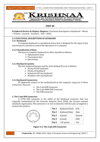
  • 1. Dept of IT | III YEAR | V SEMESTER IT E51 | COMPUTER HARDWARE AND TROUBLESHOOTING | UNIT 3 1 |Prepared By : Mr. PRABU.U/AP |Dept. of Computer Science and Engineering | SKCET | UNIT III Peripheral Devices & Display Adapters: Functional descriptions of keyboard – Mouse – Printers – Joystick – Scanners – CGA – SVGA. 3.1 FUNCTIONAL DESCRIPTIONS OF KEYBOARD 3.1.1 Keyboard A computer keyboard is a peripheral device that is designed for the input of text and characters and also to control the operations of a computer. 3.1.2 Classification of Keys The keys on computer keyboard are often classified as follows:  Alphanumeric keys  Punctuation keys  Special keys 3.1.3 Keyboard Layouts: The four keyboard layouts used for most desktop PCs are as follows:  83-key PC/XT keyboard  84-key AT keyboard  Enhanced 101-key keyboard  Windows 104- key keyboard 3.1.4 Keyboard Connectors: PC keyboards connect to the motherboard on the computer using one of three connectors. They are:  The 5-pin DIN Connector  The 6-pin MINI DIN Connector  The USB Connector 1. The 5-pin DIN Connector: A 5-PIN DIN connector is the oldest of the keyboard connector that was originally standardized by the Deutsche Industrie Norm (DIN), the German national standards organization. The connector is ½ inch in diameter with five pins arranged in a semicircular pattern. Figure 3.1: The 5-pin DIN Connector Pin 1 Keyboard Clock CLK Pin 2 Keyboard Data Data Pin 3 Unused Unused Pin 4 Ground GND Pin 5 +5V power Vcc
  • 2. Dept of IT | III YEAR | V SEMESTER IT E51 | COMPUTER HARDWARE AND TROUBLESHOOTING | UNIT 3 2 |Prepared By : Mr. PRABU.U/AP |Dept. of Computer Science and Engineering | SKCET | 2. The 6-pin MINI-DIN Connector: The 6-pin MINI-DIN Connector also called as PS/2 connector is smaller than the 5-Pin DIN and this is the 5/16 inch in diameter. This mini-Din connector is designed to use six pins arranged in a circular pattern. Here mostly the two unused pins are omitted from keyboard connectors. Figure 3.2: The 6-pin MINI-DIN Connector 3. USB Connector: Universal Serial Bus (USB) is a serial bus standard to interface devices to a host computer. USB was designed to allow many peripherals to be connected using a single standardized interface socket and to improve the Plug and play capabilities by allowing hot swapping, that is, by allowing devices to be connected and disconnected without rebooting the computer or turning off the device. Figure 3.3: The USB trident logo 3.1.5 Keyboards switch Types: 1. Pure mechanical switches: The most basic mechanical switch design is one which depressing the key forces metal contacts together, completing the circuit. 2. Foam element switches: Similar to pure mechanical switches in so far they use an electric circuit between each key and the circuit board below a spring to pop the key back up. 3. Rubber-dome switches: In this design each key is sits on a top rubber dome with an electric contact on its concave underside. The shape of the dome then forces the key back up into its original position. 4. Membrane switches: Similar to rubber-dome switches, except the keytop are all joined into a solid sheet that rest on top of the rubber domes. This provides s a greater amount of protection against the outside environment. Pin 1 Keyboard Data Data Pin 2 Not connected Not connected* Pin 3 Ground GND Pin 4 +5V power Vcc Pin 5 Keyboard Clock CLK Pin 6 Not connected Not connected**
  • 3. Dept of IT | III YEAR | V SEMESTER IT E51 | COMPUTER HARDWARE AND TROUBLESHOOTING | UNIT 3 3 |Prepared By : Mr. PRABU.U/AP |Dept. of Computer Science and Engineering | SKCET | 3.1.6 Keyboard Operation: Figure 3.4: Functional block Diagram of keyboard  When a key is pressed on the keyboard, it sends control signal to the keyboard controller.  The keyboard controller generates a code called scan code corresponding to the signal received.  This code is placed in the keyboard buffer and it sends interrupt signal to the CPU through the system software.  The CPU stops its current execution and reads the scan code from the keyboard buffer.  Then it converts the scan code into its ASCII form. 3.1.7 Types of Keyboards: 1. Dome-switch keyboard Dome-switch keyboards are kind of a hybrid of membrane and mechanical keyboards. They bring two circuit board traces together under a rubber "dome" or bubble. The inside of the top of the bubble is coated in some conductive substance. 2. Capacitive keyboard In this type of keyboard, pressing the key changes the capacitance of a pattern printed on a PC board. Usually this permits a pulse or pulse train to be sensed. Unlike "dome switch" keyboards, the pattern will be covered by a thin, insulating film. 3. Mechanical-switch keyboard Mechanical-switch keyboards use real switches, one under each key. Depending on the construction of the switch, these keyboards have varying responses and travel times. 4. Buckling-spring keyboard  It is a common misconception that the IBM Model M and its derivates are mechanical-switch keyboards.  In fact, the Model M uses membrane-sheet switches, much like those found in a dome-switch keyboard.  The buckling spring mechanism atop the switch is responsible for the tactile and aural response of the keyboard.  This mechanism controls a small hammer that strikes the membrane switch. For more information, see an examination of buckling-spring technology. Keyboard Keyboard controller CPU Keyboard buffer System software
  • 4. Dept of IT | III YEAR | V SEMESTER IT E51 | COMPUTER HARDWARE AND TROUBLESHOOTING | UNIT 3 4 |Prepared By : Mr. PRABU.U/AP |Dept. of Computer Science and Engineering | SKCET | 5. Hall-effect keyboard Hall effect keyboards use magnets and Hall effect sensors instead of an actual switch. When a key is depressed, it moves a magnet, which is detected by the solid-state sensor. These keyboards are extremely reliable, and are able to accept millions of keystrokes before failing. 6. Laser keyboard A laser projection device approximately the size of a computer mouse projects the outline of keyboard keys onto a flat surface, such as a table or desk. When the laser is interrupted in the position of a key, a keystroke is registered. 7. Membrane keyboard Membrane keyboards are usually flat. They are most often found on appliances like microwave ovens or photocopiers. A common design consists of three layers. The top layer (and the one the user touches) has the labels printed on its front and conductive stripes printed on the back. 3.2 MOUSE 3.2.1 Functional Description of Mouse  Mouse is a graphical input device.  This is used to control the cursor movement on the screen by moving it over a flat surface.  It contains two or three buttons on the top.  When the user presses one of the buttons, the mouse either marks a location on the screen or makes selection from data on the screen.  This can also be used in combination with a keyboard. 3.2.2 Classification of Operations on Mouse  The operations on a mouse can be classified into three types. They are  Click  Double click  Drag  To click on an item means to move the mouse pointer to the item on the screen and to press and release the mouse button once.  To double-click on an item means to moue the mouse pointer to the item on the screen and to press and release the mouse button twice in rapid succession.  To drag an item, keep the mouse pointer over the item, then press the mouse button and move the mouse. Release the button after placing the item placing destination position. 3.2.3 Types of Mouse There are three types of mouse interface. They are, i) Serial mouse ii) Bus mouse iii) PS/2 mouse 1. Serial Mouse: A serial mouse is connected to the RS232C Serial Port of the system using a 9-pin or 25-pin female connector.
  • 5. Dept of IT | III YEAR | V SEMESTER IT E51 | COMPUTER HARDWARE AND TROUBLESHOOTING | UNIT 3 5 |Prepared By : Mr. PRABU.U/AP |Dept. of Computer Science and Engineering | SKCET | 2. Bus Mouse: In certain circumstances the serial mouse or the PS/2 mouse cannot be connected to the system (com port). In such case bus mouse is used. It has a stand-alone mouse controller board. It is connected to the system using a 9-pin male DIN connector. 3. PS/2 Mouse:  Now-a-days, computers are fitted with one or two PS/2 ports.  PS/2 mouse uses a 6-pin DIN connector.  In this, the CLK and DATA lines will control the bi-directional data transmission.  The below table shows the signals used in PS/2 mouse. Pin No. Signals 1 Data 2 Reserved 3 Ground 4 +5V 5 Clk 6 Reserved Shield Chassis 3.2.4 Working of a Mouse: The mouse is made up of plastic with one or more switches on the top and ball bearing on its lower surface. Figure 3.5: Working of a Mouse   The ball bearing allows the users to move the mouse in any direction.  On two sides of the ball, at a 90-degree angle. There are two small rollers that touch the ball. This rollers spins when the ball rolls and sense the X and Y direction movements.  A sensor detects how much each roller spins and sends this information to the computer.  The computer translates the information and changes the position of the screen pointer to correspond to the position indicated by the mouse.
  • 6. Dept of IT | III YEAR | V SEMESTER IT E51 | COMPUTER HARDWARE AND TROUBLESHOOTING | UNIT 3 6 |Prepared By : Mr. PRABU.U/AP |Dept. of Computer Science and Engineering | SKCET |  Like the keyboard, a mouse does not actually sense a message directly to the program that the computer is running.  Rather, it sends an interrupt request to the CPU.  The program that is running checks regularly to see whether the mouse has been used.  If it was used, the program acts according to the interrupt given by the system. 3.2.5 Connection: The mouse is connected to the system in two ways. They are, 1. through a 9-pin DIN connector of the Port Com1 or Port Com2. 2. through a PS/2 Socket. Depending on the structure of the cable and the mouse will be either connected to the Port Com1 or the PS/2 connector. 3.2.6 Mouse signals: The table below shows the signals at the connector. Pin No. Signal Direction 1. DCD – Data Carrier Detect From mouse to PC 2. RX – Receive Data From mouse to PC 3. TX – Transmit Data From PC to mouse 4. DTR – Data Terminal Ready From PC to mouse 5. GND – Ground Common Signal 6. DSR – Data Set Ready From mouse to PC 7. RTS – Request To Send From PC to mouse 8. CTS – Clear To Send From mouse to PC 9. RI – Ring Indicator From mouse to PC 3.2.7 Installation of Mouse: To install a mouse follow the steps given below. 1. Switch off the system. 2. Connect the mouse cable end to the Port Com1 or PS/2 as per the option provided. 3. Restart the computer. 4. In the Win 95/98 and above versions it will be auto detected. 5. Otherwise put the device driver disk to install the software.  The device driver software is supplied by manufacture in a floppy disk.  The following command line has to be added in the CONFIG.SYS file. DEVICE = C:MOUSE.SYS  Otherwise the following line is to be included in the AUTOEXEC.BAT C:MOUSE.COM This will make the mouse installation completed. 3.3 PRINTER  The printer is an electromechanical device. It has both electronic circuits and mechanical assemblies.  The electronics circuits control the mechanical assemblies.  Hence the electronic circuits in a printer are usually referred to as printer electronics or control electronics.
  • 7. Dept of IT | III YEAR | V SEMESTER IT E51 | COMPUTER HARDWARE AND TROUBLESHOOTING | UNIT 3 7 |Prepared By : Mr. PRABU.U/AP |Dept. of Computer Science and Engineering | SKCET | Computer Interface Figure 3.6: Printer Block Diagram 3.3.1Printer Functions  The printer receives data characters from the computer and prints the characters on the paper.  In addition, the printer also receives control characters from the computer. The control characters are not printable characters.  They convey some sort of control information to the printer.  Some of the control characters widely used are  CR(Carriage Return)  LF(Line Feed) and  FF(Form Feed) 3.3.2 Printer Characteristics The main characteristics of printer are listed below: 1. SPEED specified as CPS(Characters Per Second), LPM(Lines Per Minute) or PPM (Pages Per Minute). It indicates how fast a printer works. 2. QUALITY specified as DRAFT, NLQ(Near Letter Quality) or LQP(Letter Quality Printer). This implies how good the shape of the printer character is. 3. CHARACTER SET indicating the total number of data characters and control characters recognised by the printer. 4. INTERFACE specifying whether the printer receives characters from the printer in parallel form(one character at a time) or in serial form(one bit at a time). 5. BUFFER SIZE indicating how many data characters can be stacked in the printer buffer memory before printing. 6. PRINT MECHANISM specified as impact dot matrix, impact daisy wheel, impact golf ball, electrosensitive dot matrix, thermal dot matrix, band, belt, drum, train, chain, ink jet or laser. 7. PRINT MODE specified as serial or parallel 8. PRINT SIZE specified as character size and number of characters per line. 9. PRINT DIRECTION specified as unidirectional, reverse, bidirectional logic seeking. 3.3.3 Printer Modules The modules inside a printer are: 1. Print-head mechanism. 2. Carriage-movement mechanism. 3. Paper-feed mechanism. 4. Control electronics. Control and Sense signals Computer Printer Electronics Mechanical Assemblies Paper
  • 8. Dept of IT | III YEAR | V SEMESTER IT E51 | COMPUTER HARDWARE AND TROUBLESHOOTING | UNIT 3 8 |Prepared By : Mr. PRABU.U/AP |Dept. of Computer Science and Engineering | SKCET | 5. Interface logic. 6. Power supply. 3.3.4 Printer Types 1. Impact and Non-Impact Printer In an impact printer, the character is formed by physical(or) pressure of the print head(hammer, pin or font) against an ink and onto paper. The dot matrix printer, daisy wheel printer, golf-ball printer, drum printer, band printer and chain printer are all impact printers.  The Dot matrix impact printer The dot matrix printer does not print a whole character. Each character is formed by small dots. A matrix, usually a 7 by 5, is followed to create the character pattern of dots. The print head consists of pins arranged in a vertical column.  Daisy wheel printer In a daisy wheel printer, the print head consists of a circular wheel. There are 96 spokes or character arms on the wheel. Each spoke has a raised character(print block) marked at the tip. The print quality of a daisy-wheel printer is very good.  Golf-Ball printer In the golf-ball printer, there is a spherical golf-ball like metallic unit. The different characters are marked on the golf-ball, as a raised type around a sphere. To print a character, the drive mechanism causes appropriate movement of the ball, so that character to be printed is brought in front of the desired position on the paper. The print quality of a golf-ball printer is excellent. In a non-impact printer, there is no physical contact of the head with the paper or ribbon. The laser printer, thermal printer, ink jet printer and electrostatic printer are all non-impact printers.  The Laser printer The laser printer operates much like a xerox machine. A laser is used to create an image on a photosensitive drum. For this purpose, the laser is turned on and off, when it sweeps back and forth across the drum. Laser printer offers both letter quality and speed.  Thermal printer Usually, thermal printers use special heat sensitive paper. The print head consists of heating elements. The character are printed as a matrix of dots. When a particular heating element is switched ON, the corresponding spot on the paper is heated and the spot turns dark. Thus spots are burnt onto the paper thereby creating characters or graphics. The thermal printer is quiet and print quality is consistent.  Ink jet printer Ink jet printer provides better quality print out than dot matrix printer. Its output is sharp though not to the same level as a laser printer's output. Still it is very cheap compared to a laser printer.
  • 9. Dept of IT | III YEAR | V SEMESTER IT E51 | COMPUTER HARDWARE AND TROUBLESHOOTING | UNIT 3 9 |Prepared By : Mr. PRABU.U/AP |Dept. of Computer Science and Engineering | SKCET | 2. Character printer and Line printer Character printer In a character printer, characters are printed one after the other. Only one character can be printed at a time. The character printer is also known as serial printer. The daisy wheel printer and dot matrix printer are examples of character printer. Line printer In a line printer, many characters of a line are printed at a time. To an user, the line printer appears to print a complete line of character in one shot. The drum printer, band printer and chain printer are examples of line printers. 3. Draft, LQP and NLQ printers Draft printer In a draft quality printer, the printer character is formed by closely spaced dots, creating character shape. Though the character is visible, it is not impressive because of the presence of dots. The dot matrix printer is an example of a draft printer. LQP(Letter Quality Printer) In a LQP a whole character is formed as a letter(without dots), like a typewriter. It is pleasant to read and hence LQP is widely used in office environments. The daisy wheel printer is an example of a letter quality printer. NLQ(Near Letter Quality Printer) A NLQ printer also prints characters as patterns of dots. But each character is printed twice. The heads(dots) are offset by a minute distance during the second time. 4. Parallel interface and serial interface printer Parallel interface printer In a parallel interface printer, the printer receives all 8 bits of a character simultaneously from the computer. Hence there are 8 data lines between the computer and printer. Serial interface printer In a serial interface printer, the printer receives the 8 bits of character one after the other, in a serial fashion. There is only one data line between the computer and printer. 5. Unidirectional and bidirectional printers Unidirectional printer In an unidirectional printer, the printing is performed only when the print head moves in one direction, i.e., from left to right. This is similar to a manual typewriter operation. Bidirectional printer In a bidirectional printer, printing is performed during both directions of the head movement. If one line is printed when the head moves from left to right, the next line is printed when the print head moves from right to left. The print speed of a bidirectional printer is more than the speed of an unidirectional printer.
  • 10. Dept of IT | III YEAR | V SEMESTER IT E51 | COMPUTER HARDWARE AND TROUBLESHOOTING | UNIT 3 10 |Prepared By : Mr. PRABU.U/AP |Dept. of Computer Science and Engineering | SKCET | 3.4 JOYSTICK  A joystick is a pointing device that moves in all directions and controls the movement of a pointer.  A joystick is similar to a mouse, except that with a mouse the cursor stops moving as soon as you stop moving the mouse.  With a joystick, the pointer continues moving in the direction the joystick is pointing.  To stop the pointer, you must return the joystick to its upright position.  Joysticks are used mostly for computer games  Pressure of stick = velocity of movement  It is also known as the control column  Joysticks are also used for controlling machines such as cranes, trucks, underwater unmanned vehicles, wheelchairs, surveillance cameras, and zero turning radius lawn mowers. 3.4.1 History:  The name "joystick" is thought to originate with early 20th century French pilot Robert Esnault-Pelterie.  Joysticks were commonly used as controllers in first and second generation game consoles, but then gave way to the familiar Game pad with the Nintendo Entertainment System and Sega Master System in 1985 and 86, though joysticks - especially arcade-style ones - were and are popular after-market add-ons for any console.  More recently, analog sticks have become standard on video game consoles and have the ability to indicate the stick's displacement from its neutral position.  This means that the software does not have to keep track of the position or estimate the speed at which the controls are moved. Figure 3.7:Typical diagram of a joystick 3.4.2 Joystick Overview  Joysticks consist of a base and a stick that can be moved in any direction.  The stick can be moved slowly or quickly and in different amounts.  Some joysticks have sticks that can also be rotated to the left or right.  Because of the flexible movements a joystick allows, it can provide much greater control than the keys on a keyboard.  Joysticks typically include several buttons.  Most joysticks have at least one button on the top of the stick and another button in the front of the stick for the trigger.
  • 11. Dept of IT | III YEAR | V SEMESTER IT E51 | COMPUTER HARDWARE AND TROUBLESHOOTING | UNIT 3 11 |Prepared By : Mr. PRABU.U/AP |Dept. of Computer Science and Engineering | SKCET | Figure 3.7: Typical diagram of a Joystick Joystick elements: 1. Stick 2. Base 3. Trigger 4. Extra buttons 5. Autofire switch 6. Throttle 7. Hat Switch 8. Suction Cup 3.4.3 Technical Details  An analog joystick is a joystick which has continuous states, i.e. returns an angle measure of the movement in any direction in the plane or the space (usually utilizing potentiometers) and a digital joystick gives only on/off signals for four different directions, and mechanically possible combinations (such as up-right, down-left) (Digital joysticks were very common as game controllers for the video game consoles, arcade machines, and home computers of the 1980s.)  Additionally joysticks often have one or more fire buttons, used to trigger some kind of action. These are simple on/off switches.  Some joysticks have force feedback capability. These are thus active devices, not just simple input devices.  The computer can return a signal to the joystick that causes it to resist the movement with a returning force or make the joystick vibrate 3.4.4 Types 1.Digital Joysticks  Digital joysticks are the most common joysticks used for PCs, employing simple left, right, up, down and firing commands.  Digital joystick gives only on/off signals for four different directions 2.Paddle Joysticks  Paddle joysticks consist of one knob used to control the game and one firing button.
  • 12. Dept of IT | III YEAR | V SEMESTER IT E51 | COMPUTER HARDWARE AND TROUBLESHOOTING | UNIT 3 12 |Prepared By : Mr. PRABU.U/AP |Dept. of Computer Science and Engineering | SKCET |  This is one of the oldest joysticks, as it was first introduced with the very first home video game consoles. 3.Analog Joysticks  Analog joysticks combine both concepts presented in the digital and paddle joysticks;  they control the game like a digital joystick, but also use to measure the movements like the paddle joysticks.  An analogue joystick is a joystick which has continuous states of the movement in any direction in the plane 4.PC Analog Joysticks  IBM first presented this joystick with their personal computer. It's a simple analog-styled joystick with multiple buttons that usually connects via an USB port. 5.Joypads  Joypads are joysticks without the sticks.  Instead, they employ a directional pad (D-pad) to control the game.  Joypads are considered a bit primitive, but they are still featured among the current video game controllers. 3.4.5 Working of Joysticks  A joystick is a personal computer peripheral or general control device consisting of a handheld stick that pivots about one end and transmits its angle in two or three dimensions to a computer.  Most joysticks are two-dimensional, having two axes of movement (similar to a mouse), but three-dimensional joysticks do exist. A joystick is generally configured so that moving the stick left or right signals movement along the X axis, and moving it forward (up) or back (down) signals movement along the Y axis.  In joysticks that are configured for three-dimensional movement, twisting the stick left (counter-clockwise) or right (clockwise) signals movement along the Z axis. These three axes - X Y and Z - are, in relation to an aircraft, roll, pitch, and yaw.  Joysticks are often used to control video games, and usually have one or more push-buttons whose state can also be read by the computer.  The term joystick has become a synonym for game controllers that can be connected to the computer since the computer defines the input as a "joystick input".  Apart from controlling games, joysticks are also used for controlling machines such as aircraft, cranes, trucks, powered wheelchairs. 3.5 SCANNER  A scanner is an input device that scans documents such as photographs and pages of text.  When a document is scanned, it is converted into a digital format.  Scanners come in black-and-white, or color.  When a document is placed inside a scanner, the image is first scanned and then the scanned data is processed and sent to a computer system.
  • 13. Dept of IT | III YEAR | V SEMESTER IT E51 | COMPUTER HARDWARE AND TROUBLESHOOTING | UNIT 3 13 |Prepared By : Mr. PRABU.U/AP |Dept. of Computer Science and Engineering | SKCET |  Scanners can read red-green-blue color from color array.  Image resolution is measured in pixels per inch. 3.5.1 Types of scanners There are different types of scanners for different types of documents that need to be scanned.  Flatbed Scanners  Sheet-fed Scanners  Handheld Scanners  Drum Scanners  Integrated Scanners  Smartphone Scanners 1.Flatbed Scanner  Used for scanning most documents, photos, and even flat objects from a PC or laptop.  Flatbed scanner works like a copy machine.  Scans documents placed face down on the glass (scan bed)  Most common type of scanner. 2.Sheet-fed Scanner  More portable than a flatbed scanner.  Used to scan paper documents and photos.  The paper moves through the scanner.  Usually smaller than a flat-bed and portable. 3.Handheld Scanner  Smaller than the previous two scanners.  The user must move the scanner across the document.  Image quality us usually lower. 4.Drum Scanner  Used by the publishing industry.  Document is placed on a glass cylinder.  Generates very high quality scans.  These scan an image with photomultiplier tubes (PMT). 5.Integrated Scanners  Modern types of scanners when it comes to obtaining images. ATMs feature this type of built-in scanner for check-processing and approval. 6.Smartphone Scanners  Apps can be downloaded on many smart phone devices, allowing them to scan documents through the digital camera exposures and provide output in JPEG or PDF formats.
  • 14. Dept of IT | III YEAR | V SEMESTER IT E51 | COMPUTER HARDWARE AND TROUBLESHOOTING | UNIT 3 14 |Prepared By : Mr. PRABU.U/AP |Dept. of Computer Science and Engineering | SKCET | 3.5.2 Using Your Scanner  Most flatbed scanners are connected to the computer via the Universal Serial Bus (USB).  A software program called a TWAIN driver is used by the computer to communicate with the scanner.  Most modern Scanners connect to the computer through the USB. 3.5.3 Scanner Software  The TWAIN is a standard of communication between the computer and scanner that all scanner manufacturers agree to that allow images to be directly scanned from an image editing program.  The TWAIN driver controls the scanner and serves as the interface between the scanner and your graphics program. 3.5.4 Scanning a Photo  The image to be scanned should be placed face down on the scanning bed.  The scanner will have a marker indicating where the top of the image should go. 3.5.5 Scanning Formats  Depending on your scanning software, you may have different options of file formats in which to save your scanned image or document.  Images may be saved as:  jpg, bmp, tif, or png.  Documents may be saved as:  pdf, or any of the image formats .bmp  The BMP file format, sometimes called bitmap file format , is an image file format used to store bitmap digital images.  doesn't support color management .tif  Tagged Image File Format (abbreviated TIFF) is a file format for storing images, including photographs and line art.  tif images are considered lossless, meaning when compressed they do not lose any of the data .jpg  jpg is the most common image format used by digital cameras and other photographic image capture devices, and is the most common format for storing and transmitting photographic images on the World Wide Web.  jpg images are considered lossy, meaning when compressed, they lose some of the data .pdf  The Portable Document Format (PDF) is the file format created by Adobe Systems in 1993 for document exchange. 3.5.6 After Scanning  After scanning, you may need to modify your image in a graphic editing program.  Crop  Brightness  Contrast
  • 15. Dept of IT | III YEAR | V SEMESTER IT E51 | COMPUTER HARDWARE AND TROUBLESHOOTING | UNIT 3 15 |Prepared By : Mr. PRABU.U/AP |Dept. of Computer Science and Engineering | SKCET | Crop  To crop an image means to cut away, or trim, the image. Brightness  Refers to the lightness and darkness of a color.  Also referred to as tone or value. Contrast  Contrast is the difference in visual properties that makes an object (or its representation in an image) distinguishable between other objects and the background. 3.6 COLOR GRAPHICS ADAPTER The Color Graphics Adapter (CGA), introduced in 1981, was IBM's first color graphics card (originally sold under the name "Color/Graphics Monitor Adapter"), and the first color computer display standard for the IBM PC. 3.6.1 The CGA color palette '''Full CGA 16-color palette''' 0 — black #000000 8 — (dark) gray #555555 1 — blue #0000AA 9 — bright blue #5555FF 2 — green #00AA00 10 — bright green #55FF55 3 — cyan #00AAAA 11 — bright cyan #55FFFF 4 — red #AA0000 12 — bright red #FF5555 5 — magenta #AA00AA 13 — bright magenta #FF55FF 6 — brown #AA5500 14 — yellow #FFFF55 7 — white (light gray) #AAAAAA 15 — bright white #FFFFFF 3.6.2 Standard text modes CGA offers two text modes: 1. 40×25 characters  It supports up to 16 colors.
  • 16. Dept of IT | III YEAR | V SEMESTER IT E51 | COMPUTER HARDWARE AND TROUBLESHOOTING | UNIT 3 16 |Prepared By : Mr. PRABU.U/AP |Dept. of Computer Science and Engineering | SKCET |  Each character was a pattern of 8×8 dots. The effective screen resolution in this mode was 320×200 pixels (a pixel aspect ratio of 1:1.2), though individual pixels could not be addressed independently.  The choice of patterns for any location was thus limited to one of the 256 available characters, the patterns for which were stored in a ROM chip on the card itself.  The display font in text mode was therefore fixed and could not be changed (although when using the original IBM CGA in an original IBM PC it was possible to select one of two different fonts—normal or thin—by changing a jumper.  The card had sufficient video RAM for 8 different text pages in this mode. 2. 80×25 characters  It supports up to 16 colors.  Each character was again an 8×8 dot pattern (the same character set was used as for 40×25), in a pixel aspect ratio of 1:2.4.  The effective screen resolution of this mode was 640×200 pixels.  Again, the pixels could not be individually addressed.  Since there were twice as many characters on the screen in this mode, the card had enough video RAM just for 4 different text pages. 3.6.3 Standard RGB graphics modes CGA offered two commonly-used graphics modes:  320×200 pixels, as with the 40×25 text mode. In the graphics mode, however, each pixel could be addressed independently. The trade-off was that only 4 colors could be displayed at a time. These four colors could not be freely chosen from the 16 CGA colors — there were only two official palettes for this mode: 1. Magenta, cyan, white and background color (black by default). 2. Red, green, brown/yellow and background color (black by default).  640×200 pixels, as with the 80×25 text mode. All pixels could be addressed independently. This mode was monochrome, offering only black and white as colors (though this could be changed), with a pixel aspect ratio of 1:2.4. Fixed CGA 4-color palette #1 default 5 — magenta 3 — cyan 7 — white (light gray) Fixed CGA 4-color palette #2 default 4 — red 2 — green 6 — brown (orange)
  • 17. Dept of IT | III YEAR | V SEMESTER IT E51 | COMPUTER HARDWARE AND TROUBLESHOOTING | UNIT 3 17 |Prepared By : Mr. PRABU.U/AP |Dept. of Computer Science and Engineering | SKCET | 3.6.4 Specifications Connector: Figure 3.8: DE-9 Connector Pin assignments Pin Function 1 Ground 2 Ground 3 Red 4 Green 5 Blue 6 Intensity 7 Reserved 8 Horizontal Sync 9 Vertical Sync Figure 3.9: Pin Assignments Signal: Type Digital, TTL Resolution 640h × 200v, 320h × 200v H-freq 15.75 kHz V-freq 60 Hz Colors 16 Figure 3.10: Signal 3.6.5 Competing adapters CGA had two main competitors: 1. Monochrome Display Adapter (MDA)  For business and word processing use, IBM launched its Monochrome Display Adapter (MDA) at the same time as CGA.  The MDA produced a higher resolution text display in 80×25 mode, rendering each character in a box of 9×14 pixels, of which 7×11 were the character itself.  This produced sharper characters than the CGA's 8×8 dots text character matrix allowed.  Because of this and CGA's higher price at the time, MDA was often preferred for business use.
  • 18. Dept of IT | III YEAR | V SEMESTER IT E51 | COMPUTER HARDWARE AND TROUBLESHOOTING | UNIT 3 18 |Prepared By : Mr. PRABU.U/AP |Dept. of Computer Science and Engineering | SKCET | 2. Hercules Graphics Card (HGC)  In 1982, the non-IBM Hercules Graphics Card (HGC) was introduced.  In addition to an MDA-compatible text mode, it offered a monochrome graphics mode. With a resolution of 720×348 pixels, the graphics mode was better than what CGA could produce.  The Hercules adapter's offer of better monochrome graphics and its ability to work with less expensive monochrome monitors made it a desirable choice for many. 3.7 SUPER VIDEO GRAPHICS ARRAY Super Video Graphics Array, almost always abbreviated to Super VGA or just SVGA is a broad term that covers a wide range of computer display standards. Figure 3.11: 15-pin D-sub port 3.7.1 SVGA Overview  Originally, it was an extension to the VGA standard first released by IBM in 1987. Unlike VGA—a purely IBM-defined standard—Super VGA was defined by the Video Electronics Standards Association (VESA), an open consortium set up to promote interoperability and define standards.  When used as a resolution specification, in contrast to VGA or XGA for example, the term SVGA normally refers to a resolution of 800 × 600 pixels. 3.7.2 SVGA Extension  Super VGA was first defined in 1989. In that first version, it called for a resolution of 800 × 600 4-bit pixels.  Each pixel could therefore be any of 16 different colors.  It was quickly extended to 1024 × 768 8-bit pixels, and well beyond that in the following years. 3.7.3 SVGA Monitor  Although the number of colors was defined in the original specification, this soon became irrelevant as (in contrast to the old CGA and EGA standards) the interface between the video card and the VGA or Super VGA monitor uses simple analog voltages to indicate the desired colour depth. In consequence, so far as the monitor is concerned, there is no theoretical limit to the number of different colors that can be displayed.  Note that this applies to any VGA or Super VGA monitor.
  • 19. Dept of IT | III YEAR | V SEMESTER IT E51 | COMPUTER HARDWARE AND TROUBLESHOOTING | UNIT 3 19 |Prepared By : Mr. PRABU.U/AP |Dept. of Computer Science and Engineering | SKCET | 3.7.4 SVGA Card  While the output of a VGA or Super VGA video card is analog, the internal calculations the card performs in order to arrive at these output voltages are entirely digital.  To increase the number of colors a Super VGA display system can reproduce, no change at all is needed for the monitor, but the video card needs to handle much larger numbers and may well need to be redesigned from scratch.  Even so, the leading graphics chip vendors were producing parts for high-colour video cards within just a few months of Super VGA's introduction. 3.7.5 SXGA On paper, the original Super VGA was to be succeeded by Super XGA, but in practice the industry soon abandoned the attempt to provide a unique name for each higher display standard, and almost all display systems made between the late 1990s and the early 2000s are classed as Super VGA. 3.7.6 Performance Monitor manufacturers sometimes advertise their products as XGA or Super XGA. In practice this means little, since all Super VGA monitors manufactured since the later 1990s have been capable of at least XGA and usually considerably higher performance.