Siemens Medium-Voltage Gas-Insulated Switchgear Technical Overview
•Download as PPTX, PDF•
0 likes•769 views

- Siemens medium-voltage gas-insulated arc-resistant switchgear provides increased safety, improved reliability, and increased flexibility with innovative features in a compact design that is easy to use and cost effective. - It uses SF6 gas insulation for all primary components, which provides advantages over air insulation including a compact footprint, higher dielectric strength, and maintenance-free operation in a controlled gas environment. - Key benefits include enhanced personnel safety due to its arc-resistant design, high operational availability and reliability due to its sealed pressure system, and minimized maintenance requirements over its lifetime.

Recommended
More Related Content
What's hot
What's hot (20)
Similar to Siemens Medium-Voltage Gas-Insulated Switchgear Technical Overview
Similar to Siemens Medium-Voltage Gas-Insulated Switchgear Technical Overview (20)
More from Power System Operation
More from Power System Operation (20)
Recently uploaded
Recently uploaded (20)
Siemens Medium-Voltage Gas-Insulated Switchgear Technical Overview
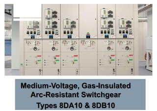
- 1. Medium-Voltage, Gas-Insulated Arc-Resistant Switchgear Types 8DA10 & 8DB10
- 2. Siemens medium-voltage gas-insulated arc-resistant switchgearis: Increased safety1 Improved reliability2 3 Increased flexibility 4 Innovative features 5 Easy to use Cost effective6 Type 8DA10 gas-insulated arc-resistantswitchgear Power Distribution Medium-Voltage Gas-Insulated Switchgear Page 2
- 3. • Non toxic • No hazardous substance 1) • Colorless, odorless and chemical neutral(inert) • Heavier then air • ... with compact design • ... with high personnel safety • ... with minimized fire load • ... with high operational availability & reliability Until today no climate-neutral gas is known with comparablecharacteristics Core Technology: Insulating Medium SF6 SF6 technology enableselectrical equipment ... Page 3
- 4. • Vacuum interrupter technology • Ratings: • Maximum voltage: 4.76 kV, 15 kV, 27 kV or 38 kV • Continuous section current: up to 2,500 A (or 4,000 A using parallel circuitbreakers) • Short-circuit current: up to 40 kA • Lightning-impulse withstand (BIL): up to 200 kV • Tested to ANSI/IEEE C37.20.7-2007/ IEC 62271-200 arc-resistant internal arc classification type 2B (front, side, rear with low- voltage compartment door open) • Low-pressure SF6 gas used as an insulating medium for all primary components • Primary components virtually maintenance-free due to controlled gas environment Page 4 Medium-Voltage Gas-Insulated Switchgear Features & Benefits
- 5. © Siemens Industry, Inc. 2016. • Circuit breaker endurance: • Mechanical endurance: 10,000 times • Mechanical endurance (optional): 30,000 times • Electrical endurance : 10,000 times • Full-fault switching capability: 50 times • Compact footprint per section: • 24” W x 64” D (8DA10 single bus) • 24” W x 105” D (8DB10 double bus) • Integral isolation by use of a three-position selector switch (CONNECTED, DISCONNECT & GROUND positions) • Fixed-mounted circuit breakers (no special tools for racking or lift truck for handling) • Over 94,000 sections installed worldwide with more than 4,500 installed in the U.S Medium-Voltage Gas-Insulated Switchgear Features & Benefits Page 5
- 6. Medium-Voltage Gas-Insulated Switchgear 8DA10 Single Busbar Lineup Up To 42 kV Page 6 Front view Available at Koontz Wagner, 6510- Bourgeois Houston, TX 77066
- 7. 8DA10 single bus bar 8DB10 double bus bar Medium-Voltage Gas-Insulated Switchgear Types 8DA10 & 8DB10 Isolated-phase design eliminates possibility of phase-to-phase faults inside the switchgear Page 7
- 8. Medium-Voltage Gas-Insulated Switchgear Compartmentalization Single-busbar switchgear Arrangement of gas-filled compartments 1 2 3 Item Description 1, 2, 3 Gas zone, one each for main bus phase 1, phase 2 & phase 3 4 Gas zone, common for circuit breaker phase 1, 2 & 3 associated feeder connections 5 Gas zone, common for bus sectionalizer bus for phases 1, 2 & 3 1 2 3 5 4 Page 8 1 2 3
- 9. © Siemens Industry, Inc. 2016. Item Unit Single-busbar (8DA10) & double-busbar (8DB10) switchgear Single- pole (8DA11) & double- pole (8DA12) traction power supply switchgear* Rated maximum design voltage kV 15 27 38** 17.5 27.5 Rated frequency Hz 50/60 50/60 50/60 16.7 50/60 Rated short-duration power-frequency withstand voltage kV 36 50 80 50 95 Rated lightning-impulse withstand voltage kV 95 125 200 125 200 Rated peak-withstand current kA 104 104 104 82 104 Rated short-circuit making current (peak) kA 104 104 104 82 104 Rated short-circuit withstand current 3 s kA 40 40 40 31.5 40 Rated short-circuit breaker current kA 40 40 40 31.5 40 Rated normal current of busbar, maximum A 5,000 5,000 5,000 2,500 3,150 Rated normal current of feeders, maximum A 2,500 2,500 2,500 2,000 2,500 Medium-Voltage Gas-Insulated Switchgear Technical Data * Consult Siemens Smart Grid division, Rail Electrification business, for information on traction power supply switchgear. http://w3.usa.siemens.com/smartgrid/us/en/rail-electrification/Pages/Rail-Electrification.aspx ** Consult Siemens for rated maximum design voltage up to 42 kV. Page 9
- 10. Footprint comparison (MV AIS & MV GIS - only equipment size considered) 38 kV 15 kV MV AIS MV GIS MV GIS MV AIS ~75% ~55% Space saving Medium-Voltage Gas-Insulated Switchgear MV GIS Smaller Than MV AIS – Compact Footprint Single bus Page 10 comparison
- 11. • Tested to ANSI/IEEE C37.20.7-2007/IEC 62271-200 for internal arcing faults • Arc-resistant internal arc classification type 2B (front, side, rear with low-voltage compartment door open) • Reduced level of PPE permitted by NFPA 70E for arc-resistant switchgear Page 11 Medium-Voltage Gas-Insulated Switchgear MV GIS Is Tested For Arc Resistance
- 12. Comparison of PPE3 level required foroperations Activity MV air-insulated switchgear (AIS)1 MV GIS Open/close circuit breaker HRC 2 (door closed)2 HRC 4 (door open) HRC 04 Isolate circuit HRC 4 (racking, door open or closed) (Note: isolation in metal-clad requires racking to test or disconnect position) HRC 0 (operation of three-position switch to open position) Application of safety grounds HRC 4 HRC 04 Page 12 1 Non-arc-resistant. 2 HRC = hazard risk category HRC 0 = lowest level HRC 2 = 8 cal/cm2 PPE HRC 4 = 40 cal/cm2 PPE. 3 Derived from tables 130.7 (c) (15) (a) in NFPA 70E-2012. Refer to NEC 70E for detailed requirements. 4 HRC 0: non-melting or untreated natural fiber-protective clothing, long-sleeved shirt, long pants, safety glasses or goggles, hearing protection. For Major Operational Activities Reduced Level Of PPE Can Be Used For MV GIS
- 13. UL/cUL Listed* as arc resistant to ANSI/IEEE C37.20.7-2007 * Ratings dependent Medium-Voltage Gas-Insulated Switchgear UL Listed* Page 13
- 14. Low-voltage compartment Page 14 Busbar Drive mechanism/ three-position switch Gas monitoring Drive mechanism/ circuit breaker Circuit breaker pole housing Current transformer Cable connection from the bottom Medium-Voltage Gas-Insulated Switchgear Circuit Breaker Section (8DA10 Single Bus Shown)
- 15. Busbar housing Three-position switch (shown OPEN) Pole housing Medium-Voltage Gas-Insulated Switchgear Busbar Design Up To 5000 A Busbar 5000A Busbar up to 4000A Busbar Busbar Twin busbar housing Busbar Page 15
- 16. Medium-Voltage Gas-Insulated Switchgear Three-Position Selector Switch OPEN Page 16 READY-TO- GROUND CLOSED
- 17. • Compact – same footprint from 2.4 kV to 42 kV • Gas insulation eliminates derating due to altitude • Video camera system to view three- position switch status – complies with NEC visible disconnect requirement (NEC 225.51 & 230.204) • Capacitive voltage indicators – avoids need for hot-stick for checking energization of primary • Integral grounding switch – grounding cables are unnecessary Overview of innovative features Medium-Voltage Gas-Insulated Switchgear Innovative Features Page 17
- 18. 8DA/B ANSI Camera housing and mounting Page 18
- 19. 8DA/B ANSI Hardware RJ45 (ethernet) and USB connector on laptop necessary USB-A 2.0 or 3.0 Ethernet Ethernet connection USB interface Screw caps for protection 1 3 2 © Siemens Industry, Inc. 2016. Page 19 2014 IC1000-F320-A121-X-4A00 Murtaza Khan MS U.S.
- 20. 8DA/B ANSI Software No special software tool and software expertise required Only web browser is needed Mozilla Firefox Microsoft Internet Explorer Google Chrome Safari Other browsers might work, but are not covered with development tests Ethernet connection USB interface Screw caps for protection 12 3 Page 20
- 21. 8DA/B ANSI Operation Open screw caps (at switchgear front or rear wherever it is applicable) Connect USB and RJ45 plugs (between switchgear interface and laptop, cables are supplied) Start web browser and type in any address Three reference pictures on top view (CLOSED, OPEN, GROUNDED) Camera live-view below Three software buttons available to switch view from phase L1, L2 and L3 Ethernet connection USB interface Screw caps for protection 1 3 2 Page 21
- 22. Medium-Voltage Gas-Insulated Switchgear View Port Via Video Camera Page 22 Use of PC to view position of selector switch
- 23. C2 C1 Potential indicator or indicator Medium-Voltage Gas-Insulated Switchgear Capacitively Coupled Voltage Indication System Page 23 • Coupling electrode built into pole-support plate of the circuit breaker • For checking the energization state ofeach pole • No hot stick required to check voltage presence Plug-in LRM voltage indicator
- 24. Circuit OFF & ISOLATED Ready To Ground Circuit GROUNDED Circuit CLOSED Medium-Voltage Gas-Insulated Switchgear Three-Position Selector Switch Page 24
- 26. • Sealed pressure system protects against environmental influences (IP65) • Single-pole enclosure eliminates possibility of phase-to-phase faults inside switchgear • Division of gas compartments enables rapid problem isolation • Mean time between major failure: • MV GIS — 5,300 years (based on last 10 years data) • MV AIS — 856 years (estimate) Sources: IEEE 493 Gold Book (for MV AIS), Siemens internal data (for MV GIS) Overview of reliability features Medium-Voltage Gas-Insulated Switchgear High-Operational Reliability Page 26
- 27. Source: IEEE 493 Gold Book, Annex E, table XVIII, page 479 • Thermocycling • Mechanical structure failure • Mechanical damage from foreign source • Shorting by snakes, birds, rodents, etc. • Malfunction of protective device • Above normal ambient • Exposure to chemicals or solvents • Exposure to moisture • Exposure to dust or other contaminants • Exposure to non-electrical fire • Normal deterioration from age • Severe weather condition • Others 7% 3% 7% 3% 10% 3% 3% 30% 10% 7% 10% 3% 4% Share Not applicable to MV GIS Estimated 50% of failure causes not applicable with MV GIS Page 27 OverviewoffailurecausesforMVAIS Medium-Voltage Gas-Insulated Switchgear Reduces Or Eliminates Causes Of 50% Of Failures In MV AIS MV AIS failure cause
- 28. • Vacuum interrupter mounted in circuit breaker pole housing • Non-sliding current transfer from vacuum interrupter moving contact to three-position switch Page 28 Medium-Voltage Gas-Insulated Switchgear Vacuum Interrupter
- 29. Ring-core current transformers: • Current transformers located outside gas zone • Secondary part accessible outside the enclosure (& gas zone) without exposure to primary voltage • Free of dielectrically- stressed cast-resin parts A C B A Page 29 Medium-Voltage Gas-Insulated Switchgear Current Measurement Current transformer installation (basic scheme) Item Description A Feeder current transformer on the cable housing B Feeder current transformer on the cable C Busbar current transformer
- 30. • Mounted separately & connected via a plug-in cable • Grounded metal-enclosed • Connected line-ground • VT solid insulated with grounded metal-enclosure • Outside main circuit • Fused • No gas work required to remove or install Voltage transformer with primary fuse Medium-Voltage Gas-Insulated Switchgear Line-Side (Cable-Side) Voltage Transformer Item Description 1 Bus connected VT 2 Cable connected VT 1 2 Page 30
- 31. • Internal cone type plug-in connections per EN-50181/DIN 47637 • Sizes available up to 1,250 A per conductor (cable) and up to 2,500A for cast-epoxy insulated bus • Size 2, up to 40 mm (1.57”) O.D., up to 800A • Size 3, up to 46 mm (1.81”) O.D., up to 1,250A • Size 3.5, up to 50 mm (1.97”) O.D., up to 1,250A • Diameter is over insulation, without voltage detection tap Page 31 Medium-Voltage Gas-Insulated Switchgear Plug-In Cable Termination System
- 32. Medium-Voltage Gas-Insulated Switchgear Low Maintenance Over Life Cycle Page 32 Types 8DA10/8DB10 Visual inspection Every 5 years Condition inspection Every 10 years Maintenance After 1,000 operating cycles of the disconnectors & grounding switches or after 10,000 operating cycles ofthe circuit breaker. These intervals are guidelines which have to be adjusted to the different operating conditions (i.e., dusty environment, frequent condensation, etc.) which can affect operating mechanism
- 33. Medium-Voltage Gas-Insulated Switchgear Maintenance Checks Page 33 Visual inspection Condition inspection Maintenance Description X X X Check & document SF6 gaspressure X X Check & document dew-point (humidity content) (≤15 ˚C) X X Check & document gas quality (air content) (SF6 share ≥95%) X Check operating mechanism & interlocking of disconnector & grounding switch. If required, grease linkage & bearings. X Vacuum circuit breaker operating mechanism
- 34. Dielectric withstand in relation to gas pressure/leakage (example: 38 kV) Gas pressure(abs.) 0/100 50/50 100/0 1.0 1.3 1.5 1.7 bar 200 50 SF6 / air mixture (%) SF6 at gauge pressure 0 100 ANSI rated 60 Hz withstand 80 ANSI rated impulse (BIL) 150 30 Switching under normal conditions still possible Medium-Voltage Gas-Insulated Switchgear Dielectric Withstand Normal atmospheric pressure Page 34
- 35. Page35 ReliabilityFootprint Maintenance MV AIS Consider not just the one-time purchase cost, but also the total life-cycle cost Spare Parts MV GIS Safety Medium-Voltage Gas-Insulated Switchgear Consider These Investment Decision Advantages
- 36. Questions Answers Can the circuit breaker interrupt if there is a leak and no SF6 gas is available? Yes, the vacuum interrupters are independent of the SF6 gas and all the interruption occurs inside the vacuum interrupters. SF6 gas is only used for insulation. What is the SF6 leakage rate in Siemens MV GIS 8DA/B? The low leakage rate is possible as the normal pressure is 1.5 bar (22 psig) or less, and the SF6 gas is used only for insulation, not for interruption. Leakage is below 0.1% per year. Page 36 Go-To-Market FAQs
- 37. Questions Answers Is SF6 a greenhouse gas“GHG”? Yes, SF6 is a GHG with atmospheric lifetime of 3,200 years. Are there any taxes applicable on use of SF6 gas in MV switchgear or any regulatory requirements? No, users are required to report annually SF6 volume if their inventory exceeds 17,800 lbs at any time. How do I quantify 17,800 lbs of SF6 gas in terms of number of sections? 8DA10 ~ 2,700 sections 8DB10 ~ 1,400 sections What is the percentage ofemissions of SF6 gas from T&D equipments compare to the total emissions of all the gases in the U.S.? In 2013, total emissions of all GHG reported was 5,791.2 MMT CO2 equivalent. Emissions from T&D equipments were 5.1 MMT CO2 equivalent. Net emission from T&D equipment was < 0.1% (5.1/5,791.2) Page 37 Go-To-Market FAQs
- 38. Reference project in Utility/IOU Page 38 Customer information Customer: Georgia Power (Demo Unit) Location: Georgia Project information Equipment type: 8DB Number of sections: 4 Voltage: 25 kV Short-circuit current: 40 kA Year of installation: 2009
- 39. Reference project in Pharmaceutical Page 39 Customer information Customer: Amgen, Inc. Location: Washington Project information Equipment type: 8DA Number of sections: 50 Voltage: 4.16 kV and 26.4 kV Short-circuit current: 40 kA Year of installation: 2001
- 40. Reference project in Heavy Industry/Manufacturing Page 40 Customer information Customer: Caterpillar, Inc. Location: Illinois Project information Equipment type: 8DA Number of sections: 40 Voltage: 13.8 kV Short-circuit current: 40 kA Year of installation: 2008 (shown during installation)
- 41. Reference project in Oil and Gas/Refinery Page 41 Customer information Customer: ConocoPhillips Location: Wood River, Illinois Project information Equipment type: 8DA Number of sections: 54 Voltage: 38 kV Short-circuit current: 40 kA Year of installation: 2009
- 42. Reference project in Oil and Gas/Refinery Page 42 Customer information Customer: Hovensa Refinery Location: St. Croix, U.S. Virgin Islands Project information Equipment type: 8DA Number of sections: 54 Voltage: 38 kV Short-circuit current: 40 kA Year of installation: 2005
- 43. Reference project in Oil and Gas/Extraction Customer information Customer: Canadian Natural Resources Ltd. - Horizon Oil Sands Location: Alberta, Canada Project information Equipment type: 8DA Number of sections: 265 Voltage: 5 kV, 15 kV and 38 kV Short-circuit current: 40 kA Year of installation: 2005 Page 43
- 44. Reference project in Higher Education Page 44 Customer information Customer: NOVA Southeastern University Location: Florida Project information Equipment type: 8DA Number of sections: 265 Voltage: 4.16 kV and 13.8 kV Short-circuit current: 40 kA Year of installation: 2009
- 45. Manufacturing Location Siemens MV GIS Manufacturing in Frankfurt (SWF): The Home ofGIS! Page 45
- 46. Medium-Voltage Gas-Insulated Switchgear Page 46 GIS compared to AIS
- 47. Fixed-type, gas-insulated medium-voltage switchgear compared to air-insulated switchgear T comparison 2016
- 48. MV AIS Page 48 • Drawout type construction, where circuit isolation is achieved by opening the circuit breaker and then racking it to the test or disconnect position. • No built-in circuit grounding capability. Grounding of load circuit requires drawout ground and test device. MV GIS • Fixed-mounted circuit breakers with interlocked isolation switch and grounding switch. Isolation meets NEC visible disconnect requirement. • Grounding accomplished with grounding switch and circuit breaker with fault-making capability. Sequential interlocking prohibits mis-operation. MV GIS Comparison To MV AIS
- 49. MV AIS Page 49 • Drawout type construction, requiring physical movement of circuit breaker from connected to test or disconnect position. • Historic experience suggests higher potential for failures associated during racking. MV GIS • GIS achieves isolation without the movement of the circuit breaker, eliminating the potential for misalignment. MV GIS Comparison To MV AIS
- 50. MV GIS Comparison To MV AIS Page 50 MV AIS • Conventional-type cable termination (cable lugs and stress cones), exposed to contaminants MV GIS • Plug-in type cable termination, which provides IP65 protection and easy installation at site
- 51. Siemens MV GIS Advantages Page 51 MV GIS offers the advantages of a switching device - a minimum number of parts resulting in a high MTBF 1. No regular maintenance 1.Visual inspection: 5 years 2.Status inspection: 10 years 3. Maintenance after 10,000 operations 2. No impact from environmental conditions (except for flooding) 3. Highest IP protection by having IP65 for high-voltage parts. 4. Highest personal safety. 5. Operational safety 6. Compact design 7. No extra-storage space required 1. Saves costs - no shutdowns needed. 2. Saves insulators from dust; provides constant insulation quality. 3. No penetration of foreign bodies like dust, small animals and moisture. 4. High-voltage part installed in gas-insulated, sealed housing so no access to high-voltage parts. Fool-proof interlocks. 5. Low-maintenance switching device. Cable grounding via the circuit breaker. Risk of internal arcs minimized. 6. Up to ~75% space saving vs AIS. 7. Only a few small secondary spare parts recommended.
- 52. Footprint comparison (MV AIS & MV GIS - only equipment size considered) 38 kV 15 kV MV AIS MV GIS MV GIS MV AIS ~75% ~55% MV GIS Smaller Than MV AIS – Compact Footprint Single bus Space saving Page 52 comparison
- 53. MV GIS Advantages - Maintenance MV AIS Required latest after 5 years of service: • Switch off of lines, feeders and busbars • Grounding • All circuit breakers in testposition • Test function of circuit breakers andand all other switching devices • Remove the drawout circuit breaker andremove covers partly to access to busbars and cable sections • Clean the sections and all insulation, and check all bolted connections • Lubricate all bearings and surfaces; check panel function and put switchgear back intoservice Example: Estimated time per section: 4 hours For a 20-section lineup 80 working hours, respective to 8 working days for maintenance Average $180 per person per hour, i.e., $14,400 for a 20-section lineup MV GIS • Requires minimal maintenance • Visual inspection: 5 years • Check gas-pressure gauges • General visual survey. Example: For the 20-section lineup, potential savings $14,400. After 30 years, total savings $86,400 Page 53
- 54. MV GIS Advantages - Availability MV AIS • During maintenance, switchgear is out of service. • Provisions for alternative supply circuits must exist. • Switching procedures must be followed. • After maintenance, original conditions need to be re-established. Risks: • Switching failures. • Network disturbances may occur. • Human errors, tools left in equipment, loose connections, loose bolts, missing covers, etc. Therefore, the risk of failures inside the switchgear (including potential for arc fault) may be higher. MV GIS • Almost maintenance free. • No human errors can occur due to hermetically- sealed isolation. • Insulation cannot be contaminated. Peace of mind Page 54
- 55. MV GIS Advantages – Environmental Aspects MV AIS • Influence of dust, humidity and vermin to active parts as busbars, breakers, cableconnections: • Need of maintenance, cleaning ofinsulation • Condensation – potential for partial discharges and damage to insulation. • Need to eliminate potential for verminin switchgear • Reduction in dielectric withstand (hipot and impulse) for high altitudes Example: 27 kV AIS at altitude of 6,562 ft (2,000 m) needs rated insulation level of 138 kV BIL to provide 125 kV BIL at 6,562 ft (2,000 m). Since this cannot be reached with 27 kV AIS, 38 kV AIS is required, which means higher costs. Additional costs and control are necessary. MV GIS • No environmental influences (flooding exception) due to maintenance-free, hermetically sealed (HV) switchgear. • No influence of insulation level due to altitude. Example: Peace of mind and cost savings. Page 55
- 56. MV GIS Advantages - Dimensions MV AIS For 27 kV, 2,000 A, 25 kA, AIS dimensions: • Width: 3.0 ft (.91 m) • Depth: 8.0 ft (2.4 m) Floor space per section is equal to 24.0 ft² (2.2 m2) Example: 20-section lineup, area required: • 480.0 ft² without required rear aisle • 840.0 ft² with NEC clear working space in rear. MV GIS For 27 kV, 2,000 A, 25 kA GIS dimensions: • Width: 1.97 ft (.6 m) • Depth: 5.3 ft (1.62 m) Floor space per section is equal to 10.4 ft² (1.0 m2) and no working space required at rear Example: 20-section lineup, area required: • 209.0 ft² and no rear aisle required. Page 56 Savings Value 271 ft2 without rear aisle $13.6 k to $180.3 k 631 ft2 with rear aisle $31.6 k to $419.8 k Source for $ per ft² :http://www.businessinsider.com/us-city-
- 57. Aisle space “I have to double the substation MVA, but don’t have the space?” 38 kV switchgear space requirements single bus comparison Air-insulated switchgear 99.3 ft2 = 9.2 m2 Gas-insulated switchgear 22.7 ft2 = 2.1 m2 48” (1,219) 130” (3,302mm) Page 57 72” (1,827 mm) aisle space (NEC) 64” (1,626mm) 24” (610mm) 72” (1,827 mm) minimum rear access(NEC) 96” (2,438mm) drawout space Space Problems? MV GIS Advantages * * No rear access required, eliminating need for rear aisle
- 58. MV GIS Advantages - Reliability Source: IEEE 493 Gold Book, Annex E, table XVIII, page 479 • Thermocycling • Mechanical structure failure • Mechanical damage from foreign source • Shorting by snakes, birds, rodents, etc. • Malfunction of protective device • Above normal ambient • Exposure to chemicals or solvents • Exposure to moisture • Exposure to dust or other contaminants • Exposure to non-electrical fire • Normal deterioration from age • Severe weather condition • Others 7% 3% 7% 3% 10% 3% 3% 30% 10% 7% 10% 3% 4% Share Not applicable to MV GIS Estimated 50% of failure causes not applicable with MV GIS Page 58 MV AIS failure cause OverviewoffailurecausesforMVAIS
- 59. MV GIS Advantages – 150 kV BIL MV AIS Due to the requirement of 150 kV BIL at 27 kV, the switchgear selection should be upgraded to the next voltage level. This BIL value cannot be reached with typical 27 kV switchgear. Therefore, 38kV switchgear is required, which means higher costs for the customer: • Higher equipment costs • Much higher costs for real estate. MV GIS • Same design & footprint for voltages up to 40.5 kV • No environmental influences due to maintenance -free, hermetically-sealed (HV portion) switchgear. Cost savings. Page 59
- 60. MV GIS Advantages – Spare Parts MV AIS For an estimated lifetime of 30 years, spares needed. •Lubricants •Screws •Bolts •Nuts •Contact fingers for draw out unit •Isolators •Bushings Therefore additional cost for spares, storage , handling, installation of parts, staff for exchange the parts incurred. MV GIS Few small secondary parts recommended. Cost savings due to minimal cost of spares, no additional storage room, handling cost and cost of staff. Page 60
- 61. Thank You