RLW type pole mounted vacuum load break switch
•
1 like•502 views

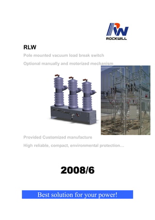
Pole mounted vacuum load break switch, from 11kV up to 38kV.

Recommended
More Related Content
What's hot
What's hot (20)
Similar to RLW type pole mounted vacuum load break switch
Similar to RLW type pole mounted vacuum load break switch (20)
Recently uploaded
Recently uploaded (20)
RLW type pole mounted vacuum load break switch
- 1. RLW Pole mounted vacuum load break switch Optional manually and motorized mechanism Provided Customized manufacture High reliable, compact, environmental protection… 2008/6 Best solution for your power!
- 2. 1. Summary 1.1General RLW type medium-voltage pole mounted vacuum load break switch is a 3 phase full new design technology switch. Its used on overhead distribution lines as well as distribution substation applications for voltage classes 11kV up to 38kV. and its rated current can reach up to 1250A. System solution for switching and sectionalizing line as well as automation and control systems, e.g. in: ■ Power plants ■ Switching substations ■ Companies in all industrial sectors ■ Water treatment plants ■ Office and administrative buildings ■ Airports and logistic centres ■ Oil/Gas plants 1.2 Standards and specifications 1.2.1 Switchgear manufacture The switchgear complies with the following specifications in accordance with relevant IEC publications: • IEC62271-100/ GB1984-2003 or ANSI/IEEE C37.66 1.3 Operating conditions 1.3.1 Normal operating conditions Design to relevant standard, with the following limit values: • Ambient temperature: –Maximum +40℃, –Maximum 24 hour average +35℃ –Minimum (according to “minus 5 indoor class”) –40℃ • Humidity: –Monthly average humidity 95%; Daily average humidity 90% . • Maximum site altitude: ≤ 3000 M above sea level. 1.3.2 Special operating conditions Special operating conditions are to be agreed on by the manufacturer and user. The manufacturer must be consulted in advance about each special operating condition: • Site altitude over 1000 m: –Allow for the reduction in the dielectric strength of the air. • Increased ambient temperature: –Current carrying capacity is reduced. –Provide additional ventilation for heat dissipation. • Climate: –Avoid the risk of corrosion or other damage in areas: • with high humidity and/or with major rapid temperature fluctuations. – Implement preventive measures (e.g. electric heaters) to preclude condensation phenomena. –
- 3. 2. Main new advantages of RLW 2.1 The VLBS tank feature: The Vacuum load break switch tanks are manufactured from 304#grade stainless steel and standard tank are powder coated a light grey colour. Whole load break switch IP65 protection class, equipped with a auxiliary plug to connect with load break switch controller by control cable, Diameter Max22mm, up to 6 M length(8M for special). It can performance serve more than 20 years long term under heavy duty circumstance. 2.2 The vacuum embedded pole feature: The load break switch’s vacuum interrupter insert in an epoxy resin solid pole, and external coated with a high reliable, stable material: Fluorocarbon silicone rubber (γ-trifluoro propyl methyl polysiloxane) With excellent electric insulation, weather resistance, ozone, biological inertia, can be stand under the long-term use in -55 ~ +200 ℃. 2.3 Creepage Distances of RLW Description 15kV BIL 95kV 15kV BIL 110kV 27kV BIL 125/150kV 38kV BIL 150/170kV T to T* 480mm More than 968mm T to G/E* 480mm More than 960mm T to T* -----Terminal to terminal creepage T to G/E* -----Terminal to ground/earth creepage 3. Optional for difference functions of primacy design 3.1 Optional for Difference configurations of primacy design (Interruptering pole) Basic VI pole,BIL170kV VI pole with CT,BIL170kV Note: RLW is ready design for primacy optional : Standard type and special type with CT for relay protection and current measuring purpose.
- 4. 3.2 Optional for disconnector switch ( Special requirement using combination switch) With manually and motorized double function. Note: This disconnector switch is ready design for RLW primacy optional. This is special design for combination switch application. 3.3 Simple relay protection device (mounted inside of mechanism tank) Type P-1 protector is a composite protection device for the power system while inrush current and short circuit, to avoid closing inrush and during the operation of the surge protection and short circuit quick break. Main technical parameters: 1, Rated current: AC5A; Action current error: ± 5%; P-1 controller 2, Delay time: the time limit set, the inverse time adjustable range 20ms ~ 5120ms; 3, Optional for remote Controller: Distance100 m or 1000 m. 3.4 Expanding for sectionalizer switch protection device 3.4.1Type P-2 protector have the same relay protection functions as P-1. 3.4.2 The additional functions: 3.4.3 With zero-sequence protection function, be able to judge the failure of sensitive current earthing fault. 3.4.4 Cycle record a variety of line fault, save the fault time current, non-volatile, and a maximum storage of 64, you can query the local liquid crystal display, but also by the background software queries. P-2 Controller 3.4.5 All the way to the wireless network interface cards (optional), at a distance within 200 meters of the machine can communicate with the computer's wireless network; 3.4.6 RS232 communication port, connection with the GSM, GPRS / CDMA communication module to build the distribution network automation system; 3.4.7 Communication protocols to support the Statute of the IEC870-5-101. Note: This is expanding products for LBS with CT protection. More information PLS consult with Roclwill’s Engineer and Sectionalizer switch technical manual.
- 5. 3.5 Sheet for define of difference function switch as reference Item Type and code Description of functions 1 RLW-12/630-25 Basic switch , rating voltage 12kV and rated current 630A and short circuit withstand current 25kA, BIL 75kV 2 RLW-15/630-20 Basic switch , rating voltage 15kV and rated current 630A and short circuit withstand current 20kA, BIL 110kV 3 RLW-27/630-20 Basic switch , rating voltage 27kV and rated current 630A and short circuit withstand current 20kA, BIL 125kV 4 RLW-38/630-12.5 Basic switch , rating voltage 38kV and rated current 630A and short circuit withstand current 12.5kA, BIL 195kV 5 RLW-38/630-16 Basic switch , rating voltage 38kV and rated current 630A and short circuit withstand current 16kA, BIL 195kV 6 RLW-38/630-20 Basic switch , rating voltage 38kV and rated current 630A and short circuit withstand current 20kA, BIL 195kV Note: Special order or requirement can consult with Rockwill’s Engineer. 4. Overview of vacuum load break switch mechanism 4.1 The feature of mechanism frontal side 4.1.1 The mechanism for RLW is mounted inside a stainless steel tank. With IP65 class protection. 4.1.2 The tank is provided with visible ON/OFF indicator and a M12 grounding bolt. 4.1.3 The tank is pre-provided with cable connector for connecting to controller box or junction box.. 4.1.4 RLW and type load break switch is provided with optional for Manual or Motorize charging type mechanism. Mechanical life 10,000 times design, free maintenance for 2000 times. Operating voltage optional: -24 Vdc, -48 Vdc, -110 Vdc and 110Vac, -220 Vdc and 220Vac. Note: For operating voltage requirement should indicated before order. More information Pls consult with Rockwill’ Engineer.
- 6. 5. Overview of junction box and controller for LBS 5.1 The feature of simple function junction box The type J-1 box is made by stainless steel with IP54 class protection. The J-1 junction box is only for connection with control centre. Its terminals and wires in side without switches Or relay components. Insulation level Pfr=3000V.Terminal rating current = 10A. Note: 1. This junction is basic using for LBS without CT and DS terminals. 2. Its only for connection with centre controlling wiring. Type J-1 junction box 5.2 The feature of simple control box The Type C-1 controller box is made by stainless steel with IP54 class protection design. With controlling and remote and local transform function. Can be setting between HV switch RLW and Control centre for connection and controlling using. The wiring components of C-1 type box is including pushbutton, rotate switch , MCBs, and some signal lights, etc. Note: 1. Per IEC62271-200 Standard. 2. This controller can be mounted with simple relay protector. Type C-2 controller 3. Heater and humidity controller is optional. 4. For this controller using, the LBS can be equipped with CTs. 5.3 The feature of expanding intelligence controller. 5.3.1Type P-2 protector have the same relay protection functions as P-1. 5.3.2 The additional functions: 5.3.3 With zero-sequence protection function, be able to judge the failure of sensitive current earthing fault. 5.3.4 Cycle record a variety of line fault, save the fault time current, non-volatile, and a maximum storage of 64, you can query the local liquid crystal display, but also by the background software queries. P-2 Controller 5.3.5 All the way to the wireless network interface cards (optional), at a distance within 200 meters of the machine can communicate with the computer's wireless network; 5.3.6 RS232 communication port, connection with the GSM, GPRS / CDMA communication module to build the distribution network automation system; 5.3.7 Communication protocols to support the Statute of the IEC870-5-101. Note: This is expanding products for LBS with CT protection. More information PLS consult with Roclwill’s Engineer and Sectionalizer switch technical manual.
- 7. 6. Specification for Basic switch 6.1 Basic of switch specification No. Item Unit Data 1 Rated voltage kV 12 15 27 38 2 Rated current at Max A 1250 1250 1250 800 3 Rated frequency Hz 50/60 Dry 34 38 50 70 4 Power frequency 1min Wet kV 45 50 65 80 5 Lightning impulse withstand voltage(peak value)alternate, opposite/fracture kV 75 95/110 125/150 170/195 6 Rated short circuit breaking current at 50 times A 9000 9000 9000 4500 7 Rated short circuit withstand current kA 12.5/16/20/25 8 Short time duration time S 3S 9 Rating making current kA 31.5/40/50/63 10 Rated peak value withstand current kA 31.5/40/50/63 11 Rated operating circulate O-0.5S-CO-15S-CO (With motorize) 12 Mechanical life (Design) 10,000 13 Mechanical life (free maintenance ) 2000 14 Electrical life (free maintenance ) times 2000 Note: Electrical endurance is base on the VI design. Higher requirement for breaking and making can consult with Rockwill’s engineer. 6.2 Special requirement for increasing electrical characters of switch No. Item Unit Data 1 Short circuit breaking capacity kA Up to 25kA 2 Rating short time making current kA Up to 63kA 3 Electrical life endurance times Up to 30000 times design under normal load switching 4 Mechanical life endurance times Up to 10,000 times design under mounted with mechanism of magnetic actuator Note: More information needed Pls check with Rockwill’s engineer.
- 8. 7. Dimensional drawing for reference 7.1 Pole mounted LBS-Basic switch 12kV 12kV basic switch. –without CTs, and disconnector switch Combination switches with disconnector switch Optional for surge arresters. Optional for crrent transformers. Note: More information needed Pls consult with Rockwill.
- 9. 7.2Pole mounted LBS-Basic switch 15/27kV 15/27kV basic switch- without CTs and disconnector switch. With phase distance 360mm. Expanding to 38kV needed, increasing the phase distance to 435mm. Combination switches with disconnector switch Optional for surge arresters. Optional for crrent transformers. Note: More information needed Pls consult with Rockwill.
- 10. 8. Installation reference 9 Technical service Rockwill,China. Provide with best support, If you have any question pls consult below. Rockwill, CHINA. Tel: 0086-577-27869968 Rockwill, CHINA. Email: rockwill.tech@gmail.com