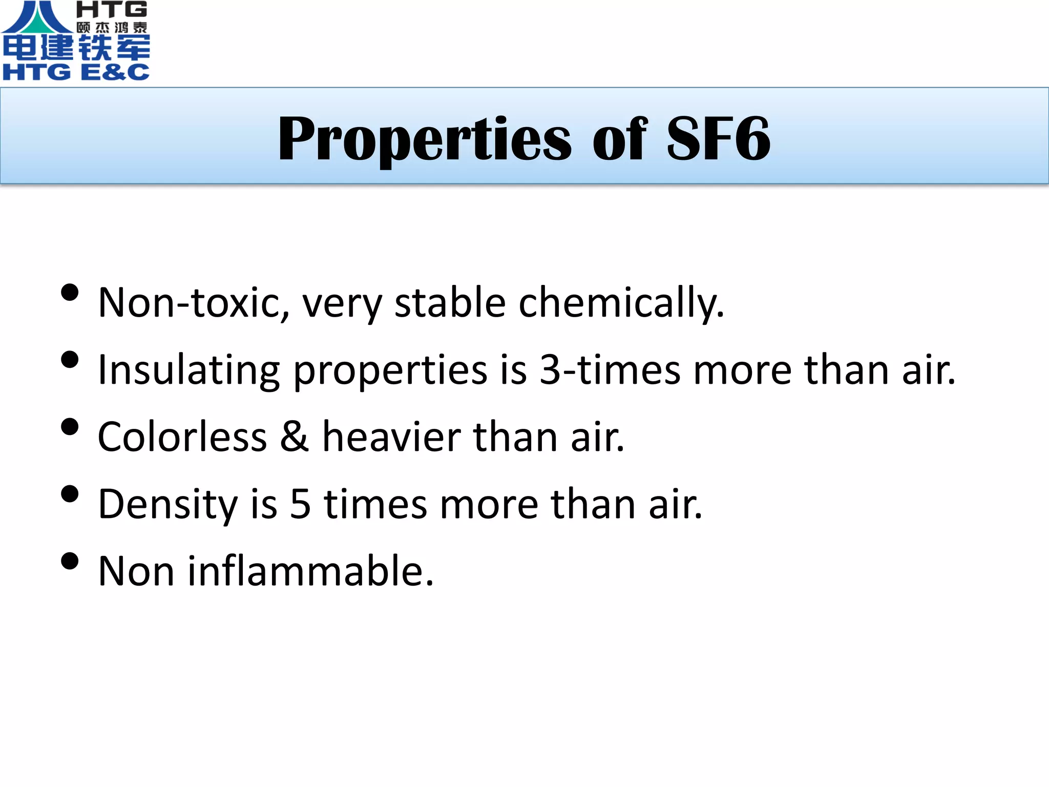
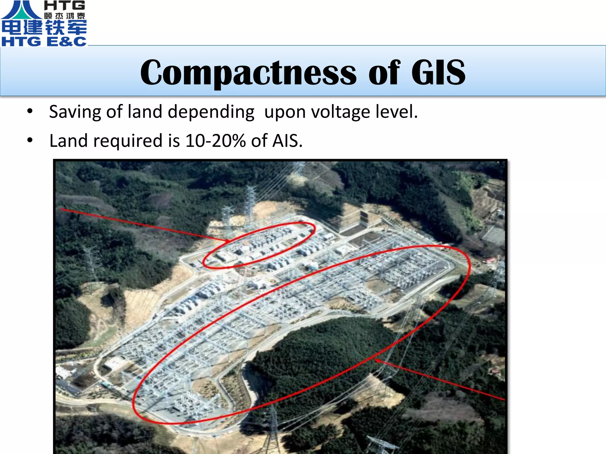
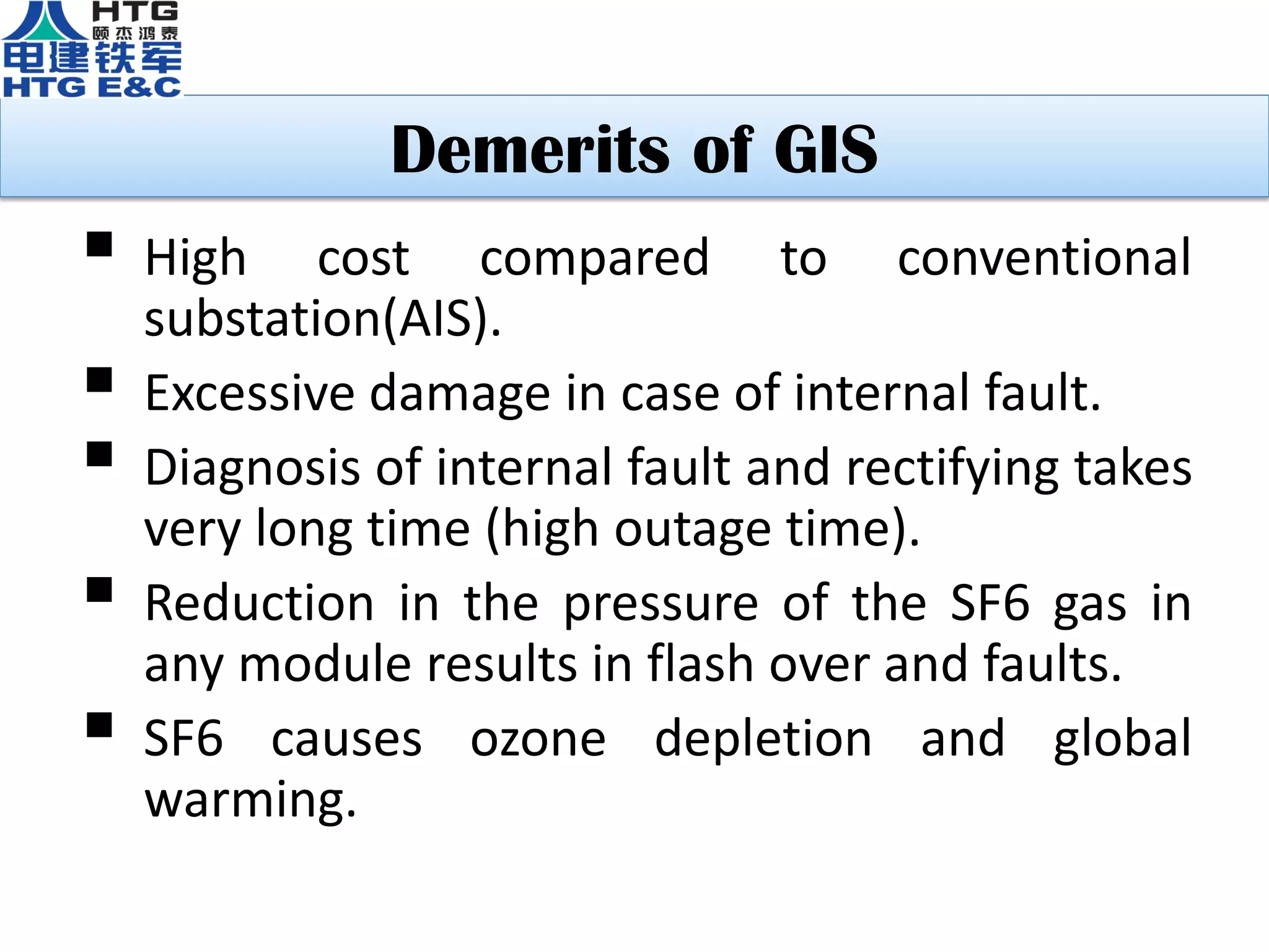
Anbarasu B
Erection and commissioning Engineer
2*600MW ITPCL Power project
Cuddalore-India
SWITCHYARD:
Switchyard will exist at a generating station to
coordinate the exchange of power between the
generators and the transmission lines.
PURPOSE & NECESSITY OF SWITCHYARD
Generatedpowertobeevacuatedtoloadcentersforconsumption.
Generatingstationsarefarfromloadcenters.
Theprocessof
Generation Transmission Consumption/Load center
(in22kV) (in400kV) (in230V)
Air insulated switchyard
Limitation of AIS
 Large dimensions due to statutory clearances
and poor dielectric strength of air.
 Wastage of space.
 Life of steel structures degrades.
 Seismic instability.
 Large planning & execution time.
 Regular maintenance of the substation
required.
Gas Insulated Switchgear
Gas Insulated Switchgear (GIS), where the
conductors and equipments are insulated by
pressurized sulphur hexafluoride gas(SF6).
I. Outdoor GIS (without screen house)
II. Indoor GIS (with screen house)
• Outdoor GIS • Indoor GIS
Merits of GIS
 The space occupied by switch gear is greatly
reduced.
 Totally unaffected by atmospheric conditions.
 Provides high operational reliability.
 Easier to install in difficult site conditions.
 Installation time is lesser than air insulated
switchgear.
TECHNICAL PARAMETERS OF GIS
 Make: Xian XD Electric switchgear Co.,Ltd
 System nominal voltage: 400kV
 Maximum working voltage: 550kV
 Rated current: 4000A
 Rated frequency: 50Hz
 Rated short-circuit breaking current: 63kA for 1sec
 Rated peak withstand current: 170kA
 Rated control voltage: 220V DC
 SF6 Gas pressure at 20°C: 0.5Mpa (Breaker chamber)
0.4Mpa (other gas chamber)
Typical Layout Of 1½ Breaker Scheme
One & Half Breaker Description
 In this two buses are provided.
 These two buses are inter-connected by three circuit
breakers.
 They are designated as 1-52 CB, 2-52 CB, and 3-52 CB.
 Line - 1 is connected in between 1-52 CB & 2-52 CB.
 Line - 2 is connected in between 3-52 CB & 2-52 CB.
 Line-1 having two feeding paths i.e.
A. Via bus-1 & 1-52 CB
B. Via bus-2, 3-52CB & 2-52CB
 Line-2 having two feeding paths i.e.
A. Via bus-2 & 3-52 CB
B. Via bus-1, 1-52CB & 2-52CB
 For interrupting line-1 the 1-52CB and 2-52CB is to be
tripped.
 For interrupting line-2 the 3-52CB and 2-52CB is to be
tripped.
 For any problem in line-1 or line-2 along with main breaker, the
tie breaker (2-52 CB) must trip.
 Normally in all types of busbar configurations one breaker is
sufficient for one feeder.
 Here two feeders are controlled by three breakers.
 So these two feeders controlled by three circuit breakers 1-52
CB,2-52CB & 3-52CB.
It is called one & half breaker system.
 The bay between bus-1 & line-1 is called main bay for feeder-1.
 The bay between line-1 & line-2 is called tie bay for feeder-1 &
2.
 The bay between bus-2 & line-2 is called main bay for feeder-2.
 In this system full dia means 2 feeders controlled by 3 CBs.
 Half dia means 1 feeder controlled by 2 CBs.
GIS EQUIPMENT
• Bus bar
• Circuit breaker
• Disconnecting switch
• Earthing switch
• Current transformer
• Voltage transformer
• SF6 to air termination
• Lightning arrestor
• Capacitance voltage transformer
• Wave trap
Outdoor
equipments
Circuit Breaker
Arcing Chamber
Disconnecting Switches Earthing Switches
CURRENT TRANSFORMER
VOLTAGE TRANSFORMER
SF6 to Air Termination
Properties of SF6
• Non-toxic, very stable chemically.
• Insulating properties is 3-times more than air.
• Colorless & heavier than air.
• Density is 5 times more than air.
• Non inflammable.
Compactness of GIS
• Saving of land depending upon voltage level.
• Land required is 10-20% of AIS.
Concept & Design of GIS
Type of insulator in GIS modules
Bellow and Flange
Bellow Flange
Impact of insulating medium on size of the
switchyard
Voltage Level Bay Width AIS Bay Width GIS
132KV 12m 1m
220KV 18m 2m
400KV 27m 3.6m
765KV 51.5m 6.5m
ERECTION AND COMMISSIONING
 Switchgear assemblies are split into optimized
shipping units for easy transport.
 Quick installation is facilitated because of easy to
handle factory assembled modular units.
 Need of special tools for erection is very less.
 Take less time to check all switching devices and
control circuits.
 All flanges are double checked for tightness.
 All tests are performed in accordance with IEC
standards.
Lifting of equipment by using EOT crane
Step:1 Assemble of circuit breaker an its mechanism box by using
EOT crane.
ERECTION OF GIS EQUIPMENT
Step:2 Erection of walk way over circuit breaker
Step3: Install the current transformer
on the circuit-breakers
Step4: Assemble the disconnectors and
earthing switches on to the current
transformer.
OVERVIEW OF CB, CT & DS AFTER ASSEMBLED
Step5: Install the interconnecting straight enclosures with bellows on to Bus CB
to Tie CB section.
Step6: install straight enclosure on tie breaker section to connect feeder
disconnector.
Step7: Install voltage transformer next to the feeder disconnector with
earth switch
Step8: At last erect the main bus-1 & bus-2 straight enclosure.
MAIN BUS-1 & 2
SECTIONAL VIEW OF GIS
Gantry structure from transformer to GIS
building
View of GIS to LILO
SEGRECATION OF GAS COMPARTMENT
PARTITION CONCEPT
SF6 gas pressure gauge
Life Cycle & Cost of GIS
 Life cycle of GIS is about 50 years, where as for AIS life
cycle is 25 years.
 Approximate cost per bay for 400 KV of GIS & AIS is as
follows:
GIS 7-8 crores
AIS 4-5 crores.
Hence initial cost of GIS is approximately
1.5-1.7 times that of AIS.
 When all merits over the life cycle of GIS is considered
then GIS becomes techno-economic feasible than AIS.
Demerits of GIS
 High cost compared to conventional
substation(AIS).
 Excessive damage in case of internal fault.
 Diagnosis of internal fault and rectifying takes
very long time (high outage time).
 Reduction in the pressure of the SF6 gas in
any module results in flash over and faults.
 SF6 causes ozone depletion and global
warming.
CONCLUSION
 Excellent adoptability due to low space
requirement and high dielectric strength of SF6
gas.
 Short erection and commissioning time.
 Safety to operators
 less requirement of maintenance.
 Initial cost of GIS is higher than AIS, but when all
merits and life cycle cost of GIS is considered the
GIS becomes techno-economic feasible than AIS.
400kV GIS Substation

400kV GIS Substation

  • 1.
    Anbarasu B Erection andcommissioning Engineer 2*600MW ITPCL Power project Cuddalore-India
  • 2.
    SWITCHYARD: Switchyard will existat a generating station to coordinate the exchange of power between the generators and the transmission lines. PURPOSE & NECESSITY OF SWITCHYARD Generatedpowertobeevacuatedtoloadcentersforconsumption. Generatingstationsarefarfromloadcenters. Theprocessof Generation Transmission Consumption/Load center (in22kV) (in400kV) (in230V)
  • 3.
  • 4.
    Limitation of AIS Large dimensions due to statutory clearances and poor dielectric strength of air.  Wastage of space.  Life of steel structures degrades.  Seismic instability.  Large planning & execution time.  Regular maintenance of the substation required.
  • 5.
    Gas Insulated Switchgear GasInsulated Switchgear (GIS), where the conductors and equipments are insulated by pressurized sulphur hexafluoride gas(SF6). I. Outdoor GIS (without screen house) II. Indoor GIS (with screen house)
  • 6.
    • Outdoor GIS• Indoor GIS
  • 7.
    Merits of GIS The space occupied by switch gear is greatly reduced.  Totally unaffected by atmospheric conditions.  Provides high operational reliability.  Easier to install in difficult site conditions.  Installation time is lesser than air insulated switchgear.
  • 8.
    TECHNICAL PARAMETERS OFGIS  Make: Xian XD Electric switchgear Co.,Ltd  System nominal voltage: 400kV  Maximum working voltage: 550kV  Rated current: 4000A  Rated frequency: 50Hz  Rated short-circuit breaking current: 63kA for 1sec  Rated peak withstand current: 170kA  Rated control voltage: 220V DC  SF6 Gas pressure at 20°C: 0.5Mpa (Breaker chamber) 0.4Mpa (other gas chamber)
  • 10.
    Typical Layout Of1½ Breaker Scheme
  • 11.
    One & HalfBreaker Description
  • 12.
     In thistwo buses are provided.  These two buses are inter-connected by three circuit breakers.  They are designated as 1-52 CB, 2-52 CB, and 3-52 CB.  Line - 1 is connected in between 1-52 CB & 2-52 CB.  Line - 2 is connected in between 3-52 CB & 2-52 CB.  Line-1 having two feeding paths i.e. A. Via bus-1 & 1-52 CB B. Via bus-2, 3-52CB & 2-52CB  Line-2 having two feeding paths i.e. A. Via bus-2 & 3-52 CB B. Via bus-1, 1-52CB & 2-52CB  For interrupting line-1 the 1-52CB and 2-52CB is to be tripped.  For interrupting line-2 the 3-52CB and 2-52CB is to be tripped.
  • 13.
     For anyproblem in line-1 or line-2 along with main breaker, the tie breaker (2-52 CB) must trip.  Normally in all types of busbar configurations one breaker is sufficient for one feeder.  Here two feeders are controlled by three breakers.  So these two feeders controlled by three circuit breakers 1-52 CB,2-52CB & 3-52CB. It is called one & half breaker system.  The bay between bus-1 & line-1 is called main bay for feeder-1.  The bay between line-1 & line-2 is called tie bay for feeder-1 & 2.  The bay between bus-2 & line-2 is called main bay for feeder-2.  In this system full dia means 2 feeders controlled by 3 CBs.  Half dia means 1 feeder controlled by 2 CBs.
  • 14.
    GIS EQUIPMENT • Busbar • Circuit breaker • Disconnecting switch • Earthing switch • Current transformer • Voltage transformer • SF6 to air termination • Lightning arrestor • Capacitance voltage transformer • Wave trap Outdoor equipments
  • 15.
  • 16.
  • 17.
  • 18.
  • 19.
    SF6 to AirTermination
  • 20.
    Properties of SF6 •Non-toxic, very stable chemically. • Insulating properties is 3-times more than air. • Colorless & heavier than air. • Density is 5 times more than air. • Non inflammable.
  • 21.
    Compactness of GIS •Saving of land depending upon voltage level. • Land required is 10-20% of AIS.
  • 22.
  • 23.
    Type of insulatorin GIS modules
  • 24.
  • 25.
    Impact of insulatingmedium on size of the switchyard Voltage Level Bay Width AIS Bay Width GIS 132KV 12m 1m 220KV 18m 2m 400KV 27m 3.6m 765KV 51.5m 6.5m
  • 26.
    ERECTION AND COMMISSIONING Switchgear assemblies are split into optimized shipping units for easy transport.  Quick installation is facilitated because of easy to handle factory assembled modular units.  Need of special tools for erection is very less.  Take less time to check all switching devices and control circuits.  All flanges are double checked for tightness.  All tests are performed in accordance with IEC standards.
  • 27.
    Lifting of equipmentby using EOT crane
  • 28.
    Step:1 Assemble ofcircuit breaker an its mechanism box by using EOT crane. ERECTION OF GIS EQUIPMENT
  • 29.
    Step:2 Erection ofwalk way over circuit breaker
  • 30.
    Step3: Install thecurrent transformer on the circuit-breakers Step4: Assemble the disconnectors and earthing switches on to the current transformer.
  • 31.
    OVERVIEW OF CB,CT & DS AFTER ASSEMBLED
  • 32.
    Step5: Install theinterconnecting straight enclosures with bellows on to Bus CB to Tie CB section.
  • 33.
    Step6: install straightenclosure on tie breaker section to connect feeder disconnector.
  • 34.
    Step7: Install voltagetransformer next to the feeder disconnector with earth switch
  • 35.
    Step8: At lasterect the main bus-1 & bus-2 straight enclosure.
  • 36.
  • 37.
  • 38.
    Gantry structure fromtransformer to GIS building
  • 39.
    View of GISto LILO
  • 40.
    SEGRECATION OF GASCOMPARTMENT
  • 41.
  • 42.
  • 43.
    Life Cycle &Cost of GIS  Life cycle of GIS is about 50 years, where as for AIS life cycle is 25 years.  Approximate cost per bay for 400 KV of GIS & AIS is as follows: GIS 7-8 crores AIS 4-5 crores. Hence initial cost of GIS is approximately 1.5-1.7 times that of AIS.  When all merits over the life cycle of GIS is considered then GIS becomes techno-economic feasible than AIS.
  • 44.
    Demerits of GIS High cost compared to conventional substation(AIS).  Excessive damage in case of internal fault.  Diagnosis of internal fault and rectifying takes very long time (high outage time).  Reduction in the pressure of the SF6 gas in any module results in flash over and faults.  SF6 causes ozone depletion and global warming.
  • 45.
    CONCLUSION  Excellent adoptabilitydue to low space requirement and high dielectric strength of SF6 gas.  Short erection and commissioning time.  Safety to operators  less requirement of maintenance.  Initial cost of GIS is higher than AIS, but when all merits and life cycle cost of GIS is considered the GIS becomes techno-economic feasible than AIS.