Download as PDF, PPTX


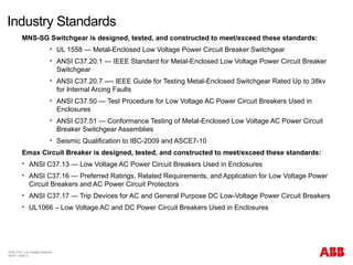

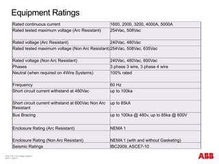
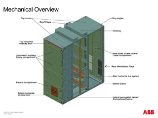
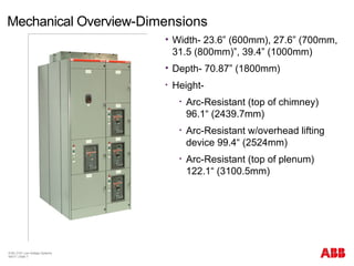


The document summarizes the MNS-SG low voltage switchgear. It discusses the workshop agenda, industry standards the switchgear complies with, its arc-resistant and mechanical features. Key specifications like ratings, dimensions and components are outlined. The switchgear is designed for oil/gas, mining, utilities and other industrial markets.


