07 - ELCB - Fuji Electric
•
3 likes•3,569 views

Catalog thiết bị đóng cắt Fuji Electric - 07 - ELCB ********************************************************************* CTY TNHH HẠO PHƯƠNG - Nhà phân phối chính thức các thiết bị điện công nghiệp và tự động hóa của hãng FUJI ELECTRIC JAPAN tại Việt Nam Xem chi tiết các sản phẩm Fuji Electric tại http://haophuong.com/b1033533/fuji-electric

Recommended
Recommended
More Related Content
What's hot
What's hot (20)
Viewers also liked
Viewers also liked (20)
Similar to 07 - ELCB - Fuji Electric
Similar to 07 - ELCB - Fuji Electric (20)
More from CTY TNHH HẠO PHƯƠNG
More from CTY TNHH HẠO PHƯƠNG (20)
Recently uploaded
Recently uploaded (20)
07 - ELCB - Fuji Electric
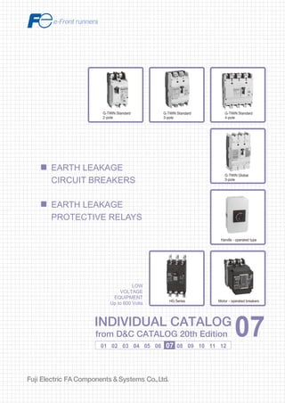
- 1. Information in this catalog is subject to change without notice. 5-7, Nihonbashi Odemma-cho, Chuo-ku, Tokyo, 103-0011, Japan URL http://www.fujielectric.co.jp/fcs/eng INDIVIDUALCATALOGfromD&CCATALOG20thEdition 07 LOW VOLTAGE PRODUCTS Up to 600 Volts Individual catalog No. 01 Magnetic Contactors and Starters Thermal Overload Relays, Solid-state Contactors 02 Industrial Relays, Industrial Control Relays Annunciator Relay Unit, Time Delay Relays Manual Motor Starters and Contactors Combination Starters Pushbuttons, Selector Switches, Pilot Lights Rotary Switches, Cam Type Selector Switches Panel Switches, Terminal Blocks, Testing Terminals Molded Case Circuit Breakers Air Circuit Breakers Earth Leakage Circuit Breakers Earth Leakage Protective Relays Measuring Instruments, Arresters, Transducers Power Factor Controllers Power Monitoring Equipment (F-MPC) Circuit Protectors Low Voltage Current-Limiting Fuses 03 04 05 06 07 08 09 10 HIGH VOLTAGE PRODUCTS Up to 36kV 11 Disconnecting Switches, Power Fuses Air Load Break Switches Instrument Transformers — VT, CT D&C CATALOG DIGEST INDEX AC Power Regulators Noise Suppression Filters Control Power Transformers 12 Vacuum Circuit Breakers, Vacuum Magnetic Contactors Protective Relays Limit Switches, Proximity Switches Photoelectric Switches 01 02 03 04 05 06 07 08 09 10 11 12 INDIVIDUAL CATALOG from D&C CATALOG 20th Edition 07INDIVIDUAL CATALOG from D&C CATALOG 20th Edition 07 EARTH LEAKAGE CIRCUIT BREAKERS EARTH LEAKAGE PROTECTIVE RELAYS G-TWIN Standard 3-pole G-TWIN Standard 4-pole G-TWIN Global 3-pole Handle - operated type Motor - operated breakersHG Series G-TWIN Standard 2-pole LOW VOLTAGE EQUIPMENT Up to 600 Volts 2010-04 PDF FOLS DEC2007
- 2. Ha Noi Office: No. 95 - TT4, My Dinh Urban Area, My Dinh, Nam Tu Liem, Hanoi. Tel: (84 4) 3568 3740 Fax: (84 4) 3568 3741 Cambodia Office: #140, Room 1-B, St430, Sangkat Toul Tompuong II, Khan Chamkamon, PP. Tel: 855 2322 3635 Fax: 855 2322 3645 Head Office: No 88, Vinh Phu 40, Hoa Long, Vinh Phu, Thuan An, Binh Duong. Tel: (84 650) 37 37 619 Fax: (84 650) 37 37 620 1800 6547 THINK TOGETHER Nhà phân phối thiết bị điện công nghiệp hàng đầu Việt Nam T
- 3. 2 G-TWIN Standard series ELCB The Twin Breakers have advanced to an entirely new stage. GLOBAL TWIN History Conforming to IEC & local Standards Conforming to certifications and standards in major world markets Expanded frame sizes in G-TWIN Global Series 2001 -TWIN 2006 G-TWIN1995 Super 601992 Super TWIN1990 TWIN Breaker Compact & High performance Compact models with unified dimensions meeting UL489 480V and IEC 440V requirements G-TWIN Global series ELCB
- 4. 3 FUJI MCCB and ELCB Fuji Electric launched the Twin Breaker Series to world markets in 1990, in which molded case circuit breaker (MCCB) and earth leakage circuit breaker (ELCB) types were unified in external dimensions for the first time in the world. The Twin Breaker Series was highly evaluated and gained strong support, and the concept of Twin Breakers was established as Japan's de facto standards for MCCBs and ELCBs. In 1992, Fuji Electric released the Super Twin Breaker Series, which enabled user installation of internal accessories for the first time in Japan. In 1995, Fuji Electric released the Super 60 Series and advanced modularization via uniform external dimensions. In 2001, Fuji Electric launched the -Twin Series to further advance the miniaturization and modularization of economic types with 100A frame or less as Japan's first multi-standard circuit breakers satisfying domestic and international standards. Since then, Fuji Electric has been making further product improvements by predicting market trends. In recent years, market globalization has increasingly accelerated. At the end of 2004, the Japanese Industrial Standards (JIS) were aligned with the IEC standards, and the globalization in this field has been further accelerated. Based on the Twin Breaker Series, Fuji Electric has expanded the range of its products conforming to and approved by international standards for global markets, always advanced the innovative development of fundamental technologies in response to the market demand, and developed the G-TWIN Series of MCCBs and ELCBs. GLOBAL TWIN Leading the way in user-friendliness Usefulness Ecology Lower environmental impact Advanced green engineering and energy-saving support Conforming to the RoHS Directive GLOBAL TWIN ELCB G-TWIN Standard series ELCB G-TWIN Global series ELCB
- 5. 4 GLOBAL-TWIN Conforming to IEC & local Standards EN Europe Europe EN 60947-2 China GB 14048.2 IEC IEC 60947-2 China GB Japan JIS G-TWIN Standard series CE marking (TÜV) + CCC approved + JIS IEC 60947-2 EN 60947-2 (CE marking) GB 14048.2 (CCC) JIS C 8201-2-1 JIS C 8201-2-2 CE model EN 60947-2 JIS C 8201-2-1 JIS C 8201-2-2 CE marking (TÜV) CCC model GB 14048.2 (China) CCC approved JIS model JIS C 8201-2-1 JIS C 8201-2-2 -TWIN -TWIN -TWIN Ampere frame size (AF) 32 50 63 100 125 160 250 400 630 800 S JIS C 8201-2-1 MCCB JIS C 8201-2-2 ELCB The G-TWIN series is a global breaker series that satisfies all major standards.
- 6. 5 North America UL489 CAN/CSA C22.2 NO.5 NEMA AB1 UL/CSA UL489 model UL 489 CAN/CSA C22.2 NO.5 NEMA AB1 IEC 60947-2 JIS C 8201-2-1 JIS C 8201-2-2 UL mark (cUL) CE marking (TÜV) UL mark (cUL) + CE marking (TÜV) + CCC approved + JIS Ampere frame size (AF) 50 100 125 250 400 630 800 G-TWIN Global series -TWIN North America CE model CCC model JIS model IEC 60947-2 EN 60947-2 (CE marking) GB 14048.2 (CCC) JIS C 8201-2-1 JIS C 8201-2-2 UL 489 CAN/CSA C22.2 NO.5 NEMA AB1 GLOBAL TWIN ELCB
- 7. 6 GLOBAL-TWIN Compact models with unified dimensions meeting UL489 480V and IEC 440V requirements Compact size meeting UL489 480V requirements & same dimensions as MCCB Rated voltage 480V BW250RAGU (W105 x H181 x D68 mm) ELCB Rated voltage 480V (W105 x H181 x D68 mm) MCCB Rated voltage 480V (W105 x H181 x D68 mm) Same dimentions Decrease by 30%! Magnetic yoke arrangement • An increase in the repulsion force of the moving contact at initiation of contact opening Recycling • For easier recycling, all major parts are marked with the names of the materials used. Conforming to the RoHS Directive • Lead-free (Pb-free) solder is used. • Free of hexavalent chromium (Cr6+ -free) (125 to 800AF) Moving contact cover • Arcing prevention at the bottom of moving contact Narrow slit resin • Increased arc voltage due to narrow slit effect • Increased arc voltage and high-speed moving contact opening by ablation effect • Suppression of internal pressure rise by adjusting the narrow slit width Technical innovation Arc and gas flow control technology Effect of “ablation breaking technology” Advanced environmental technology Conforming to the RoHS Directive The G-TWIN Series is designed to lower environmental impact. Compact High performance Ecology ELCB Short-circuit current Current model G-TWIN Arcenergy Moving contact Stationary contact Cadmium-free contact material
- 8. 7 Unifying and reducing the types of internal accessories 32~100AF Usefulness Leading the way in user-friendliness Shunt trip device Auxiliary switch Alarm switch Earth Alarm switch Undervoltage trip device Shunt trip device ELCB ELCB Auxiliary switch Alarm switchUndervoltage trip device Shunt trip device Auxiliary switch Alarm switchUndervoltage trip device 125~250AF 400~800AF • Internal and external accessories A wider range of customer-mountable accessories • Sharing internal accessories of 125/160/250AF breakers. • The number of types of internal accessories of 400/630/800AF has been significantly reduced. GLOBAL TWIN ELCB ELCB Number of types of internal accessories AF -TWIN G-TWIN 125 8 8160/250 8 Number of types of internal accessories AF -TWIN G-TWIN 400 26 6630 800
- 9. 8 3-pole 4-pole Ground fault current protection coordination can be taken easily. New three-phase power supply circuit functions in phase-loss state Adoption of changeover switch for dielectric test High workability can be obtained since the removal of ELCB wiring is not required at dielectric test during inspection (Adopted for 125AF or more). The revised IEC60947-2 stipulates that the ELCB should trip when earth-leakage occurs even in phase loss state in three- phase system. The G-TWIN Series meets this requirement. ELCB internal wiring diagram Easier protection coordination GLOBAL-TWIN Newly developed earth leakage detection circuit ELCB ELCB Main Feeder Branch circuit Branch circuit Time Instantaneus and Time delay type oprerating characteristic Current Feeder Main Main World first ! Four-step changeover switch (I n and tripping time setting) I n (Change over type) Maximum tripping time -TWIN 100/200/500mA 0.1second (fixed) G-TWIN 100/300/500/1000mA 0.1/0.4/1/2second (changeover) Protection device for overload and short-circuit Changeover switch for megger test 5 3 1 LOADLINE 6 4 2 ZCT Trip coil ELR unit Protection device for overload and short-circuit Changeover switch for megger test 5 3 1 LOADLINE N N 6 4 2 ZCT Trip coil ELR unit
- 10. 9 GLOBAL TWIN ELCB Purpose of ELCB installation Prevention of hazards and damage (such as electrical shock, electrical fire, and device damage) that may occur in electrical equipment (as stipulated in IEC 60364). Measures of protection against electrical shock Protection against electric shock (Protective measures are specified in IEC60364-4-41) A. Protection against direct contact Protection of persons from hazards (i.e., electrical shock) that may occur due to touching charged parts of electrical equipment. Use of ELCB with rated sensitive current not exceeding 30mA is recommended as the additional protective device. B. Protection against indirect contact Protection of persons from electrical shock that may occur due to touching exposed conductive parts (such as metal frame of the device) when a fault occurs in electrical equipment. As one of the protective measures, depending on the condition in TT or TN-S system, the automatic cutoff of power supply with ELCB is specified in IEC60364-4-41. For the details of the installation systems and how to apply ELCB, please refer to the following chart and flowchart. L1, L2, L3: Voltage poles, N: Neutral line, PE: Protective conductor 1: A TN-C system has a PEN conductor installed that combines neutral line N and protective conductor PE, and so ELCB cannot be used. (Ground faults cannot be detected.) 2: An IT system is a non-grounded system, and so ELCB cannot be used. (Ground faults cannot be detected.) Types of installation systems in IEC 60364 TN-S System IT SystemTN-C System TT System L1 L2 L3 N PE Exposed-conductive-parts L1 High impedance L2 L3 N PE Exposed-conductive-parts L1 Exposed-conductive-parts L2 L3 PEN PE N L1 L2 L3 N PE Exposed-conductive-parts Why ELCB? Supply circuit to stationary device? Flowchart for considering protection against indirect contact using automatic cutoff of power supply TN-S system or TT system? Can Ia be cut off in 5s or less? Can Ia be cut off in 5s max.? Ra x Ia ≦ 50V? Note 1: The formula 10 x In is a rough guide to the current value for the overcurrent trip device to automatically cut off in 5s or less. Max. breaking time in TN system (IEC 60364, table 41A) Uo(V) Breaking time (s) 120 0.8 230 0.4 277 0.4 400 0.2 400 0.1 If la 10 x In, then Yes. Can la be cut off in the time given in table in IEC 60364? Check the operating characteristics curve for the MCCB. If la 10 x In, then Yes. (Refer to note 1.) Check the operating characteristics curve for the MCCB. If la 10 x In, then Yes. (Refer to note 1.) Can Ra be decreased? IEC 60364-4-41 413.1.3 Zs x Ia ≦ Uo Uo:Normal line-to-earth voltage Zs:Fault loop comprising impedance Rb:Earth electrode resistance Ra:Minimum contact resistance with earth Ia: Ground fault current In; Rated current of MCCB IEC 60364-4-41 413.1.4 Ia = Uo Rb+Ra MCCB can be used. MCCB can be used. ELCB must be used. ELCB is not applicable for TN-C. ELCB must be used. Calculate the fault current la. Calculate the fault current la. START YES TN-S System TT System NO YES YES YES YES YES NO NO NO NO NO L1 L2 L3 N A B
- 11. 10 Fuji Electric FA components Systems Co., Ltd./D C Catalog Information subject to change without notice n Type of ELCBs HG Series Earth Leakage Protective Relays BRR,RRD,EL Series G-TWIN Series Line protection Page Feature Type 07/04 · Models from 3A to 800A · ELCB and MCCB have the same dimensions. · Conforming to international standard IEC/EN(CE)/GB(CCC)/JIS · Most accessories can be installed by the user. EW ①② A G- ③④⑤ AF ① Breaking capacity ② Pole ③ Rated current ④ Rated sensitive current ⑤ 32 A 2P 003=3A A=15mA 50 E 3P ・ B=30mA 63 J 4P ・ C=100mA 100 S ・ J=Changeover type K=Changeover type125 R 800=800A 160 H 250 400 630 800 Motor protection Page Feature Type 07/18 · Models from 0.7A to 225A · Line Motor protection · Conforming to international standard IEC/EN(CE)/GB(CCC)/JIS EW ①② A M- ③④⑤ AF ① Breaking capacity ② Pole ③ Rated current ④ Rated sensitive current ⑤ 32 E 3P 0P7=0.7A B=30mA 50 J ・ C=100mA 63 S ・ J=Changeover type K=Changeover type100 R ・ 125 225=225A 250 UL489 Listed Page Feature Type 07/13 · Models from 3A to 630A · Conforming to international standard UL/CSA/IEC/EN(CE)/GB(CCC)/JIS EW ①② A G U- ③④⑤ AF ① Breaking capacity ② Pole ③ Rated current ④ Rated sensitive current ⑤ 50 E 2P 003=3A B=30mA 100 J 3P ・ D=50mA 125 S ・ K=Changeover type 250 R ・ 400 H 630=630A 630 Line protection Page Feature Type 07/88 · Models from 15A to 225A HG ①② B/ ③④ AF ① Pole ② Rated current ③ Rated sensitive current ⑤ 5=50AF 3=3P 15=15A 30MA=30mA fixed 10=10AF : CO=Changeover type 20=225AF 225=225A Page Feature Type 07/105 Relay and sensor-Unit type · BRR series Relay and sensor-Separate type · RRD series · EL series BRR ①② N (H) RRD ①② Sensor hole ① Sensitive current ② Sensor hole ① Pole ② 0=φ10mm 1=30mA 25=φ25mm P0=Pass-through type 1=φ25mm 9=100mA 40=φ40mm 2=φ40mm 2=200mA 60=φ60mm 4=400A 5=500mA 90=φ90mm (Rated current) 120=φ120mm Rated current ① Pole ② EL ①② 6A=600A Z3=3Pole Sensor hole ① Pole ② 8A=800A Z4=4Pole 25=φ25mm P0=Pass-through type 10A=1000A 40=φ40mm 12A=1200A 60=φ60mm 90=φ90mm 120=φ120mm Earth Leakage Circuit Breakers G-TWIN series Type of ELCBs
- 12. 11 07 Fuji Electric FA components Systems Co., Ltd./D C Catalog Information subject to change without notice Rated interrupting capacity IEC60947-2 Icu (kA) Current (A) 3 5 10 15 32 50 63 100 125 160 250 400 630 800 440VAC 1.5 2.5 7.5 10 18 30 36 50 70 Rated interrupting capacity IEC60947-2 Icu (kA) Current (A) 0.7 1.4 10 16 32 63 90 100 125 225 440VAC 1.5 2.5 7.5 10 18 30 50 Rated interrupting capacity UL489 (kA) Current (A) 3 15 32 50 63 100 125 250 400 630 800 480VAC 30 35 50 65 240VAC 14 50 100 Rated interrupting capacity Icu (kA) Current (A) 15 30 50 60 100 125 225 65 Type Diameter of sensor hole (mm) Rated current (A) 10 25 40 60 90 120 400 600 800 1000 1200 BRR EL RRD Earth Leakage Circuit Breakers G-TWIN series Type of ELCBs
- 13. 07 Earth Leakage Circuit Breakers Earth Leakage Protective Relays Page Earth Leakage Circuit Breakers G-TWIN series List of products..............................................................................................................07/1 Type number nomenclature...........................................................................................07/2 Quick reference guide....................................................................................................07/4 Mounting modifications................................................................................................07/22 Terminal connection.....................................................................................................07/24 Wire size and terminal.................................................................................................07/25 Type number................................................................................................................07/29 Arc space.....................................................................................................................07/35 Dimensions..................................................................................................................07/36 Characteristic curves...................................................................................................07/51 Accessories.................................................................................................................07/57 HG series List of products..............................................................................................................07/1 Quick reference guide..................................................................................................07/88 Mounting modifications................................................................................................07/89 Terminal connection.....................................................................................................07/90 Type number nomenclature.........................................................................................07/91 Type number................................................................................................................07/92 Dimensions..................................................................................................................07/93 Characteristic curves...................................................................................................07/94 Accessories.................................................................................................................07/95 Earth Leakage Protective Relays Description/Selection guide.......................................................................................07/105 Type number nomenclature/Specifications................................................................07/106 Wire size....................................................................................................................07/107 Dimensions................................................................................................................07/112 Wiring diagrams.........................................................................................................07/115
- 14. MINIMUM ORDERS Orders amounting to less than ¥10,000 net per order will be charged as ¥10,000 net per order plus freight and other charges. WEIGHTS AND DIMENSIONS Weights and dimensions appearing in this catalog are the best information available at the time of going to press. FUJI ELECTRIC FA has a policy of continuous product improvement, and design changes may make this information out of date. Please confirm such details before planning actual construction. INFORMATION IN THIS CATALOG IS SUBJECT TO CHANGE WITHOUT NOTICE.
- 15. 07/1 07 Fuji Electric FA components Systems Co., Ltd./D C Catalog Information subject to change without notice G-TWIN Standard Series (IEC/EN/GB/JIS conformed) Line protection • 2-pole AC230V (Icu) EW32 EW50 EW100 2.5kA AAG-2P AAG-2P 10kA EAG-2P • 2-pole AC230V (Icu) EW100 10kA EAGU-2P • 3-pole AC415V (Icu) EW50 EW100 EW125 EW250 EW400 EW630 10kA RAGU-3P EAGU-3P 30kA JAGU-3P JAGU-3P 36kA SAGU-3P 50kA RAGU-3P RAGU-3P RAGU-3P RAGU-3P 70kA HAGU-3P HG Series Line protection (3-pole) AC415V (Icu) 50AF 100AF 225AF 65kA HG53B HG103B HG203B Earth Leakage Circuit Breakers List of products Motor protection • 3-pole AC415V (Icu) EW32 EW50 EW63 EW100 EW125 EW250 1.5kA EAM-3P 2.5kA SAM-3P EAM-3P EAM-3P 7.5kA SAM-3P SAM-3P 10kA EAM-3P 18kA EAM-3P 30kA JAM-3P JAM-3P 50kA RAM-3P RAM-3P • 3-pole AC415V (Icu) EW32 EW50 EW63 EW100 EW125 EW160 EW250 EW400 EW630 EW800 1.5kA EAG-3P 2.5kA SAG-3P EAG-3P EAG-3P 7.5kA SAG-3P SAG-3P 10kA RAG-3P RAG-3P EAG-3P 18kA EAG-3P EAG-3P 30kA JAG-3P JAG-3P JAG-3P EAG-3P 36kA SAG-3P SAG-3P SAG-3P SAG-3P EAG-3P EAG-3P 50kA RAG-3P RAG-3P RAG-3P RAG-3P RAG-3P RAG-3P 70kA HAG-3P HAG-3P HAG-3P • 4-pole AC415V (Icu) EW125 EW160 EW250 EW400 30kA JAG-4P JAG-4P JAG-4P 36kA SAG-4P SAG-4P SAG-4P 50kA RAG-4P RAG-4P RAG-4P RAG-4P 70kA HAG-4P G-TWIN Global Series (IEC/EN/GB/JIS/UL/CSA conformed) Line protection
- 16. 07/2 Fuji Electric FA components Systems Co., Ltd./D C Catalog Information subject to change without notice Type number nomenclature Earth Leakage Circuit Breakers G-TWIN series Type number nomenclature Rated current See page 07/29. Rated sensitive current A: 15mA J: 100/300/500/1000mA B: 30mA K: 100/200mA C: 100mA 100/200/500mA D: 50mA 100/200/500/1000mA No. of poles 2P: 2-pole 3P: 3-pole 4P: 4-pole G-TWIN series Blank: Standard U: Global Model G: Line protection M: Motor protection Breaking capacity Rated breaking capacity Icu (440V AC) *(at 230V AC) 32AF 50AF 63AF 100AF 125AF 160AF 250AF 400AF 630AF 800AF AA 2.5kA* 2.5kA* – 5kA* – – – – – – EA 1.5kA 2.5kA 2.5kA 10kA – 18kA 18kA 30kA 36kA 36kA JA – – – – 30kA 30kA 30kA – – – SA 2.5kA 7.5kA 7.5kA – 36kA 36kA 36kA 36kA – – RA – 10kA 10kA – 50kA 50kA 50kA 50kA 50kA 50kA HA – – – – – – – 70kA 70kA 70kA Frame size 32: 32AF 63: 63AF 125: 125AF 250: 250AF 630: 630AF 50: 50AF 100: 100AF 160: 160AF 400: 400AF 800: 800AF Series EW: G-TWIN series ELCB EW 250 EA G - 3P 225 B X Mounting and connection • Standard type Blank: Front mounting, front connection X: Front mounting, rear connection E: Flush mounting, rear connection Y: Flush mounting, top buttom connection P: Plug-in mounting Terminal combination (Global type) Terminal position Applicable breaker type Code Blank Blank SB SF S3 S4 S5 S6 S7 S8 Line Screw Flat teminal Block terminal Flat teminal Screw Flat teminal Screw Block terminal Flat teminal Block terminal Load Screw Flat teminal Block terminal Flat teminal Flat terminal Screw Block terminal Screw Block terminal Flat terminal EW50, 100 ● – – ● ● ● – – – – EW125, 250 ● – ● ● ● ● ● ● ● ● EW400, 630 – ● ● – – – – – ● ●
- 17. 07/3 07 Fuji Electric FA components Systems Co., Ltd./D C Catalog Information subject to change without notice Auxiliary switch* W: Standard SPDT V: Standard 2PDT 1: For low level circuit SPDT 2: For low level circuit 2PDT Alarm switch* K: Standard SPDT J: Standard 2PDT 8: For low level circuit SPDT 9: For low level circuit 2PDT Undervoltage trip device (Internal)* • 125/160/250AF : DC24V : DC48V : DC100-110V : DC125V / AC100-110V : AC110-130V : AC200-240V : AC277V : AC380-415V Undervoltage trip device (External)* • 32/50/63/100AF : DC24V : DC100-110V : AC100V (50Hz) / AC100-110V (60Hz) : AC200V (50Hz) / AC200-220V (60Hz) : AC400V (50Hz) / AC400-440V (60Hz) Connection method (internal accessories) Blank: Lead-wire system A: Terminal block system W K F R A Q2 M UC * For the available configuration of accessory, see page 07/62. Shunt trip device (Internal)* • 125/160/250AF • 400/630/800AF : AC/DC24V : AC/DC24-48V : AC/DC48V : AC100-240V / DC100-220V : AC100-120V / DC100-110V : AC277V : AC120-130V : AC380-550V : AC200-240V / DC200-220V : AC277V : AC380-440V : AC440-480V : AC500-550V Shunt trip device (External)* • 32/50/63/100AF : DC24V : DC100-110V : AC100 (50Hz) / AC100-110V (60Hz) : AC200 (50Hz) / AC200-220V (60Hz) : AC400 (50Hz) / AC400-440V (60Hz) Pad locking device Q2: Plate type With motor operating device (32 - 100AF) : DC100V AC100-110V AC200-220V Enclosure UC: Standard UV: Dust-proof UW: Rain-proof • 400/630/800AF : AC/DC24V : AC/DC48V : AC/DC100-110V : AC120-130V / DC125V : AC200-240V / DC200-220V : AC277V : AC380-480V Earth Leakage Circuit Breakers G-TWIN series Type number nomenclature
- 18. 07/4 Fuji Electric FA components Systems Co., Ltd./D C Catalog Information subject to change without notice Ampere frame 32A Type EW32AAG EW32EAG EW32SAG Pole 2 3 3 3 Rated current Reference amb. temp. (40°C) In(A) 5, 10, 15, 20, 30, 32 5, 10, 15, 20, 30, 32 5, 10, 15, 20, 30, 32 3, 5, 10, 15, 20, 30, 32 Rated impulse withstand voltage Uimp(kV) 2.5 4 4 4 Isolation compliant Rated voltage Ue (AC V) 100-230 100-230 100-230-440 100-230-440 Rated sensitive current (mA) 15, 30, 100 15, 30, 100 15, 30, 100 30, 100/200/500 changeover Tripping time (s) 0.1 or less 0.1 or less 0.1 or less 0.1 or less Rated breaking capacity Icu/Ics (kA) IEC 60947-2 EN 60947-2 JIS C 8201-2-2 AC 440V − − 1.5/1 2.5/2 415V − − 1.5/1 2.5/2 400V − − 1.5/1 2.5/2 380V − − 1.5/1 2.5/2 230V 2.5/2 2.5/2 2.5/2 5/3 200V 2.5/2 2.5/2 2.5/2 5/3 100V 2.5/2 5/3 5/3 5/3 GB14048.2 AC 400V − − 1.5/1 2.5/2 230V 2.5/2 2.5/2 2.5/2 5/3 Conforming to standards CE Marking (TÜV) (TÜV) (TÜV) (TÜV) CCC certificate Electrical Appliance and Material Safety Law *1 Dimensions (mm) a 50 75 75 75 b 100 100 100 c 60 60 60 d 84 84 84 Mass (kg) 0.4 0.5 0.5 0.6 Tripping device Hydraulic-magnetic Front mounting, front connection No-mark Front mounting, rear connection X Flush mounting, front connection E Flush mounting, top bottom connection Y Plug-in mounting P IEC 35mm wide rail mounting No-mark Internal accessories Page 07/57 Alarm switch K Auxiliary switch W Undervoltage trip R Shunt trip F Earth alarm switch L − − − − External accessories Page 07/60 Handle padlocking device Cap type QN Handle padlocking device Plate type Q2 Operating handle N-type N Operating handle V-type V Terminal cover Short BT S Terminal cover Long BT L Insulation barrier Interphase BP Earth BL Handle locking cover L1 Flat terminal SS Block terminal SL − − − − : Approved : Available –: Not available : Factory-mounted accessory Note: *1 Electrical Appliance and Material Safety Law of Japan G-TWIN Standard Series c a d b Earth Leakage Circuit Breakers G-TWIN series Quick reference guide Rated voltage (V) Operational voltage range (V) 100–230 80–264 100–230–440 80–484
- 19. 07/5 07 Fuji Electric FA components Systems Co., Ltd./D C Catalog Information subject to change without notice Ampere frame 50A Type EW50AAG EW50EAG EW50SAG EW50RAG Pole 2 3 3 3 3 Rated current Reference amb. temp. (40°C) In(A) 5, 10, 15, 20, 30, 32, 40, 50 5, 10, 15, 20, 30, 32, 40, 50 5, 10, 15, 20, 30, 32, 40, 50 10, 15, 20, 30, 32, 40, 50 Rated impulse withstand voltage Uimp(kV) 2.5 4 6 6 6 Isolation compliant Rated voltage Ue (AC V) 100-230 100-230-440 100-230-440 100-230-440 Rated sensitive current (mA) 15, 30, 100 15, 30, 100/200 changeover 30, 100/200/500 changeover 30, 100/200/500 changeover Tripping time (s) 0.1 or less 0.1 or less 0.1 or less 0.1 or less Rated breaking capacity Icu/Ics (kA) IEC 60947-2 EN 60947-2 JIS C 8201-2-2 AC 440V − 2.5/2 7.5/4 10/5 415V − 2.5/2 7.5/4 10/5 400V − 2.5/2 7.5/4 10/5 380V − 2.5/2 7.5/4 10/5 230V 2.5/2 5/3 10/5 25/13 200V 2.5/2 5/3 10/5 25/13 100V 2.5/2 5/3 5/3 10/5 25/13 GB14048.2 AC 400V − 2.5/2 7.5/4 10/5 230V 2.5/2 5/3 10/5 25/13 Conforming to standards CE Marking (TÜV) (TÜV) (TÜV) (TÜV) CCC certificate Electrical Appliance and Material Safety Law *1 Dimensions (mm) a 50 75 75 75 75 b 100 100 100 100 c 60 60 60 60 d 84 84 84 84 Mass (kg) 0.4 0.6 0.6 0.6 0.6 Tripping device Hydraulic-magnetic Front mounting, front connection No-mark Front mounting, rear connection X Flush mounting, front connection E Flush mounting, top bottom connection Y Plug-in mounting P IEC 35mm wide rail mounting No-mark Internal accessories Page 07/57 Alarm switch K Auxiliary switch W Undervoltage trip R Shunt trip F Earth alarm switch L − − − − External accessories Page 07/60 Handle padlocking device Cap type QN Handle padlocking device Plate type Q2 Operating handle N-type N Operating handle V-type V Terminal cover Short BT S Terminal cover Long BT L Insulation barrier Interphase BP Earth BL Handle locking cover L1 Flat terminal SS Block terminal SL − − − − : Approved : Available –: Not available : Factory-mounted accessory Note: *1 Electrical Appliance and Material Safety Law of Japan c a d b G-TWIN Standard Series Earth Leakage Circuit Breakers G-TWIN series Quick reference guide Rated voltage (V) Operational voltage range (V) 100–230 80–264 100–230–440 80–484
- 20. 07/6 Fuji Electric FA components Systems Co., Ltd./D C Catalog Information subject to change without notice G-TWIN Standard Series Ampere frame 63A Type EW63EAG EW63SAG EW63RAG Pole 3 3 3 Rated current Reference amb. temp. (40°C) In(A) 60, 63 60, 63 60, 63 Rated impulse withstand voltage Uimp(kV) 6 6 6 Isolation compliant Rated voltage Ue (AC V) 100-230-440 100-230-440 100-230-440 Rated sensitive current (mA) 15, 30, 100/200 changeover 30, 100/200/500 changeover 30, 100/200/500 changeover Tripping time (s) 0.1 or less 0.1 or less 0.1 or less Rated breaking capacity Icu/Ics (kA) IEC 60947-2 EN 60947-2 JIS C 8201-2-2 AC 440V 2.5/2 7.5/4 10/5 415V 2.5/2 7.5/4 10/5 400V 2.5/2 7.5/4 10/5 380V 2.5/2 7.5/4 10/5 230V 5/3 10/5 25/13 200V 5/3 10/5 25/13 100V 5/3 10/5 25/13 GB14048.2 AC 400V 2.5/2 7.5/4 10/5 230V 5/3 10/5 25/13 Conforming to standards CE Marking (TÜV) (TÜV) (TÜV) CCC certificate Electrical Appliance and Material Safety Law *1 Dimensions (mm) a 75 75 75 b 100 100 100 c 60 60 60 d 84 84 84 Mass (kg) 0.6 0.6 0.6 Tripping device Hydraulic-magnetic Front mounting, front connection No-mark Front mounting, rear connection X Flush mounting, front connection E Flush mounting, top bottom connection Y Plug-in mounting P IEC 35mm wide rail mounting No-mark Internal accessories Page 07/57 Alarm switch K Auxiliary switch W Undervoltage trip R Shunt trip F Earth alarm switch L – – – External accessories Page 07/60 Handle padlocking device Cap type QN Handle padlocking device Plate type Q2 Operating handle N-type N Operating handle V-type V Terminal cover Short BT S Terminal cover Long BT L Insulation barrier Interphase BP Earth BL Handle locking cover L1 Flat terminal SS Block terminal SL − − − : Approved : Available –: Not available : Factory-mounted accessory Note: *1 Electrical Appliance and Material Safety Law of Japan c a d b Earth Leakage Circuit Breakers G-TWIN series Quick reference guide Rated voltage (V) Operational voltage range (V) 100–230 80–264 100–230–440 80–484
- 21. 07/7 07 Fuji Electric FA components Systems Co., Ltd./D C Catalog Information subject to change without notice G-TWIN Standard Series Ampere frame 100A Type EW100AAG EW100EAG Pole 3 2 3 Rated current Reference amb. temp. (40°C) In(A) 60, 63, 75, 100 50, 60, 63, 75, 100 50, 60, 63, 75, 100 Rated impulse withstand voltage Uimp(kV) 4 4 6 Isolation compliant Rated voltage Ue (AC V) 100-230 100-230 100-230-400 Rated sensitive current (mA) 30, 100/200/500 changeover 30, 100/200 changeover 30, 100/200/500 changeover Tripping time (s) 0.1 or less 0.1 or less 0.1 or less Rated breaking capacity Icu/Ics (kA) IEC 60947-2 EN 60947-2 JIS C 8201-2-2 AC 440V − – 10/5 415V − – 10/5 400V − – 10/5 380V – – 10/5 230V 5/3 10/5 25/13 200V 5/3 10/5 25/13 100V 5/3 10/5 25/13 GB14048.2 AC 400V – – 10/5 230V 5/3 10/5 25/13 Conforming to standards CE Marking (TÜV) (TÜV) (TÜV) CCC certificate Electrical Appliance and Material Safety Law *1 Dimensions (mm) a 75 75 75 b 100 100 100 c 60 60 60 d 84 84 84 Mass (kg) 0.6 0.6 0.6 Tripping device Thermal -magnetic Front mounting, front connection No-mark Front mounting, rear connection X Flush mounting, front connection E Flush mounting, top bottom connection Y Plug-in mounting P IEC 35mm wide rail mounting No-mark Internal accessories Page 07/57 Alarm switch K Auxiliary switch W Undervoltage trip R Shunt trip F Earth alarm switch L – – – External accessories Page 07/60 Handle padlocking device Cap type QN Handle padlocking device Plate type Q2 Operating handle N-type N Operating handle V-type V Terminal cover Short BT S Terminal cover Long BT L Insulation barrier Interphase BP Earth BL Handle locking cover L1 Flat terminal SS Block terminal SL − − − : Approved : Available –: Not available : Factory-mounted accessory Note: *1 Electrical Appliance and Material Safety Law of Japan c a d b Earth Leakage Circuit Breakers G-TWIN series Quick reference guide Rated voltage (V) Operational voltage range (V) 100–230 80–264 100–230–440 80–484
- 22. 07/8 Fuji Electric FA components Systems Co., Ltd./D C Catalog Information subject to change without notice G-TWIN Standard Series c a d b Earth Leakage Circuit Breakers G-TWIN series Quick reference guide Ampere frame 125A Type EW125JAG EW125SAG EW125RAG Pole 3 4 3 4 3 4 Rated current Reference amb. temp. (40°C) In(A) 15, 20, 30, 40, 50, 60, 75, 100, 125 Rated impulse withstand voltage Uimp(kV) 6 6 6 Isolation compliant Rated voltage Ue (AC V) 100-230-440 Type of earth leakage trip action AC type Instantaneous trip type Rated sensitive current (mA) 30 Tripping time (s) 0.1 or less Instantaneous/time- delay trip type Rated sensitive current (mA) 100/300/500/1000 changeover Tripping time (s) 0.1/0.4/1/2 changeover Inertia non-tripping time (s) (2l n) 0/0.2/0.5/1 Rated breaking capacity Icu/Ics (kA) IEC60947-2 EN60947-2 JISC8201-2-2 AC 440V 30/15 36/18 50/25 415V 30/15 36/18 50/25 400V 30/15 36/18 50/25 380V 30/15 36/18 50/25 230V 50/25 85/43 100/50 200V 50/25 85/43 100/50 100V 50/25 85/43 100/50 GB14048.2 AC 400V 30/15 36/18 50/25 230V 50/25 85/43 100/50 Conforming to standards CE Marking (TÜV) (TÜV) (TÜV) CCC certificate Electrical Appliance and Material Safety Law *1 (except for 125A) (except for 125A) (except for 125A) Dimensions (mm) a 90 120 90 120 90 120 b 155 155 155 c 68 68 68 d 95 95 95 Mass (kg) 1.3 1.7 1.2 1.6 1.3 1.7 Tripping device Thermal-magnetic Front mounting, front connection No-mark Front mounting, rear connection X Flush mounting, front connection E Plug-in mounting P – – – Internal accessories Page 07/58 Alarm switch K Auxiliary switch W Undervoltage trip R Shunt trip F Earth alarm switch L External accessories Page 07/60 Handle padlocking device Cap type Q1 Handle padlocking device Plate type Q2 Operating handle N-type N Operating handle V-type V Terminal cover Short BT S Terminal cover Long BT L Insulation barrier Interphase BP Handle locking cover L1 Flat terminal SS Block terminal SL : Approved : Available –: Not available : Factory-mounted accessory Note: *1 Electrical Appliance and Material Safety Law of Japan Rated voltage (V) Operational voltage range (V) 100–230–440 80–484
- 23. 07/9 07 Fuji Electric FA components Systems Co., Ltd./D C Catalog Information subject to change without notice G-TWIN Standard Series Earth Leakage Circuit Breakers G-TWIN series Quick reference guide Ampere frame 160A Type EW160EAG EW160JAG EW160SAG EW160RAG Pole 3 3 4 3 4 3 4 Rated current Reference amb. temp. (40°C) In(A) 125, 150, 160 Rated impulse withstand voltage Uimp(kV) 6 6 6 6 Isolation compliant Rated voltage Ue (AC V) 100-230-440 Type of earth leakage trip action AC type Instantaneous trip type Rated sensitive current (mA) 30 Tripping time (s) 0.1 or less Instantaneous/time- delay trip type Rated sensitive current (mA) 100/300/500/1000 changeover Tripping time (s) 0.1/0.4/1/2 changeover Inertia non-tripping time (s) (2l n) 0/0.2/0.5/1 Rated breaking capacity Icu/Ics (kA) IEC60947-2 EN60947-2 JISC8201-2-2 AC 440V 18/9 30/15 36/18 50/25 415V 18/9 30/15 36/18 50/25 400V 18/9 30/15 36/18 50/25 380V 18/9 30/15 36/18 50/25 230V 36/18 50/25 85/43 100/50 200V 36/18 50/25 85/43 100/50 100V 36/18 50/25 85/43 100/50 GB14048.2 AC 400V 18/9 30/15 36/18 50/25 230V 36/18 50/25 85/43 100/50 Conforming to standards CE Marking certified (TÜV) (TÜV) (TÜV) (TÜV) (TÜV) CCC certificate Dimensions (mm) a 105 105 140 105 140 105 140 b 165 165 165 165 c 68 68 68 68 d 95 95 95 95 Mass (kg) 1.8 1.8 2.3 1.8 2.3 1.8 2.3 Tripping device Thermal-magnetic Front mounting, front connection No-mark Front mounting, rear connection X Flush mounting, front connection E Plug-in mounting P – – – Internal accessories Page 07/58 Alarm switch K Auxiliary switch W Undervoltage trip R Shunt trip F Earth alarm switch L External accessories Page 07/60 Handle padlocking device Cap type Q1 Handle padlocking device Plate type Q2 Operating handle N-type N Operating handle V-type V Terminal cover Short BT S Terminal cover Long BT L Insulation barrier Interphase BP Handle locking cover L1 Flat terminal SS Block terminal SL : Approved : Available –: Not available : Factory-mounted accessory Note: *1 Electrical Appliance and Material Safety Law of Japan c a d b Rated voltage (V) Operational voltage range (V) 100–230–440 80–484
- 24. 07/10 Fuji Electric FA components Systems Co., Ltd./D C Catalog Information subject to change without notice G-TWIN Standard Series Earth Leakage Circuit Breakers G-TWIN series Quick reference guide Ampere frame 250A Type EW250EAG EW250JAG EW250SAG EW250RAG Pole 3 3 4 3 4 3 4 Rated current Reference amb. temp. (40°C) In(A) 175, 200, 225, 250 175,200,225 175,200,225,250 175,200,225 175,200,225,250 175,200,225 Rated impulse withstand voltage Uimp(kV) 6 6 6 6 Isolation compliant Rated voltage Ue (AC V) 100-230-440 Type of earth leakage trip action AC type Instantaneous trip type Rated sensitive current (mA) 30 Tripping time (s) 0.1 or less Instantaneous/time- delay trip type Rated sensitive current (mA) 100/300/500/1000 changeover Tripping time (s) 0.1/0.4/1/2 changeover Inertia non-tripping time (s) (2l n) 0/0.2/0.5/1 Rated breaking capacity Icu/Ics (kA) IEC60947-2 EN60947-2 JISC8201-2-2 AC 440V 18/9 30/15 36/18 50/25 415V 18/9 30/15 36/18 50/25 400V 18/9 30/15 36/18 50/25 380V 18/9 30/15 36/18 50/25 230V 36/18 50/25 85/43 100/50 200V 36/18 50/25 85/43 100/50 100V 36/18 50/25 85/43 100/50 GB14048.2 AC 400V 18/9 30/15 36/18 50/25 230V 36/18 50/25 85/43 100/50 Conforming to standards CE Marking (TÜV) (TÜV) (TÜV) (TÜV) CCC certificate Dimensions (mm) a 105 105 140 105 140 105 140 b 165 165 165 165 c 68 68 68 68 d 95 95 95 95 Mass (kg) 1.8 1.8 2.3 1.8 2.3 1.8 2.3 Tripping device Thermal-magnetic Front mounting, front connection No-mark Front mounting, rear connection X Flush mounting, front connection E Plug-in mounting P – – – Internal accessories Page 07/58 Alarm switch K Auxiliary switch W Undervoltage trip R Shunt trip F Earth alarm switch L External accessories Page 07/60 Handle padlocking device Cap type Q1 Handle padlocking device Plate type Q2 Operating handle N-type N Operating handle V-type V Terminal cover Short BT S Terminal cover Long BT L Insulation barrier Interphase BP Handle locking cover L1 Flat terminal SS Block terminal SL : Approved : Available –: Not available : Factory-mounted accessory Note: *1 Electrical Appliance and Material Safety Law of Japan c a d b Rated voltage (V) Operational voltage range (V) 100–230–440 80–484
- 25. 07/11 07 Fuji Electric FA components Systems Co., Ltd./D C Catalog Information subject to change without notice G-TWIN Standard Series Earth Leakage Circuit Breakers G-TWIN series Quick reference guide Ampere frame 400A Type EW400EAG EW400SAG EW400RAG EW400HAG Pole 3 3 3 4 3 4 Rated current Reference amb. temp. (40°C) In(A) 250, 300, 350, 400 Rated impulse withstand voltage Uimp(kV) 6 6 6 6 Isolation compliant Rated voltage Ue (AC V) IEC 100-230-440 Type of earth leakage trip action AC type Instantaneous trip type Rated sensitive current (mA) 30 Tripping time (s) 0.1 or less Instantaneous/time- delay trip type Rated sensitive current (mA) 100/300/500/1000 changeover Tripping time (s) 0.1/0.4/1/2 changeover Inertia non-tripping time (s) (2l n) 0/0.2/0.5/1 Rated breaking capacity Icu/Ics (kA) IEC60947-2 EN60947-2 JISC8201-2-2 AC 440V 30/15 36/18 50/25 70/35 415V 30/15 36/18 50/25 70/35 400V 30/15 36/18 50/25 70/35 380V 30/15 36/18 50/25 70/35 230V 50/25 85/43 100/50 125/63 200V 50/25 85/43 100/50 125/63 100V 50/25 85/43 100/50 125/63 GB14048.2 AC 400V 30/15 36/18 50/25 70/35 230V 50/25 85/43 100/50 125/63 Conforming to standards CE Marking (TÜV) (TÜV) (TÜV) (TÜV) CCC certificate Dimensions (mm) a 140 140 140 185 140 185 b 257 257 257 257 c 103 103 103 103 d 146 146 146 146 Mass (kg) 5.8 5.8 5.8 7.8 5.8 7.8 Tripping device Thermal-magnetic Front mounting, front connection No-mark Front mounting, rear connection X Flush mounting, front connection E Plug-in mounting P – – Internal accessories Page 07/59 Alarm switch K Auxiliary switch W Undervoltage trip R Shunt trip F Earth alarm switch L External accessories Page 07/60 Handle padlocking device Cap type QN Handle padlocking device Plate type Q2 Operating handle N-type N Operating handle V-type V Terminal cover Short BT S Terminal cover Long BT L Insulation barrier Interphase BP Handle locking cover L1 Flat terminal SS *2 *2 *2 *2 *2 *2 Block terminal SL : Approved : Available –: Not available : Factory-mounted accessory Note: *1 Electrical Appliance and Material Safety Law of Japan *2 Standard provided c a d b Rated voltage (V) Operational voltage range (V) 100–230–440 80–484
- 26. 07/12 Fuji Electric FA components Systems Co., Ltd./D C Catalog Information subject to change without notice Earth Leakage Circuit Breakers G-TWIN series Quick reference guide G-TWIN Standard Series Ampere frame 630A 800A Type EW630EAG EW630RAG EW630HAG EW800EAG EW800RAG EW800HAG Pole 3 3 3 3 3 3 Rated current Reference amb. temp. (40°C) In(A) 500, 600, 630 700, 800 Rated impulse withstand voltage Uimp(kV) 6 6 6 6 6 6 Isolation compliant Rated voltage Ue (AC V) 100-230-440 Type of earth leakage trip action AC type Instantaneous/time- delay trip type Rated sensitive current (mA) 100/300/500/1000 changeover Tripping time (s) 0.1/0.4/1/2 changeover Inertia non-tripping time (s) (2l n) 0/0.2/0.5/1 Rated breaking capacity Icu/Ics (kA) IEC60947-2 EN60947-2 JISC8201-2-2 AC 440V 36/18 50/25 70/35 36/18 50/25 70/35 415V 36/18 50/25 70/35 36/18 50/25 70/35 400V 36/18 50/25 70/35 36/18 50/25 70/35 380V 36/18 50/25 70/35 36/18 50/25 70/35 230V 50/25 100/50 125/63 50/25 100/50 125/63 200V 50/25 100/50 125/63 50/25 100/50 125/63 100V 50/25 100/50 125/63 50/25 100/50 125/63 GB14048.2 AC 400V 36/18 50/25 70/35 36/18 50/25 70/35 230V 50/25 100/50 125/63 50/25 100/50 125/63 Conforming to standards CE Marking (TÜV) (TÜV) (TÜV) (TÜV) (TÜV) (TÜV) CCC certificate Dimensions (mm) a 210 210 210 210 210 210 b 275 275 275 275 275 275 c 103 103 103 103 103 103 d 146 146 146 146 146 146 Mass (kg) 9.1 9.1 9.1 9.6 9.6 9.6 Tripping device Thermal-magnetic Front mounting, front connection No-mark Front mounting, rear connection X Flush mounting, front connection E Plug-in mounting P Internal accessories Page 07/59 Alarm switch K Auxiliary switch W Undervoltage trip R Shunt trip F Earth alarm switch L External accessories Page 07/60 Handle padlocking device Cap type QN Handle padlocking device Plate type Q2 Operating handle N-type N Operating handle V-type V Terminal cover Short BT S Terminal cover Long BT L Insulation barrier Interphase BP Handle locking cover L1 Flat terminal SS *2 *2 *2 *2 *2 *2 Block terminal SL : Approved : Available –: Not available : Factory-mounted accessory Note: *1 Electrical Appliance and Material Safety Law of Japan *2 Standard provided c a d b Rated voltage (V) Operational voltage range (V) 100–230–440 80–484
- 27. 07/13 07 Fuji Electric FA components Systems Co., Ltd./D C Catalog Information subject to change without notice Earth Leakage Circuit Breakers G-TWIN series Quick reference guide Ampere frame 50A 100A Type EW50RAGU EW100EAGU Pole 3 2 3 Rated current Reference amb. temp. (40°C) In(A) 3, 5, 10, 15, 20, 30, 32, 40, 50 60, 63, 70, 75, 80, 90, 100 Rated impulse withstand voltage Uimp(kV) 6 4 6 Isolation compliant Rated voltage Ue (AC V) IEC 100-230-440 100-230 100-230-440 UL 240 240 240 Rated sensitive current (mA) 30, 50, 100/200/500 changeover 30, 100/200 changeover 30, 50, 100/200/500 changeover Tripping time (s) 0.1 or less 0.1 or less 0.1 or less Rated breaking capacity IEC 60947-2 EN 60947-2 JIS C 8201-2-2 Icu/Ics (kA) AC 440V 10/5 7.5/4 10/5 415V 10/5 7.5/4 10/5 400V 10/5 7.5/4 10/5 380V 10/5 7.5/4 10/5 230V 25/13 7.5/4 25/13 200V 25/13 7.5/4 25/13 100V 25/13 10/5 25/13 GB14048.2 Icu/Ics(kA) AC 400V 10/5 7.5/4 10/5 230V 25/13 10/5 25/13 UL489 CAN/CSA C22.2 NO.5 (kA) AC 480V/ – – – 480V/Y – – – 240V 14 14 14 Conforming to standards CE Marking (TÜV) (TÜV) (TÜV) CCC certificate UL Listed (NEMA AB1) Electrical Appliance and Material Safety Law *1 Dimensions (inch(mm)) a 2.953 (75) 2.953 (75) 2.953 (75) b 4.724 (120) 4.724 (120) 4.724 (120) c 2.362 (60) 2.362 (60) 2.362 (60) d 3.307 (84) 3.307 (84) 3.307 (84) Mass (kg) 0.6 0.6 0.6 Tripping device Hydraulic-magnetic Connecting terminal Page 07/26 Screw S Flat Block – – – Internal accessories Page 07/57 Alarm switch K Auxiliary switch W Undervoltage trip R Shunt trip F Earth alarm switch L – – – External accessories Page 07/60 Operating handle N-type N Operating handle V-type V Terminal cover Short BT S *2 Terminal cover Long BT L Insulation barrier Interphase BP : Approved : Available –: Not available Note: *1 Electrical Appliance and Material Safety Law of Japan *2 Standard provided c a d b G-TWIN Global Series Rated voltage (V) Operational voltage range (V) 100–230 80–264 240 80–264 100–230–440 80-484
- 28. 07/14 Fuji Electric FA components Systems Co., Ltd./D C Catalog Information subject to change without notice Earth Leakage Circuit Breakers G-TWIN series Quick reference guide G-TWIN Global Series Ampere frame 125A Type EW125JAGU EW125RAGU Pole 3 3 Rated current Reference amb. temp. (40°C) In(A) 15, 20, 30, 40, 50, 60, 75, 100, 125 Rated impulse withstand voltage Uimp(kV) 6 6 Isolation compliant Rated voltage Ue (AC V) IEC 100-230-440 UL 240-480 Type of earth leakage trip action AC type Instantaneous trip type Rated sensitive current (mA) 30 Tripping time (s) 0.1 or less Instantaneous/time- delay trip type Rated sensitive current (mA) 100/200/500/1000 changeover Tripping time (s) 0.1/0.4/1/2 changeover Inertia non-tripping time (s) (2l n) 0/0.2/0.5/1 Rated breaking capacity IEC60947-2 EN60947-2 JISC8201-2-2 Icu/Ics (kA) AC 440V 30/15 50/25 415V 30/15 50/25 400V 30/15 50/25 380V 30/15 50/25 230V 50/25 100/50 200V 50/25 100/50 100V 50/25 100/50 GB14048.2 Icu/Ics (kA) AC 400V 30/15 50/25 230V 50/25 100/50 UL489 CAN/CSA C22.2 NO.5 (kA) AC 480V/ 30 50 480V/Y 30 50 240V 50 100 Conforming to standards CE Marking (TÜV) (TÜV) CCC certificate UL Listed (NEMA AB1) Electrical Appliance and Material Safety Law *1 (except for 125A) (except for 125A) Dimensions (inch(mm)) a 3.543 (90) 3.543 (90) b 6.732 (171) 6.732 (171) c 2.677 (68) 2.677 (68) d 3.740 (95) 3.740 (95) Mass (kg) 1.3 1.3 Tripping device Thermal-magnetic Connecting terminal Page 07/26 Screw S Flat Block Internal accessories Page 07/58 Alarm switch K Auxiliary switch W Undervoltage trip R Shunt trip F Earth alarm switch L External accessories Page 07/60 Operating handle N-type N Operating handle V-type V Operating handle F-type F Terminal cover Short BT S *2 *2 Terminal cover Long BT L Insulation barrier Interphase BP : Approved : Available –: Not available Note: *1 Electrical Appliance and Material Safety Law of Japan *2 Standard provided c a d b Rated voltage (V) Operational voltage range (V) 240–480 80–504 100–230–440 80-484
- 29. 07/15 07 Fuji Electric FA components Systems Co., Ltd./D C Catalog Information subject to change without notice Earth Leakage Circuit Breakers G-TWIN series Quick reference guide G-TWIN Global Series Ampere frame 250A Type EW250JAGU EW250RAGU Pole 3 3 Rated current Reference amb. temp. (40°C) In(A) 125, 150, 160, 175, 200, 225, 250 Rated impulse withstand voltage Uimp(kV) 6 6 Isolation compliant Rated voltage Ue (AC V) IEC 100-230-440 UL 240-480 Type of earth leakage trip action AC type Instantaneous trip type Rated sensitive current (mA) 30 Tripping time (s) 0.1 or less Instantaneous/time- delay trip type Rated sensitive current (mA) 100/200/500/1000 changeover Tripping time (s) 0.1/0.4/1/2 changeover Inertia non-tripping time (s) (2l n) 0/0.2/0.5/1 Rated breaking capacity IEC60947-2 EN60947-2 JISC8201-2-2 Icu/Ics (kA) AC 440V 30/15 50/25 415V 30/15 50/25 400V 30/15 50/25 380V 30/15 50/25 230V 50/25 100/50 200V 50/25 100/50 100V 50/25 100/50 GB14048.2 Icu/Ics (kA) AC 400V 30/15 50/25 230V 50/25 100/50 UL489 CAN/CSA C22.2 NO.5 (kA) AC 480V/ 30 50 480V/Y 30 50 240V 50 100 Conforming to standards CE Marking (TÜV) (TÜV) CCC certificate UL Listed (NEMA AB1) Dimensions (inch(mm)) a 4.134 (105) 4.134 (105) b 7.126 (181) 7.126 (181) c 2.677 (68) 2.677 (68) d 3.740 (95) 3.740 (95) Mass (kg) 1.8 1.8 Tripping device Thermal-magnetic Connecting terminal Page 07/26 Screw S Flat Block Internal accessories Page 07/58 Alarm switch K Auxiliary switch W Undervoltage trip R Shunt trip F Earth alarm switch L External accessories Page 07/60 Operating handle N-type N Operating handle V-type V Operating handle F-type F Terminal cover Short BT S *1 *1 Terminal cover Long BT L Insulation barrier Interphase BP : Approved : Available –: Not available Note: *1 Standard provided Rated voltage (V) Operational voltage range (V) 240–480 80–504 100–230–440 80-484 c a d b
- 30. 07/16 Fuji Electric FA components Systems Co., Ltd./D C Catalog Information subject to change without notice Earth Leakage Circuit Breakers G-TWIN series Quick reference guide G-TWIN Global Series Ampere frame 400A Type EW400SAGU EW400RAGU EW400HAGU Pole 3 3 3 Rated current Reference amb. temp. (40°C) In(A) 250, 300, 350, 400 Rated impulse withstand voltage Uimp(kV) 6 6 6 Isolation compliant Rated voltage Ue (AC V) IEC 100-230-440 UL 240-480 Type of earth leakage trip action AC type Instantaneous trip type Rated sensitive current (mA) 30 Tripping time (s) 0.1 or less Instantaneous/time- delay trip type Rated sensitive current (mA) 100/200/500/1000 changeover Tripping time (s) 0.1/0.4/1/2 changeover Inertia non-tripping time (s) (2l n) 0/0.2/0.5/1 Rated breaking capacity IEC60947-2 EN60947-2 JISC8201-2-2 Icu/Ics (kA) AC 440V 36/18 50/25 70/35 415V 36/18 50/25 70/35 400V 36/18 50/25 70/35 380V 36/18 50/25 70/35 230V 85/43 100/50 125/63 200V 85/43 100/50 125/63 100V 85/43 100/50 125/63 GB14048.2 Icu/Ics (kA) AC 400V 36/18 50/25 70/35 230V 85/43 100/50 125/63 UL489 CAN/CSA C22.2 NO.5 (kA) AC 480V/ 35 50 65 (with block terminal: 50) 480V/Y 35 50 65 (with block terminal: 50) 240V 50 100 100 Conforming to standards CE Marking (TÜV) (TÜV) (TÜV) CCC certificate UL Listed (NEMA AB1) Dimensions (inch(mm)) a 5.512 (140) 5.512 (140) 5.512 (140) b 10.12 (257) 10.12 (257) 10.12 (257) c 4.055 (103) 4.055 (103) 4.055 (103) d 5.748 (146) 5.748 (146) 5.748 (146) Mass (kg) 6.3 6.3 6.3 Tripping device Thermal-magnetic Connecting terminal Page 07/26 Screw S – – – Flat Block Internal accessories Page 07/58 Alarm switch K Auxiliary switch W Undervoltage trip R Shunt trip F Earth alarm switch L External accessories Page 07/60 Operating handle N-type N Operating handle V-type V Operating handle F-type F Terminal cover Short BT S Terminal cover Long BT L Insulation barrier Interphase BP : Approved : Available –: Not available : Factory-mounted accessory Rated voltage (V) Operational voltage range (V) 240–480 80–504 100–230–440 80-484 c a d b
- 31. 07/17 07 Fuji Electric FA components Systems Co., Ltd./D C Catalog Information subject to change without notice Earth Leakage Circuit Breakers G-TWIN series Quick reference guide G-TWIN Global Series Ampere frame 630A Type EW630RAGU Pole 3 Rated current Reference amb. temp. (40°C) In(A) 500, 600, 630*1 Rated impulse withstand voltage Uimp(kV) 6 Isolation compliant Rated voltage Ue (AC V) IEC 100-230-440 UL 240-480 Instantaneous/time- delay trip type Rated sensitive current (mA) 100/200/500/1000 changeover Tripping time (s) 0.1/0.4/1/2 changeover Inertia non-tripping time (s) (2l n) 0/0.2/0.5/1 Rated breaking capacity IEC60947-2 EN60947-2 JISC8201-2-2 Icu/Ics (kA) AC 440V 50/25 415V 50/25 400V 50/25 380V 50/25 230V 100/50 200V 100/50 100V 100/50 GB14048.2 Icu/Ics (kA) AC 400V 50/25 230V 100/50 UL489 CAN/CSA C22.2 NO.5 (kA) AC 480V/ 50 480V/Y 50 240V 100 Conforming to standards CE Marking (TÜV) CCC certificate UL Listed (NEMA AB1) Dimensions (inch(mm)) a 8.268 (210) b 10.83 (275) c 4.055 (103) d 5.748 (146) Mass (kg) 10.2 Tripping device Thermal-magnetic Connecting terminal Page 07/27 Screw S – Flat Block Internal accessories Page 07/59 Alarm switch K *2 Auxiliary switch W *2 Undervoltage trip R *2 Shunt trip F *2 Earth alarm switch L External accessories Page 07/60 Operating handle N-type N Operating handle V-type V Terminal cover Short BT S Terminal cover Long BT L Insulation barrier Interphase BP : Approved : Available –: Not available : Factory-mounted accessory Note: *1 Breakers for 630A cannot be manufactured with block terminals. *2 Block terminals are not available. c a d b Rated voltage (V) Operational voltage range (V) 240–480 80–504 100–230–440 80-484
- 32. Fuji Electric FA Components Systems Co., Ltd./D C Catalog Information subject to change without notice07/18 Earth Leakage Circuit Breakers G-TWIN series Quick reference guide n G-TWIN Standard Series / Motor protection Ampere frame 32A Type EW32EAM EW32SAM Pole 3 3 Rated current Reference amb. temp. (40°C) In(A) 1.4, 2.6, 4, 5, 8, 10, 16, 24, 32 0.7, 1.4, 2, 2.6, 4, 5, 8, 10, 12, 16, 24, 32 Rated impulse withstand voltage Uimp(kV) 4 4 Isolation compliant Rated voltage Ue(AC V) 100-230-440 100-230-440 Rated sensitive current (mA) 30, 100 30, 100/200/500 changeover Tripping time (s) 0.1 or less 0.1 or less Rated breaking capacity Icu/Ics (kA) IEC 60947-2 EN 60947-2 JIS C 8201-2-2 AC 440V 1.5/1 2.5/2 415V 1.5/1 2.5/2 400V 1.5/1 2.5/2 380V 1.5/1 2.5/2 230V 2.5/2 5/3 200V 2.5/2 5/3 100V 5/3 5/3 GB14048.2 AC 400V 1.5/1 2.5/2 230V 2.5/2 5/3 Conforming to standards CE Marking CCC certificate Electrical Appliance and Material Safety Law*1 Dimensions (mm) c a d b a 75 75 b 100 100 c 60 60 d 84 84 Mass (kg) 0.5 0.5 Tripping device Hydraulic-magnetic Hydraulic-magnetic Front mounting, front connection No-mark Front mounting, rear connection X Flush mounting, front connection E Flush mounting, top buttom connection Y Plug-in mounting P IEC 35mm wide rail mounting No-mark Internal accessories Page 07/57 Alarm switch K Auxiliary switch W Undervoltage trip R Shunt trip F Earth alarm switch L – – External accessories Page 07/60 Handle padlocking device Cap type QN Handle padlocking device Plate type Q2 Operating handle N-type N Operating handle V-type V Terminal cover Short BT S Terminal cover Long BT L Insulation barrier Interphase BP Insulation barrier Earth BL Handle locking cover L1 Flat terminal SS Block terminal SL – – : Approved : Available –: Not available : Factory-mounted accessory Note: *1 Electrical Appliance and Material Safety Law of Japan Rated voltage (V) Operational voltage range (V) 100–230–440 80–484
- 33. 07/19 Fuji Electric FA Components Systems Co., Ltd./D C Catalog Information subject to change without notice 07 Earth Leakage Circuit Breakers G-TWIN series Quick reference guide Ampere frame 50A Type EW50EAM EW50SAM Pole 3 3 Rated current Reference amb. temp. (40°C) In(A) 45 0.7, 1.4, 2, 2.6, 4, 5, 8, 10, 12, 16, 24, 32, 40, 45 Rated impulse withstand voltage Uimp(kV) 4 6 Isolation compliant Rated voltage Ue (AC V) 100-230-440 100-230-440 Rated sensitive current (mA) 30, 100/200 changeover 30, 100/200/500 changeover Tripping time (s) 0.1 or less 0.1 or less Rated breaking capacity Icu/Ics (kA) IEC 60947-2 EN 60947-2 JIS C 8201-2-2 AC 440V 2.5/2 7.5/4 415V 2.5/2 7.5/4 400V 2.5/2 7.5/4 380V 2.5/2 7.5/4 230V 5/3 10/5 200V 5/3 10/5 100V 5/3 10/5 GB14048.2 AC 400V 2.5/2 7.5/4 230V 5/3 10/5 Conforming to standards CE Marking CCC certificate Electrical Appliance and Material Safety Law*1 Dimensions (mm) c a d b a 75 75 b 100 100 c 60 60 d 84 84 Mass (kg) 0.6 0.6 Tripping device Hydraulic-magnetic Hydraulic-magnetic Front mounting, front connection No-mark Front mounting, rear connection X Flush mounting, front connection E Flush mounting, top buttom connection Y Plug-in mounting P IEC 35mm wide rail mounting No-mark Internal accessories Page 07/57 Alarm switch K Auxiliary switch W Undervoltage trip R Shunt trip F Earth alarm switch L – – External accessories Page 07/60 Handle padlocking device Cap type QN Handle padlocking device Plate type Q2 Operating handle N-type N Operating handle V-type V Terminal cover Short BT S Terminal cover Long BT L Insulation barrier Interphase BP Insulation barrier Earth BL Handle locking cover L1 Flat terminal SS Block terminal SL – – : Approved : Available –: Not available : Factory-mounted accessory Note: *1 Electrical Appliance and Material Safety Law of Japan n G-TWIN Standard Series / Motor protection Rated voltage (V) Operational voltage range (V) 100–230–440 80–484
- 34. Fuji Electric FA Components Systems Co., Ltd./D C Catalog Information subject to change without notice07/20 Earth Leakage Circuit Breakers G-TWIN series Quick reference guide n G-TWIN Standard Series / Motor protection Ampere frame 63A 100A Type EW63EAM EW63SAM EW100EAM Pole 3 3 3 Rated current Reference amb. temp. (40°C) In(A) 63 63 63, 75, 90 Rated impulse withstand voltage Uimp(kV) 6 6 6 Isolation compliant Rated voltage Ue (AC V) 100-230-440 100-230-440 100-230-440 Rated sensitive current (mA) 30, 100/200 changeover 30, 100/200/500 changeover 30, 100/200/500 changeover Tripping time (s) 0.1 or less 0.1 or less 0.1 or less Rated breaking capacity Icu/Ics (kA) IEC 60947-2 EN 60947-2 JIS C 8201-2-2 AC 440V 2.5/2 7.5/4 10/5 415V 2.5/2 7.5/4 10/5 400V 2.5/2 7.5/4 10/5 380V 2.5/2 7.5/4 10/5 230V 5/3 10/5 25/13 200V 5/3 10/5 25/13 100V 5/3 10/5 25/13 GB14048.2 AC 400V 2.5/2 7.5/4 10/5 230V 5/3 10/5 25/13 Conforming to standards CE Marking CCC certificate Electrical Appliance and Material Safety Law*1 Dimensions (mm) c a d b a 75 75 75 b 100 100 100 c 60 60 60 d 84 84 84 Mass (kg) 0.6 0.6 0.6 Tripping device Hydraulic-magnetic Hydraulic-magnetic Hydraulic-magnetic Front mounting, front connection No-mark Front mounting, rear connection X Flush mounting, front connection E Flush mounting, top buttom connection Y Plug-in mounting P IEC 35mm wide rail mounting No-mark Internal accessories Page 07/57 Alarm switch K Auxiliary switch W Undervoltage trip R Shunt trip F Earth alarm switch L – – – External accessories Page 07/60 Handle padlocking device Cap type QN Handle padlocking device Plate type Q2 Operating handle N-type N Operating handle V-type V Terminal cover Short BT S Terminal cover Long BT L Insulation barrier Interphase BP Insulation barrier Earth BL Handle locking cover L1 Flat terminal SS Block terminal SL – – – : Approved : Available –: Not available : Factory-mounted accessory Note: *1 Electrical Appliance and Material Safety Law of Japan Rated voltage (V) Operational voltage range (V) 100–230–440 80–484
- 35. 07/21 Fuji Electric FA Components Systems Co., Ltd./D C Catalog Information subject to change without notice 07 Earth Leakage Circuit Breakers G-TWIN series Quick reference guide n G-TWIN Standard Series / Motor protection Ampere frame 125A 250A Type EW125JAM EW125RAM EW250EAM EW250JAM EW250RAM Pole 3 3 3 3 3 Rated current Reference amb. temp. (40°C) In(A) 16, 24, 32, 40, 45, 60, 75, 90 125, 150, 175, 225 Rated impulse withstand voltage Uimp(kV) 6 6 6 6 6 Isolation compliant Rated voltage Ue (AC V) 100-230-440 100-230-440 100-230-440 100-230-440 100-230-440 Type of earth leakage trip action AC type AC type Instantaneous trip type Rated sensitive current (mA) 30 30 Tripping time (s) 0.1 or less 0.1 or less Instantaneous/ time-delay trip type Rated sensitive current (mA) 100/200/500/1000 changeover 100/200/500/1000 changeover Tripping time (s) 0.1/0.4/1/2 changeover 0.1/0.4/1/2 changeover Inertia non-tripping time (s) (2l n) 0/0.2/0.5/1 0/0.2/0.5/1 Rated breaking capacity Icu/Ics (kA) IEC 60947-2 EN 60947-2 JIS C 8201-2-2 AC 440V 30/15 50/25 18/9 30/15 50/25 415V 30/15 50/25 18/9 30/15 50/25 400V 30/15 50/25 18/9 30/15 50/25 380V 30/15 50/25 18/9 30/15 50/25 230V 50/25 100/50 36/18 50/25 100/50 200V 50/25 100/50 36/18 50/25 100/50 100V 50/25 100/50 36/18 50/25 100/50 GB14048.2 AC 400V 30/15 50/25 18/9 30/15 50/25 230V 50/25 100/50 36/18 50/25 100/50 Conforming to standards CE Marking CCC certificate Electrical Appliance and Material Safety Law*1 – – – Dimensions (mm) c a d b a 90 90 105 105 105 b 155 155 165 165 165 c 68 68 68 68 68 d 95 95 95 95 95 Mass (kg) 1.3 1.3 1.8 1.8 1.8 Tripping device Thermal-magnetic Thermal-magnetic Thermal-magnetic Thermal-magnetic Thermal-magnetic Front mounting, front connection No-mark Front mounting, rear connection X Flush mounting, front connection E Flush mounting, top buttom connection Y Plug-in mounting P Internal accessories Page 07/58 Alarm switch K Auxiliary switch W Undervoltage trip R Shunt trip F Earth alarm switch L External accessories Page 07/60 Handle padlocking device Cap type Q1 Handle padlocking device Plate type Q2 Operating handle N-type N Operating handle V-type V Terminal cover Short BT S Terminal cover Long BT L Insulation barrier Interphase BP Insulation barrier Earth BL Handle locking cover L1 Flat terminal SS Block terminal SL – – – – – : Approved : Available –: Not available Note: *1 Electrical Appliance and Material Safety Law of Japan Rated voltage (V) Operational voltage range (V) 100–230–440 80–484
- 36. Fuji Electric FA Components Systems Co., Ltd./D C Catalog Information subject to change without notice07/22 Earth Leakage Circuit Breakers G-TWIN series Mounting modifications n Mounting modifications • Standard series Standard type FUJI breakers are front mounting with front connections. The standard breaker can easily be modified to become front mounting rear connection type, flush mounting type and plug-in type. The additional parts such as insulation bases, barriers, covers and similar parts are added as required. Front mounting Front connection Additional main parts Bar stud terminal Additional main parts Bar stud terminal Front mounting Rear connection (X type) Flush mounting Rear connection (E type) Additional main parts Plug-in mounting (P type) Additional main parts Flush mounting Top and bottom connection (Y type) EW32 EW50 EW63 EW100 EW32 EW50 EW63 EW100 Round stud terminal EW32 EW50 EW63 EW100 EW125 Each stud can be turned by 90° Each stud can be turned by 90° Each stud can be turned by 90° Bar stud terminal Bar stud terminal EW125 EW160 EW250 EW400 EW630 EW800 EW125 EW160 EW250 EW400 EW630 EW800 Bar stud terminal Bar stud terminal EW32 EW50 EW63 EW100 EW160 EW250 EW400 EW630 EW800 Decorative flush plate BASIC DESIGN
- 37. 07/23 Fuji Electric FA Components Systems Co., Ltd./D C Catalog Information subject to change without notice 07 • Global series Screw Flat terminal Block terminal BASIC DESIGN Front mounting Front connection Earth Leakage Circuit Breakers G-TWIN series Mounting modifications
- 38. Fuji Electric FA Components Systems Co., Ltd./D C Catalog Information subject to change without notice07/24 Earth Leakage Circuit Breakers G-TWIN series Terminal connection n Terminal connection/Front mounting, front connection Front Front Flat terminal Breaker type Size (mm) M12 35 M12 40 M8 16 M8 16 Hexagonal head bolt EW400 EW630 EW800 Tightening torque (N•m) Tightening torque (N•m) 40 to 50 40 to 50 Type of connection/up to 250AF Front mounting front connection Direct connection Flat terminal connection Flat terminals are required. Pan-head screw Hexagonal socket head bolt Breaker type Flat bar studs/1-hole type EW125 EW160 EW250 Tightening torque (N•m) 5.5 to 7.5 8.0 to 13.0 Size (mm) Flat terminal Breaker type Pole Type of flat terminal EW125 EW160 EW250 3 4 3 4 BW9SS0CA-3 BW9SS0CA-4 BW9SS0GA-3 BW9SS0GA-4 EW32 EW50 EW63 EW100* 2 3 2 3 BZ6S10C502 BZ6S10C503 BZ6S10C1002 BZ6S10C1003 Front Flat terminal Self lifting screw Pan-head screw Breaker type EW32 EW50 EW100* 2.3 to 2.8 Size M5 14 M8 15EW63 EW100 5.5 to 7.5 * EW100 breaker of rated current 50A: BZ6S10C502 or 503. * Breaker of rated current : 50A • 32AF to 100AF • 400AF to 800AF • 125AF to 250AF
- 39. 07/25 Fuji Electric FA Components Systems Co., Ltd./D C Catalog Information subject to change without notice 07 Earth Leakage Circuit Breakers G-TWIN series Wire size and terminal n Breaker termination n Wire size and crimp terminal The following is the size recommendations for crimp terminals. Crimp terminal R : JIS C2805 CB : JEM-1399 JST : Product of Japan Crimp Terminal Co., Ltd. Ampere frame Breaker Wire size(mm2 ) 1.04 | 2.63 2.63 | 6.64 6.64 | 10.52 10.52 | 16.78 16.78 | 26.66 26.66 | 42.42 42.42 | 60.57 96.3 | 117.2 117.2 | 152.05 192.6 | 242.27 242.27 | 325 32 EW32 R2-5 R5.5-5 R8-5 R14-5 50 EW50 R2-5 R5.5-5 R8-5 R14-5 63 EW63 R2-8 R5.5-8 R8-8 R14-8 JST22-S8 100 EW100 R2-8 R5.5-8 R8-8 R14-8 JST22-S8 JST38-S8 125 EW125 R2-8 R5.5-8 R8-8 R14-8 R22-8 JST38-S8 CB60-8 160 250 EW160 EW250 R22-8 R38-8 R60-8 CB100-8 400 EW400 R38-12 R60-12 R100-12 R150-12 R200-12 JST325-12 630 EW630 R100-12 R150-12 R200-12 JST325-12 800 EW800 R100-12 R150-12 R200-12 JST325-12 • Standard EW32 EW50 EW63 EW100 Self-lifiting terminal ELCB type Front connection EW125 EW160 EW250 EW400 EW630 EW800 Rear connection X Flush mounting E Y Plug-in mounting P Flat terminal Flat terminal Flat terminal 90˚ rotational stud90˚ rotational stud 90˚ rotational stud
- 40. Fuji Electric FA Components Systems Co., Ltd./D C Catalog Information subject to change without notice07/26 Terminal position Applicable breaker type Code Blank Blank SB SF S3 S4 S5 S6 S7 S8 Line Screw Flat teminal Block terminal Flat teminal Screw Flat teminal Screw Block terminal Flat teminal Block terminal Load Screw Flat teminal Block terminal Flat teminal Flat terminal Screw Block terminal Screw Block terminal Flat terminal EW125, 250 – EW50, 100 – – – – – – EW400, 630, 800 – – – – – – Earth Leakage Circuit Breakers G-TWIN series Wire size and terminal n Notes on wiring (global series) Notes on connecting wires (conductors) • Connect wires to the UL breaker according to NEC (National Electric Code) or CEC (Canadian Electrical Code) Part 1. • Use 75°C copper wires for wiring. UL-certified or CSA- certified wires are recommended. • If a large current (for example, a short-circuit current) flows, it causes a huge electromagnetic force between wires. Therefore, be sure to secure the wires sufficiently. • Re-tighten terminal screws periodically. Block terminal connection • Choose from the stranded wires shown in Table. Wire size: AWG or MCM [mm2 ] No. of wires stranded 14 to 2 [2.1 to 33.6] 7 1 to 4/0 [42.4 to 107.2] 19 250 to 500 [127 to 250] 37 Values in [ ] are those converted from AWG or MCM sizes to mm2 . * See the instruction manual that comes with the breaker for more details. Precautions • Two wires of different sizes cannot be connected to the same block terminal. • Be sure to use stranded wires according to Table Number of wires stranded. • Multi-conductor wires cannot be connected. • Do not solder wires together. Wire size and crimp terminal • Crimp terminal connection ELCB Rated current (A) Applicable crimp terminal 75˚C wire Connectable wire size (AWG) Tightening torque (N•m) Type of screw head and size (mm) J.S.T Mfg. Co., Ltd. Nichifu Co., Ltd. Daido Solderless Terminal Mfg. Co., Ltd. 75˚C wire EW50RAGU 3 R2-5 R2-5M R2-5 2-S5, 2-5 14AWG 2.3-2.8 Cross/straight slotted pan-head screw M5 x 14 5 10 15 20 R5.5-5 R3.5-5S, R3.5-5L, 5.5-6N, R5.5-5S, R5.5-5 3.5-5, 5.5-S5, 5.5-5, 5.5-L5 12AWG 30 10AWG 40 R8-5 R8-5S, R8-5 8-S5, 8-5 8AWG 50 EW100EAGU 60 R14-8 R14-8S, R14-8 R14-S8, R14-8 6AWG 5.5-7.5 Cross/straight slotted pan-head screw M8 x 15 75 22-S8 R22-8S, R22-8 R22-S8, 22-8 4AWG 100 38-S8 R38-8S 38-S8 3AWG EW125JAGU EW125RAGU 15 R2-8 R2-8 2-8, 2-B8 14AWG 5.8 (5.3-6.4) Cross/straight slotted pan-head screw M8 x 16 20 5.5-S8, R5.5-8 R3.5-8, R5.5-8 3.5-8, 5.5-8 12AWG 30 R5.5-8 5.5-8 10AWG 40 8-8NS, R8-8 R8-8 8-8 8AWG 50 60 14-8NS, 14-S8, R14-8 R14-8S, R14-8 14-S8, 14-8 6AWG 70 22-S8, R22-8, CB22-S8 R22-8S, R22-8, CB22-8S 22-S8, 22-8, CB22-8 4AWG 75 80 90 38-S8 R38-8S 38-S8 3AWG 100 125 1AWG EW250JAGU EW250RAGU 125 38-S8, R38-8 R38-8S, R38-8 38-S8, 38-8 1AWG 10.5 (8-13) Hexagon socket head bolt M8 x 16 150 60-S8, R60-8 R60-8, CB60-8, CB60-8S 60-8, CB60-8 1/0AWG 175 70-8 R70-8 70-8 2/0AWG 200 CB80-S8 CB80-8 3/0AWG 225 CB100-S8 CB100-8 4/0AWG 250 CB150-S8 CB150-8 CB150-8 250MCM Notes: • AWG/MCM is the UL approved wire unit. • The allowable temperature of wire is 75˚C. (UL CSA approved) • Be sure to use UL-certified or CSA-certified crimp tools commercially available.
- 41. 07/27 Fuji Electric FA Components Systems Co., Ltd./D C Catalog Information subject to change without notice 07 Earth Leakage Circuit Breakers G-TWIN series Wire size and terminal • Flat terminal connection ELCB Rated current (A) Applicable crimp terminal 75˚C wire Connectable wire size (AWG) Tightening torque (N•m) Type of screw head and size (mm) J.S.T Mfg. Co., Ltd. Nichifu Co., Ltd. Daido Solderless Terminal Mfg. Co., Ltd. 75˚C wire Wire side MCCB side EW50RAGU 3 R2-5 R2-5M R2-5 2-S5, 2-5 14AWG 3.5 to 4.5 2.3 to 2.8 Hexagon socket head bolt M5 x 16 5 10 15 20 R5.5-5 R3.5-5S, R3.5-5L, 5.5-6N. R5.5-5S, R5.5-5 3.5-5, 5.5-S5 5.5-5, 5.5-L5 12AWG 30 10AWG 40 R8-5 R8-5S, R8-5 8-S5, 8-5 8AWG 50 EW100EAGU 60 R14-8 R14-8S, R14-8 R14-S8, R14-8 6AWG 8 to 10 5.5 to 7.5 Hexagon socket head bolt M8 x 22 75 22-S8 R22-8S, R22-8 R22-S8, 22-8 4AWG 100 38-S8 R38-8S 38-S8 3AWG EW125JAGU EW125RAGU 15 R2-8 R2-8 2-8, 2-B8 14AWG 9 (8 to 10) 5.8 (5.3 to 6.4) Cross/straight slotted pan-head screw M8 x 16 20 5.5-S8, R5.5-8 R3.5-8, R5.5-8 3.5-8, 5.5-8 12AWG 30 R5.5-8 5.5-8 10AWG 40 8-8NS, R8-8 R8-8 8-8 8AWG 50 60 14-8NS, 14-S8, R14-8 R14-8S, R14-8 14-S8, 14-8 6AWG 75 22-S8, R22-8, CB22-S8 R22-8S, R22-8, CB22-8S 22-S8, 22-8, CB22-8 4AWG 100 38-S8 R38-8S 38-S8 3AWG 125 1AWG EW250JAGU EW250RAGU 125 38-S8, R38-8 R38-8S, R38-8 38-S8, 38-8 1AWG 9 (8 to 10) 10.5 (8 to 13) Hexagon socket head bolt M8 x 16 150 60-S8, R60-8 R60-8, CB60-8, CB60-8S 60-8, CB60-8 1/0AWG 175 70-8 R70-8 70-8 2/0AWG 200 CB80-S8 CB80-8 3/0AWG 225 CB100-S8 CB100-8 4/0AWG 250 CB150-S8 CB150-8 CB150-8 250MCM EW400SAGU EW400RAGU EW400HAGU 250 150-12 R150-12 250MCM 45 (40 to 50) 43.5 (39.2 to 48) Hexagon head bolt M12 x 35 300 180-12 R180-12 350MCM 350 325-12 R325-12N 500MCM 400 325-12 R325-12N 500MCM R80-12 R80-12 3/0AWG(x2) EW630RAGU 500 R150-12 R150-12 250MCM(x2) 47.04 (42.4 to 51.7) 47.04 (42.4 to 51.7) Hexagon head bolt M12 x 40 600 180-12 R180-12 350MCM(x2) 630 325-12 R325-12N R325-12 500MCM(x2) Notes: • AWG/MCM is the UL approved wire unit. • The allowable temperature of wire is 75˚C. (UL CSA approved)
- 42. Fuji Electric FA Components Systems Co., Ltd./D C Catalog Information subject to change without notice07/28 Earth Leakage Circuit Breakers G-TWIN series Wire size and terminal • Block terminal connection ELCB Rated current (A) Connectable wire size (AWG) Tightening torque (N•m) Type of screw head and size (mm) Figure EW125JAGU EW125RAGU 15 14AWG 5.8 (5.8 to 6.4) Slotted set screw 20 12AWG 30 10AWG 40 8AWG 50 60 6AWG 75 4AWG 100 3AWG 125 1AWG EW250JAGU EW250RAGU 125 1AWG 23 (23 to 25.3) Hexagon socket head setscrew: 8 mm (5/16 inch) Screw head size 150 1/0AWG 175 2/0AWG 200 3/0AWG 225 4/0AWG 250 250MCM EW400SAGU EW400RAGU EW400HAGU 250 250MCM 43.5 (43.5 to 48) Hexagon socket head setscrew: 9.53 mm (3/8 inch)300 350MCM 350 500MCM 400 3/0AWG(x2) 31.9 (31.9 to 35.1) Hexagon socket head setscrew: 8 mm (5/16 inch) EW630RAGU 500 250MCM(x2) 31.1 (31.1 to 34.2) Hexagon socket head setscrew: 8 mm (5/16 inch)600 350MCM(x2) Notes: • AWG/MCM is the UL approved wire unit. • The allowable temperature of wire is 75˚C. (UL CSA approved)
- 43. 07/29 07 Fuji Electric FA components Systems Co., Ltd./D C Catalog Information subject to change without notice Earth Leakage Circuit Breakers G-TWIN series l AAG series, 2-pole IEC/EN/GB/JIS conformed l EAG series, 2-pole IEC/EN/GB/JIS conformed Breaker ampere frame Rated current (A) Type : Rated sensitive current : Available mounting and connection 32 5 EW32AAG-2P005 A, B, C Blank, X, E, Y, P 10 EW32AAG-2P010 15 EW32AAG-2P015 20 EW32AAG-2P020 30 EW32AAG-2P030 32 EW32AAG-2P032 50 5 EW50AAG-2P005 A, B, C Blank, X, E, Y, P 10 EW50AAG-2P010 15 EW50AAG-2P015 20 EW50AAG-2P020 30 EW50AAG-2P030 32 EW50AAG-2P032 40 EW50AAG-2P040 50 EW50AAG-2P050 Breaker ampere frame Rated current (A) Type : Rated sensitive current : Available mounting and connection 100 50 EW100EAG-2P050 B, K Blank, X, E, Y, P 60 EW100EAG-2P060 63 EW100EAG-2P063 75 EW100EAG-2P075 100 EW100EAG-2P100 Mounting Connection Front Front Flush Front Rear Rear Blank X E Flush Top and buttom Y Plug-in P n Type number, Standard series (Line protection) Type number/Line protection l AAG series, 3-pole IEC/EN/GB/JIS conformed Breaker ampere frame Rated current (A) Type : Rated sensitive current : Available mounting and connection 32 5 EW32AAG-3P005 A, B, C Blank, X, E, Y, P 10 EW32AAG-3P010 15 EW32AAG-3P015 20 EW32AAG-3P020 30 EW32AAG-3P030 32 EW32AAG-3P032 50 5 EW50AAG-3P005 A, B, C Blank, X, E, Y, P 10 EW50AAG-3P010 15 EW50AAG-3P015 20 EW50AAG-3P020 30 EW50AAG-3P030 32 EW50AAG-3P032 40 EW50AAG-3P040 50 EW50AAG-3P050 100 60 EW100AAG-3P060 B, K Blank, X, E, Y, P 63 EW100AAG-3P063 75 EW100AAG-3P075 100 EW100AAG-3P100 l JAG series, 3-pole IEC/EN/GB/JIS conformed Breaker ampere frame Rated current (A) Type : Rated sensitive current : Available mounting and connection 125 15 EW125JAG-3P015 B, J Blank, X, E, P 20 EW125JAG-3P020 30 EW125JAG-3P030 40 EW125JAG-3P040 50 EW125JAG-3P050 60 EW125JAG-3P060 75 EW125JAG-3P075 100 EW125JAG-3P100 125 EW125JAG-3P125 160 125 EW160JAG-3P125 B, J Blank, X, E, P 150 EW160JAG-3P150 160 EW160JAG-3P160 250 175 EW250JAG-3P175 B, J Blank, X, E, P 200 EW250JAG-3P200 225 EW250JAG-3P225 250 EW250JAG-3P250 Rated sensitive current 15mA 30mA 100mA A B C 50mA D 100/300/500/1000mA changeover J 100/200mA, 100/200/500mA changeover K 100/200/500/1000mA changeover K
- 44. 07/30 Fuji Electric FA components Systems Co., Ltd./D C Catalog Information subject to change without notice Earth Leakage Circuit Breakers G-TWIN series l EAG series, 3-pole IEC/EN/GB/JIS conformed Breaker ampere frame Rated current (A) Type : Rated sensitive current * : Available mounting and connection * 32 5 EW32EAG-3P005 A, B, C Blank, X, E, Y, P 10 EW32EAG-3P010 15 EW32EAG-3P015 20 EW32EAG-3P020 30 EW32EAG-3P030 32 EW32EAG-3P032 50 5 EW50EAG-3P005 A, B, K Blank, X, E, Y, P 10 EW50EAG-3P010 15 EW50EAG-3P015 20 EW50EAG-3P020 30 EW50EAG-3P030 32 EW50EAG-3P032 40 EW50EAG-3P040 50 EW50EAG-3P050 63 60 EW63EAG-3P060 A, B, K Blank, X, E, Y, P 63 EW63EAG-3P063 100 50 EW100EAG-3P050 B, K Blank, X, E, Y, P 60 EW100EAG-3P060 63 EW100EAG-3P063 75 EW100EAG-3P075 100 EW100EAG-3P100 160 125 EW160EAG-3P125 B, J Blank, X, E, P 150 EW160EAG-3P150 160 EW160EAG-3P160 250 175 EW250EAG-3P175 B, J Blank, X, E, P 200 EW250EAG-3P200 225 EW250EAG-3P225 250 EW250EAG-3P250 400 250 EW400EAG-3P250 B, J Blank, X, E, P 300 EW400EAG-3P300 350 EW400EAG-3P350 400 EW400EAG-3P400 630 500 EW630EAG-3P500 J Blank, X, E, P 600 EW630EAG-3P600 630 EW630EAG-3P630 800 700 EW800EAG-3P700 J Blank, X, E, P 800 EW800EAG-3P800 * See page 07/29. Type number/Line protection l SAG series, 3-pole IEC/EN/GB/JIS conformed Breaker ampere frame Rated current (A) Type : Rated sensitive current * : Available mounting and connection * 32 3 EW32SAG-3P003 B, K Blank, X, E, Y, P 5 EW32SAG-3P005 10 EW32SAG-3P010 15 EW32SAG-3P015 20 EW32SAG-3P020 30 EW32SAG-3P030 32 EW32SAG-3P032 50 5 EW50SAG-3P005 B, K Blank, X, E, Y, P 10 EW50SAG-3P010 15 EW50SAG-3P015 20 EW50SAG-3P020 30 EW50SAG-3P030 32 EW50SAG-3P032 40 EW50SAG-3P040 50 EW50SAG-3P050 63 60 EW63SAG-3P060 B, K Blank, X, E, Y, P 63 EW63SAG-3P063 125 15 EW125SAG-3P015 B, J Blank, X, E, P 20 EW125SAG-3P020 30 EW125SAG-3P030 40 EW125SAG-3P040 50 EW125SAG-3P050 60 EW125SAG-3P060 75 EW125SAG-3P075 100 EW125SAG-3P100 125 EW125SAG-3P125 160 125 EW160SAG-3P125 B, J Blank, X, E, P 150 EW160SAG-3P150 160 EW160SAG-3P160 250 175 EW250SAG-3P175 B, J Blank, X, E, P 200 EW250SAG-3P200 225 EW250SAG-3P225 250 EW250SAG-3P250 400 250 EW400SAG-3P250 B, J Blank, X, E, P 300 EW400SAG-3P300 350 EW400SAG-3P350 400 EW400SAG-3P400
- 45. 07/31 07 Fuji Electric FA components Systems Co., Ltd./D C Catalog Information subject to change without notice Earth Leakage Circuit Breakers G-TWIN series l HAG series, 3-pole IEC/EN/GB/JIS conformed l RAG series, 3-pole IEC/EN/GB/JIS conformed Breaker ampere frame Rated current (A) Type : Rated sensitive current * : Available mounting and connection * 50 10 EW50RAG-3P010 B, K Blank, X, E, Y, P 15 EW50RAG-3P015 20 EW50RAG-3P020 30 EW50RAG-3P030 32 EW50RAG-3P032 40 EW50RAG-3P040 50 EW50RAG-3P050 63 60 EW63RAG-3P060 B, K Blank, X, E, Y, P 63 EW63RAG-3P063 125 15 EW125RAG-3P015 B, J Blank, X, E, P 20 EW125RAG-3P020 30 EW125RAG-3P030 40 EW125RAG-3P040 50 EW125RAG-3P050 60 EW125RAG-3P060 75 EW125RAG-3P075 100 EW125RAG-3P100 125 EW125RAG-3P125 160 125 EW160RAG-3P125 B, J Blank, X, E, P 150 EW160RAG-3P150 160 EW160RAG-3P160 250 175 EW250RAG-3P175 B, J Blank, X, E, P 200 EW250RAG-3P200 225 EW250RAG-3P225 250 EW250RAG-3P250 400 250 EW400RAG-3P250 B, J Blank, X, E, P 300 EW400RAG-3P300 350 EW400RAG-3P350 400 EW400RAG-3P400 630 500 EW630RAG-3P500 J Blank, X, E, P 600 EW630RAG-3P600 630 EW630RAG-3P630 800 700 EW800RAG-3P700 J Blank, X, E, P 800 EW800RAG-3P800 Breaker ampere frame Rated current (A) Type : Rated sensitive current * : Available mounting and connection * 400 250 EW400HAG-3P250 B, J Blank, X, E, P 300 EW400HAG-3P300 350 EW400HAG-3P350 400 EW400HAG-3P400 630 500 EW630HAG-3P500 J Blank, X, E, P 600 EW630HAG-3P600 630 EW630HAG-3P630 800 700 EW800HAG-3P700 J Blank, X, E, P 800 EW800HAG-3P800 * See page 07/29. Type number/Line protection l JAG series, 4-pole IEC/EN/GB/JIS conformed l SAG series, 4-pole IEC/EN/GB/JIS conformed Breaker ampere frame Rated current (A) Type : Rated sensitive current * : Available mounting and connection * 125 15 EW125JAG-4P015 B, J Blank, X, E 20 EW125JAG-4P020 30 EW125JAG-4P030 40 EW125JAG-4P040 50 EW125JAG-4P050 60 EW125JAG-4P060 75 EW125JAG-4P075 100 EW125JAG-4P100 125 EW125JAG-4P125 160 125 EW160JAG-4P125 B, J Blank, X, E 150 EW160JAG-4P150 160 EW160JAG-4P160 250 175 EW250JAG-4P175 B, J Blank, X, E 200 EW250JAG-4P200 225 EW250JAG-4P225 250 EW250JAG-4P250 Breaker ampere frame Rated current (A) Type : Rated sensitive current * : Available mounting and connection * 125 15 EW125SAG-4P015 B, J Blank, X, E 20 EW125SAG-4P020 30 EW125SAG-4P030 40 EW125SAG-4P040 50 EW125SAG-4P050 60 EW125SAG-4P060 75 EW125SAG-4P075 100 EW125SAG-4P100 125 EW125SAG-4P125 160 125 EW160SAG-4P125 B, J Blank, X, E 150 EW160SAG-4P150 160 EW160SAG-4P160 250 175 EW250SAG-4P175 B, J Blank, X, E 200 EW250SAG-4P200 225 EW250SAG-4P225
- 46. 07/32 Fuji Electric FA components Systems Co., Ltd./D C Catalog Information subject to change without notice Earth Leakage Circuit Breakers G-TWIN series l HAG series, 4-pole IEC/EN/GB/JIS conformed l RAG series, 4-pole IEC/EN/GB/JIS conformed Breaker ampere frame Rated current (A) Type : Rated sensitive current * : Available mounting and connection * 125 15 EW125RAG-4P015 B, J Blank, X, E 20 EW125RAG-4P020 30 EW125RAG-4P030 40 EW125RAG-4P040 50 EW125RAG-4P050 60 EW125RAG-4P060 75 EW125RAG-4P075 100 EW125RAG-4P100 125 EW125RAG-4P125 160 125 EW160RAG-4P125 B, J Blank, X, E 150 EW160RAG-4P150 160 EW160RAG-4P160 250 175 EW250RAG-4P175 B, J Blank, X, E 200 EW250RAG-4P200 225 EW250RAG-4P225 400 250 EW400RAG-4P250 B, J Blank, X, E 300 EW400RAG-4P300 350 EW400RAG-4P350 400 EW400RAG-4P400 Breaker ampere frame Rated current (A) Type : Rated sensitive current * : Available mounting and connection* 400 250 EW400HAG-4P250 B, J Blank, X, E 300 EW400HAG-4P300 350 EW400HAG-4P350 400 EW400HAG-4P400 * See page 07/29. Type number/Line protection
- 47. 07/33 07 Fuji Electric FA components Systems Co., Ltd./D C Catalog Information subject to change without notice Earth Leakage Circuit Breakers G-TWIN series Type number/Line protection l EAGU series, 2-pole UL489 Listed Breaker ampere frame Rated current (A) Type : Rated sensitive current * : Available mounting and connection 100 60 EW100EAGU-2P060 B, K Blank, SF, S3, S4 63 EW100EAGU-2P063 70 EW100EAGU-2P070 75 EW100EAGU-2P075 80 EW100EAGU-2P080 90 EW100EAGU-2P090 100 EW100EAGU-2P100 : Terminal position Breaker type Code Line Load EW50, 100 EW125,250 EW400,630 Blank Blank SB Screw Flat terminal Block terminal Screw Flat terminal Block terminal ● – – ● – ● – ● ● SF S3 S4 S5 S6 S7 S8 Flat terminal Screw Flat terminal Screw Block terminal Flat terminal Block terminal Flat terminal Flat terminal Screw Block terminal Screw Block terminal Flat terminal ● ● ● – – – – ● ● ● ● ● ● ● – – – – – ● ● n Type number, Global series (Line protection) Terminal combination l EAGU series, 3-pole UL489 Listed l JAGU series, 3-pole UL489 Listed l SAGU series, 3-pole UL489 Listed Breaker ampere frame Rated current (A) Type : Rated sensitive current * : Available mounting and connection 100 60 EW100EAGU-3P060 B,D, K Blank, SF, S3, S4 63 EW100EAGU-3P063 70 EW100EAGU-3P070 75 EW100EAGU-3P075 80 EW100EAGU-3P080 90 EW100EAGU-3P090 100 EW100EAGU-3P100 Breaker ampere frame Rated current (A) Type : Rated sensitive current * : Available mounting and connection 125 15 EW125JAGU-3P015 B, K Blank, SB, SF, S3 20 EW125JAGU-3P020 S4, S5, S6, S7, S8 30 EW125JAGU-3P030 40 EW125JAGU-3P040 50 EW125JAGU-3P050 60 EW125JAGU-3P060 75 EW125JAGU-3P075 100 EW125JAGU-3P100 125 EW125JAGU-3P125 250 125 EW250JAGU-3P125 B, K Blank, SB, SF, S3 150 EW250JAGU-3P150 S4, S5, S6, S7, S8 160 EW250JAGU-3P160 175 EW250JAGU-3P175 200 EW250JAGU-3P200 225 EW250JAGU-3P225 250 EW250JAGU-3P250 Breaker ampere frame Rated current (A) Type : Rated sensitive current * : Available mounting and connection 400 250 EW400SAGU-3P250 B, K Blank, SB, S7, S8 300 EW400SAGU-3P300 350 EW400SAGU-3P350 400 EW400SAGU-3P400 * See page 07/29. l RAGU series, 3-pole UL489 Listed Breaker ampere frame Rated current (A) Type : Rated sensitive current * : Available mounting and connection 50 3 EW50RAGU-3P003 B, D, K Blank, SF, S3, S4 5 EW50RAGU-3P005 10 EW50RAGU-3P010 15 EW50RAGU-3P015 20 EW50RAGU-3P020 30 EW50RAGU-3P030 32 EW50RAGU-3P032 40 EW50RAGU-3P040 50 EW50RAGU-3P050 125 15 EW125RAGU-3P015 B, K Blank, SB, SF, S3 20 EW125RAGU-3P020 S4, S5, S6, S7, S8 30 EW125RAGU-3P030 40 EW125RAGU-3P040 50 EW125RAGU-3P050 60 EW125RAGU-3P060 75 EW125RAGU-3P075 100 EW125RAGU-3P100 125 EW125RAGU-3P125 250 125 EW250RAGU-3P125 B, K Blank, SB, SF, S3 150 EW250RAGU-3P150 S4, S5, S6, S7, S8 160 EW250RAGU-3P160 175 EW250RAGU-3P175 200 EW250RAGU-3P200 225 EW250RAGU-3P225 250 EW250RAGU-3P250 400 250 EW400RAGU-3P250 B, K Blank, SB, S7, S8 300 EW400RAGU-3P300 350 EW400RAGU-3P350 400 EW400RAGU-3P400 630 500 EW630RAGU-3P500 K Blank, SB, S7, S8 600 EW630RAGU-3P600 630 EW630RAGU-3P630 l HAGU series, 3-pole UL489 Listed Breaker ampere frame Rated current (A) Type : Rated sensitive current * : Available mounting and connection 400 250 EW400HAGU-3P250 B, K Blank, SB, S7, S8 300 EW400HAGU-3P300 350 EW400HAGU-3P350 400 EW400HAGU-3P400
- 48. 07/34 Fuji Electric FA components Systems Co., Ltd./D C Catalog Information subject to change without notice Earth Leakage Circuit Breakers G-TWIN series n Type number, Standard series (Motor protection) Type number/Motor protection l EAM series, 3-pole IEC/EN/GB/JIS conformed Breaker ampere frame Rated current (A) Type : Rated sensitive current : Available mounting and connection 32 1.4 EW32EAM-3P1P4 B, C Blank, X, E, Y, P 2.6 EW32EAM-3P2P6 4 EW32EAM-3P004 5 EW32EAM-3P005 8 EW32EAM-3P008 10 EW32EAM-3P010 16 EW32EAM-3P016 24 EW32EAM-3P024 32 EW32EAM-3P032 50 45 EW50EAM-3P045 B,K Blank, X, E, Y, P 63 63 EW63EAM-3P063 B,K Blank, X, E, Y, P 100 63 EW100EAM-3P063 B,K Blank, X, E, Y, P 75 EW100EAM-3P075 90 EW100EAM-3P090 100 EW100EAM-3P100 250 125 EW250EAM-3P125 B,K Blank, X, E, P 150 EW250EAM-3P150 175 EW250EAM-3P175 225 EW250EAM-3P225 l JAM series, 3-pole IEC/EN/GB/JIS conformed Breaker ampere frame Rated current (A) Type : Rated sensitive current : Available mounting and connection 125 75 EW125JAM-3P075 B,K Blank, X, E, P 90 EW125JAM-3P090 250 125 EW250JAM-3P125 B,K Blank, X, E, P 150 EW250JAM-3P150 175 EW250JAM-3P175 225 EW250JAM-3P225 * See page 07/29. Mounting Connection Front Front Flush Front Rear Rear Blank X E Flush Top and buttom Y Plug-in P l SAM series, 3-pole IEC/EN/GB/JIS conformed Breaker ampere frame Rated current (A) Type : Rated sensitive current : Available mounting and connection 32 0.7 EW32SAM-3P0P7 B,K Blank, X, E, Y, P 1.4 EW32SAM-3P1P4 2 EW32SAM-3P002 2.6 EW32SAM-3P2P6 4 EW32SAM-3P004 5 EW32SAM-3P005 8 EW32SAM-3P008 10 EW32SAM-3P010 12 EW32SAM-3P012 16 EW32SAM-3P016 24 EW32SAM-3P024 32 EW32SAM-3P032 50 0.7 EW50SAM-3P0P7 B,K Blank, X, E, Y, P 1.4 EW50SAM-3P1P4 2 EW50SAM-3P002 2.6 EW50SAM-3P2P6 4 EW50SAM-3P004 5 EW50SAM-3P005 8 EW50SAM-3P008 10 EW50SAM-3P010 12 EW50SAM-3P012 16 EW50SAM-3P016 24 EW50SAM-3P024 32 EW50SAM-3P032 40 EW50SAM-3P040 45 EW50SAM-3P045 63 63 EW63SAM-3P063 B,K Blank, X, E, Y, P l RAM series, 3-pole IEC/EN/GB/JIS conformed Breaker ampere frame Rated current (A) Type : Rated sensitive current : Available mounting and connection 125 45 EW125RAM-3P045 B,K Blank, X, E, P 60 EW125RAM-3P060 75 EW125RAM-3P075 90 EW125RAM-3P090 250 125 EW250RAM-3P125 B,K Blank, X, E, P 150 EW250RAM-3P150 175 EW250RAM-3P175 225 EW250RAM-3P225 Rated sensitive current 30mA 100mA B C 100/200mA changeover K 100/200/500mA changeover K 100/200/500/1000mA changeover K
- 49. 07/35 07 Fuji Electric FA components Systems Co., Ltd./D C Catalog Information subject to change without notice Earth Leakage Circuit Breakers G-TWIN series n Arc space, mm Arc space A B C F D3 D1 D2 Frame size 32A 50A 63A 100A 125A 160A 250A 400A 630A 800A ELCB basic type EW32A EW32E EW32S EW50A EW50E EW50S EW50R EW63E EW63S EW63R EW100A EW100E EW125J EW125S EW125R EW160E EW160J EW160S EW160R EW250E EW250J EW250S EW250R EW400E EW400S EW400R EW400H EW630E EW630R EW630H EW800E EW800R EW800H Ceiling distance A 440V – 10 10 – 10 30 50 10 30 50 – 50 40 40 40 40 40 40 40 40 40 40 40 100 100 100 100 100 100 120 100 100 120 230V 10 10 10 10 10 10 25 10 10 25 10 25 40 40 40 40 40 40 40 40 40 40 40 80 80 80 80 80 80 100 80 80 100 Vertical distance B 440V – 30 30 – 30 40 50 30 40 50 – 50 50 60 60 50 60 80 80 50 60 80 80 100 100 100 100 100 100 120 100 100 120 230V 10 10 30 10 30 40 50 30 40 50 20 50 50 60 60 50 60 80 80 50 60 80 80 80 80 80 80 80 80 100 80 80 100 Side plate distance C 440V – 20 20 – 25 25 25 25 25 25 – 25 25 25 25 50 50 50 50 50 50 50 50 50 50 80 80 80 80 80 80 80 80 230V 10 15 15 10 15 15 15 15 15 15 15 15 20 20 20 15 20 20 20 15 20 20 20 20 20 40 40 40 40 40 40 40 40 Front plate distance Painted F 440V – 0 0 – 0 0 0 0 0 0 – 0 0 5 5 0 0 5 5 0 0 5 5 0 0 5 5 0 5 5 0 5 5 230V 0 0 0 0 0 0 0 0 0 0 0 0 0 0 0 0 0 0 0 0 0 0 0 0 0 0 0 0 0 0 0 0 0 Taping Crimp type terminal lug D1 Bus-bar D2 10 30 30 10 30 30 50 30 30 50 50 50 50 50 50 80 80 80 80 80 80 80 80 100 100 100 100 100 100 120 100 100 120 Barrier D3 10 30 30 10 30 30 50 30 30 50 50 50 50 50 50 80 80 80 80 80 80 80 80 100 100 100 100 100 100 120 100 100 120 No painted F 440V – 0 0 – 0 0 10 0 0 10 – 10 10 10 10 10 10 10 10 10 10 10 10 10 10 20 20 10 20 20 10 20 20 230V 0 0 0 0 0 0 5 0 0 5 0 5 5 5 5 5 5 10 10 5 5 10 10 5 5 10 10 5 10 10 5 10 20 Exposedlivepartdimension+20
- 50. Fuji Electric FA Components Systems Co., Ltd./D C Catalog Information subject to change without notice07/36 Earth Leakage Circuit Breakers G-TWIN series Dimensions / Standard n Dimensions, mm Front mounting, front connection EW32 -3P, EW50 -3P EW32 -2P, EW50 -2P EW63 -3P Mounting hole ø4.9 Counterbore ø7.8 Trip button Test button EL trip indicating button M4 or ø5 R2 orless 52ormore 50 or more Insulation barrier Detachable Panel drilling Front panel cutting Terminal section 50 84 10050 CL 4042 CL 25 47.5 50 108 CL ON 51 6084 84 43 46 2.5 CL CL CL CL 84 ELCB ELCB Max.15 7 t 4 ø5.5 7 17 M5×14 24 Insulation barriers Standard provided: EW50SAG, EW50RAG Optional: EW32AAG, EW50EAG Mounting hole ø4.9 Counterbore ø7.8 Trip button M4 or ø5 R2 orless 52ormore 74 or more Insulation barrier Detachable Sensitive current selective switch Panel drilling Front panel cutting Terminal section CL ON 51 6084 84 43 46 2.5 CL CL ELCB ELCB Max.15 7 t 4 ø5.5 7 17 M5×14 24 50 84 100 CL 4042 CL 50 72 75 50 108 CL CL 84 25 Insulation barriers Standard provided: EW50SAG, EW50RAG Optional: EW32AAG, EW32SAG, EW50EAG Test button EL trip indicating button Trip button M4 or ø5 R2 orless 52ormore 74 or more Insulation barrier Detachable Panel drilling Front panel cutting Terminal section CL ON 51 6084 84 43 46 2.5 CL CL ELCB ELCB 50 84 100 CL 4042 CL 50 72 75 50 108 CL CL 84 25 7 17 Max.15 7 t6 24 M8 x 15 ø9 Sensitive current selective switch Test button EL trip indicating buttonMounting hole ø4.9 Counterbore ø7.8
- 51. 07/37 Fuji Electric FA Components Systems Co., Ltd./D C Catalog Information subject to change without notice 07 EW100 -2P, 3P EW125 -3P Earth Leakage Circuit Breakers G-TWIN series Dimensions / Standard n Dimensions, mm Front mounting, front connection Trip button M4 or ø5 R2 orless 52ormore 74 or more Insulation barrier Detachable Panel drilling Front panel cutting Terminal section CL ON 51 6084 84 43 46 2.5 CL CL ELCB ELCB 50 84 100 CL 4042 CL 50 72 75 50 108 CL CL 84 25 Insulation barriers Standard provided: EW100EAG Optional: EW100AAG 7 17 Max.15 7 t6 24 M8 x 15 ø9 M5 x 14 for EW100EAG-3P050Sensitive current selective switch EL trip indicating buttonMounting hole ø4.9 Counterbore ø7.8 Test button Mounting hole Trip button M4 or ø5 R2 or less 52ormore 87 or more Insulation barrier Detachable Panel drilling Front panel cutting Terminal section 50 90 85 60 38 22 155 135 15 50 102 50 ELCBELCB 132 30 M8 x 16 ø9 t6 8 17 10 8.5 24 LC LC LC ø4.5 ø8.2 ON 60 64 57 3.5 687 95 4 LC LC LC EL trip indicating button Sensitive current selective switch Operating time selective switch Megger test switch Test button
- 52. Fuji Electric FA Components Systems Co., Ltd./D C Catalog Information subject to change without notice07/38 Earth Leakage Circuit Breakers G-TWIN series Dimensions / Standard EW125 -4P n Dimensions, mm Front mounting, front connection Mounting hole Trip button M4 or ø5 R2 or less 52ormore 117 or more 73.5 or more 43.5 or more Insulation barrier Detachable Panel drilling Front panel cutting Terminal section LC 50 75 120 45 72.5 42.5 30 30 30 38 22 155 135 15 50 102 50 ELCBELCB 132 30 M8 x 16 ø9 t6 8 17 10 8.5 24 LC ø4.5 ø8.2 ON 60 64 57 3.5 687 95 4 LC LC LC LC EL trip indicating button Sensitive current selective switch Operating time selective switch Test button Megger test switch ELCB For N, V type handle 231 30 M4 or *5 LC LC 30
- 53. 07/39 Fuji Electric FA Components Systems Co., Ltd./D C Catalog Information subject to change without notice 07 Earth Leakage Circuit Breakers G-TWIN series Dimensions / Standard EW160 -3P EW250 -3P EW160 -4P EW250 -4P n Dimensions, mm Front mounting, front connection Mounting hole Trip button ø4.5 ø8.2 M4 or ø5 R2 or less 52ormore 102 or more M8 x 16 ø9 t6 Max.25 Insulation barrier Detachable Panel drilling Front panel cutting Terminal section 80 105 100 70 45.5 22 165 144 15 50 102 80 60 4 ON 57 643.5 687 95 ELCB 126 35 ELCB 2425.5 10.5 11 8 LC LC LC LC LC LCLC EL trip indicating button Sensitive current selective switch Operating time selective switchMegger test switch Test button Mounting hole Trip button ø4.5 ø8.2 M4 or ø5 R2 or less 52ormore 137 or more 86 or more 51 or more Insulation barrier Detachable Panel drilling Front panel cutting LC 80 87.5 140 52.5 85 50 35 35 35 45.5 22 165 144 15 50 102 80 ELCB 126 35 LC LC ELCB M8 x 16 ø9 t6 Max.252425.5 10.5 11 8 Terminal section LC LCLC 60 4 ON 57 643.5 687 95 LC EL trip indicating button Sensitive current selective switch Operating time selective switchMegger test switch Test button
- 54. Fuji Electric FA Components Systems Co., Ltd./D C Catalog Information subject to change without notice07/40 Earth Leakage Circuit Breakers G-TWIN series Dimensions / Standard n Dimensions, mm Front mounting, front connection EW400 -3P EW400 -4P Mounting hole Trip button ø13.5 ø7 M6 or ø7 R2 or less 92ormore 137 or more Insulation barrier Detachable Panel drilling Front panel cutting 225 215 257105105 44 88 56 135 56 140 25 60 52 16 41.5 41.524.5 ELCB 102 90 127 44 103 94.5 84 8 4 4 117.5 146 ELCB 215 44 LC LC LC LC LC LC LC M12 x 35 bolt 55 EL trip indicating button Sensitive current selective switch Operating time selective switch Megger test switch Test button Mounting hole Trip button ø13.5 ø7 M6 or ø7 R2 or less 92ormore 137 or more Insulation barrier Detachable Panel drilling Front panel cutting ELCB 215 44 225 215 257105105 44 88 52.5 132 52.5 52.5 135 185 25 60 52 16 41.5 41.524.5 ELCB LC LC 102 90 127 44 103 94.5 84 8 4 4 117.5 146 LC LC LC LC LC M12 x 35 bolt 55 EL trip indicating button Sensitive current selective switch Operating time selective switch Megger test switch Test button
- 55. 07/41 Fuji Electric FA Components Systems Co., Ltd./D C Catalog Information subject to change without notice 07 Earth Leakage Circuit Breakers G-TWIN series Dimensions / Standard n Dimensions, mm Front mounting, front connection EW630 -3P EW800 -3P Panel drilling Front panel cutting 24.5 7 7 38.5 87 105105 93 90 102 127 94.5 103 4 4 117.5 146 205 243 275 44 87 15328 ø13.5 ø7 84 ELCB 243 70 207 or more min.92 M6 or ø7 ELCB R2 or less LC LC LC LC 210 70 70 70 52 Mounting hole Insulation barrier Detachable Trip button M12 x 40 Hexagon head bolt 55 83.5 EL trip indicating button Sensitive current selective switch Operating time selective switch Megger test switch Test button Panel drilling Front panel cutting M12 x 40 Hexagon head bolt 10 87 105105 93 90 102 127 94.5 103 4 4 117.5 146 210 7070 70 52 205 243 275 24.5 44 87 15328 10 41.5 ø13.5 ø7 84 Trip button Insulation barrier Detachable Mounting hole ELCB R2 or less 243 70 207 or more min.92 M6 or ø7 ELCB LC LC LC LC 55 83.5 EL trip indicating button Sensitive current selective switch Operating time selective switch Megger test switch Test button
- 56. Fuji Electric FA Components Systems Co., Ltd./D C Catalog Information subject to change without notice07/42 Earth Leakage Circuit Breakers G-TWIN series Dimensions / Standard n Dimensions, mm Front mounting, rear connection (type X) EW32 -3P, EW50 -3P EW32 -2P, EW50 -2P EW63 -3P Mounting hole Trip button M4 or ø5 ø22 ELCB Panel drilling Terminal cover Terminal cover Pannel ø6.5 (M6 x 18 bolt) Note: Ex-works, studs are mounted on the ELCB unit as shown in the figure for side view. •Studs for line side terminal : Mounted horizontally. •Studs for load-side terminal : Mounted vertically. Each stud can be turned by 90˚. 110 84 CL CL 2547.5 CL CL 50 50 84 100 137 CL 458 895 25 14 50.5 59 6884 92 CL 3 110 ON Mounting hole Trip button M4 or ø5 ø22 Panel drilling Terminal cover Terminal cover Pannel ø6.5 (M6 x 18 bolt) Note: Ex-works, studs are mounted on the ELCB unit as shown in the figure for side view. •Studs for line side terminal : Mounted horizontally. •Studs for load-side terminal : Mounted vertically. Each stud can be turned by 90˚. 2-pole breaker is supplied in 3-pole frame with current carrying parts omitted from center pole. 72 75 50 84 100 137 CL CL 50.5 59 6884 92 CL 3 110 ON 25 50 84 110ELCB CL CL 458 958 14 25 25 CL Test button EL trip indicating button Mounting hole Trip button M4 or ø5 ø22 Panel drilling Terminal cover Terminal cover Pannel ø6.5 (M6 x 18 bolt) Note: Ex-works, studs are mounted on the ELCB unit as shown in the figure for side view. •Studs for line side terminal : Mounted horizontally. •Studs for load-side terminal : Mounted vertically. Each stud can be turned by 90˚. 2-pole breaker is supplied in 3-pole frame with current carrying parts omitted from center pole. 72 75 50 84 100 137 CL CL 50.5 59 6884 92 CL 3 110 ON 25 50 84 110 ELCB CL CL 458 958 14 25 25 CL Test button EL trip indicating button
- 57. 07/43 Fuji Electric FA Components Systems Co., Ltd./D C Catalog Information subject to change without notice 07 EW100 -2P,3P EW125 -3P Earth Leakage Circuit Breakers G-TWIN series Dimensions / Standard n Dimensions, mm Front mounting, rear connection (type X) Mounting hole Trip button M4 or ø5 ø22 Panel drilling Terminal cover Terminal cover Pannel ø6.5 (M6 x 18 bolt) Note: Ex-works, studs are mounted on the ELCB unit as shown in the figure for side view. •Studs for line side terminal : Mounted horizontally. •Studs for load-side terminal : Mounted vertically. Each stud can be turned by 90˚. 2-pole breaker is supplied in 3-pole frame with current carrying parts omitted from center pole. 72 75 50 84 100 137 CL CL 50.5 59 6884 92 CL 3 110 ON 25 50 84 110 ELCB CL CL 458 958 14 25 25 CL EL trip indicating button Test button Mounting hole Trip button M4 or ø5 Panel drilling LC LC 90 85 22 50 155 102 55 3030 16 87 37 1515 2.5 ELCB LC LC 30 60 135 132 Insulation tubu ø8.5 (M8 x 25 bolt) ø8.5 (M8 x 25 bolt) ø18 Terminal cover Pannel LC ON 68 95 64 37 3.5 7 135 5 Note: Ex-works, studs are mounted on the ELCB unit as shown in the figure for side view. •Studs for line side terminal : Mounted horizontally. •Studs for load-side terminal : Mounted vertically. Each stud can be turned by 90˚. EL trip indicating button Sensitive current selective switch Operating time selective switch Megger test switch Test button
- 58. Fuji Electric FA Components Systems Co., Ltd./D C Catalog Information subject to change without notice07/44 Earth Leakage Circuit Breakers G-TWIN series Dimensions / Standard n Dimensions, mm Front mounting, rear connection (type X) EW125 -4P EL trip indicating button Sensitive current selective switch Operating time selective switch Megger test switch Test button Mounting hole Trip button M4 or ø5 Panel drilling LC LC 120 72.5 42.5 45 22 50 155 102 55 303030 16 87 37 1515 2.5 ELCB LC LC 30 30 45 90 135 132 Terminal cover Pannel LC ON 68 95 64 37 3.5 7 135 5 Insulation tubu ø8.5 (M8 x 25 bolt) ø18 Note: Ex-works, studs are mounted on the ELCB unit as shown in the figure for side view. •Studs for line side terminal : Mounted horizontally. •Studs for load-side terminal : Mounted vertically. Each stud can be turned by 90˚. M4 or ø5 ø18 For V, N type handle LC LC ELCB 30 30 45 90 531 231 30