Planning & Operating Electricity Network with Renewable DG
•
0 likes•427 views

DISTRIBUTED GENERATION & POWER QUALITY

Recommended
More Related Content
What's hot
What's hot (20)
Similar to Planning & Operating Electricity Network with Renewable DG
Similar to Planning & Operating Electricity Network with Renewable DG (20)
More from Power System Operation
More from Power System Operation (20)
Recently uploaded
Recently uploaded (20)
Planning & Operating Electricity Network with Renewable DG
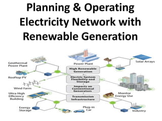
- 1. Planning & Operating Electricity Network with Renewable Generation
- 2. Distributed Generation & Power Quality
- 3. Introduction • Perspectives on DG Benefits – End-User Perspective • Back Generation to Provide Improved Reliability • Reduce Energy Bill • Participation in the Competitive Power Market – Distribution Utility Perspective • Transmission & Distribution Relief • Hedge Against of Uncertain Load Growth • Hedge Against Price Spike – Commercial Power Producer Perspective • Selling Power or Ancillary Service in the Deregulated Market • Integrated Resource Planning
- 4. Introduction • Disadvantages of DG – Power Quality – Cost of Operation and Maintenance – Long Term Reliability of the Units – Interconnection
- 6. DG Technologies • Reciprocating Engine Genset – The Least Expensive DG Technology – High Nox and Sox Emission. This Severely Limits the Number of Hours the Units, Particularly Diesels, May Operate per Year. – Natural Gas-Fire Engine Produce Fewer Emission. However, the Natural Gas Price is Unpredictable.
- 7. DG Technologies • Reciprocating Engine Genset
- 8. DG Technologies • Combustion Turbine – Range from 1 to 10 MW – High Speed: 8 – 12 kRPM – Microturbine • 30 – 75 kW • 10 – 100 kRPM • Efficiency: 25 – 30 %
- 9. DG Technologies • Superconducting Magnetic Energy Storage
- 10. DG Technologies • Carbon Nanotube
- 11. DG Technologies • Fuel Cell
- 12. DG Technologies • Fuel Cell – Phosphoric Acid (PAFC) • PAFCs generate electricity at more than 40% efficiency • Operating temperatures are in the range of 300 to 400 degrees F (150 - 200 degrees C) • Existing PAFCs have outputs up to 200 kW, and 1 MW units have been tested • One of the main advantages to this type of fuel cell is that it can use impure hydrogen as fuel. PAFCs can tolerate a CO concentration of about 1.5 percent, which broadens the choice of fuels they can use. If gasoline is used, the sulfur must be removed. • PAFCs are the most mature fuel cell technology.
- 13. DG Technologies • Fuel Cell – Phosphoric Acid (PAFC) • Disadvantages of PAFCs include: it uses expensive platinum as a catalyst, it generates low current and power comparably to other types of fuel cells, and it generally has a large size and weight.
- 14. DG Technologies • Fuel Cell – Proton Exchange Membrane (PEM) • These cells operate at relatively low temperatures (about 175 degrees F or 80 degrees C), have high power density, can vary their output quickly to meet shifts in power demand, and are suited for applications, -- such as in automobiles -- where quick startup is required. • According to DOE, "they are the primary candidates for light- duty vehicles, for buildings, and potentially for much smaller applications such as replacements for rechargeable batteries. • This type of fuel cell is sensitive to fuel impurities. • Cell outputs generally range from 50 to 250 kW.
- 15. DG Technologies • Fuel Cell – Molten Carbonate (MCFC) • These fuel cells use a liquid solution of lithium, sodium and/or potassium carbonates, soaked in a matrix for an electrolyte. • They promise high fuel-to-electricity efficiencies, about 60% normally or 85% with cogeneration, and operate at about 1,200 degrees F or 650 degrees C. • To date, MCFCs have been operated on hydrogen, carbon monoxide, natural gas, propane, landfill gas, marine diesel, and simulated coal gasification products. • 10 kW to 2 MW MCFCs have been tested on a variety of fuels and are primarily targeted to electric utility applications. • A disadvantage to this, however, is that high temperatures enhance corrosion and the breakdown of cell components.
- 16. DG Technologies • Fuel Cell – Solid Oxide (SOFC) • This type could be used in big, high-power applications including industrial and large-scale central electricity generating stations. • Some developers also see SOFC use in motor vehicles and are developing fuel cell auxiliary power units (APUs) with SOFCs. • A solid oxide system usually uses a hard ceramic material of solid zirconium oxide and a small amount of ytrria, instead of a liquid electrolyte, allowing operating temperatures to reach 1,800 degrees F or 1000 degrees C. • Power generating efficiencies could reach 60% and 85% with cogeneration and cell output is up to 100 kW.
- 17. DG Technologies • Fuel Cell – Alkaline • Long used by NASA on space missions, these cells can achieve power generating efficiencies of up to 70 percent. They were used on the Apollo spacecraft to provide both electricity and drinking water. • Their operating temperature is 150 to 200 degrees C (about 300 to 400 degrees F). • They typically have a cell output from 300 watts to 5 kW.
- 18. DG Technologies • Fuel Cell – Direct Methanol Fuel Cells (DMFC) • These cells are similar to the PEM cells in that they both use a polymer membrane as the electrolyte. However, in the DMFC, the anode catalyst itself draws the hydrogen from the liquid methanol, eliminating the need for a fuel reformer. • Efficiencies of about 40% are expected with this type of fuel cell, which would typically operate at a temperature between 120-190 degrees F or 50 -100 degrees C. • This is a relatively low range, making this fuel cell attractive for tiny to mid-sized applications, to power cellular phones and laptops.
- 19. DG Technologies • Fuel Cell – Regenerative Fuel Cells • Still a very young member of the fuel cell family, regenerative fuel cells would be attractive as a closed-loop form of power generation. • Water is separated into hydrogen and oxygen by a solar- powered electrolyser. The hydrogen and oxygen are fed into the fuel cell which generates electricity, heat and water. The water is then recirculated back to the solar-powered electrolyser and the process begins again. • These types of fuel cells are currently being researched by NASA and others worldwide.
- 20. DG Technologies • Fuel Cell – Zinc-Air Fuel Cells (ZAFC) • In a typical zinc/air fuel cell, there is a gas diffusion electrode (GDE), a zinc anode separated by electrolyte, and some form of mechanical separators. • The GDE is a permeable membrane that allows atmospheric oxygen to pass through. After the oxygen has converted into hydroxyl ions and water, the hydroxyl ions will travel through an electrolyte, and reaches the zinc anode. Here, it reacts with the zinc, and forms zinc oxide. This process creates an electrical potential.
- 21. DG Technologies • Fuel Cell – Protonic Ceramic Fuel Cell (PCFC) • This new type of fuel cell is based on a ceramic electrolyte material that exhibits high protonic conductivity at elevated temperatures. • PCFCs share the thermal and kinetic advantages of high temperature operation at 700 degrees Celsius with molten carbonate and solid oxide fuel cells, while exhibiting all of the intrinsic benefits of proton conduction in polymer electrolyte and phosphoric acid fuel cells (PAFCs). • The high operating temperature is necessary to achieve very high electrical fuel efficiency with hydrocarbon fuels. PCFCs can operate at high temperatures and electrochemically oxidize fossil fuels directly to the anode. This eliminates the intermediate step of producing hydrogen through the costly reforming process. .
- 22. DG Technologies • Wind Generation
- 24. Interface to the Utility System • Synchronous Machine • Asynchronous Machine • Electronic Power Inverters
- 25. Power Quality Issues • Sustained Interruptions • Voltage Regulation • Voltage Ride Through • Harmonics • Voltage Sags • Load Following • Power Variation • Misfiring of Reciprocating Engines
- 26. Power Quality Issues • Voltage Support and Ride Through
- 27. Power Quality Issues • Voltage Support and Ride Through
- 28. Power Quality Issues • Helping on Voltage Sags
- 29. Operating Conflicts • Utility Fault-Clearing Requirements
- 30. Operating Conflicts • Reclosing – DG Must Disconnect Early in the Reclose Interval to Allow Time for the Arc to Dissipate. – Reclosing on DG, Particularly Those System Using Rotating Machine Technologies, Can Cause Damage to the Generator or Prime Mover.
- 32. Operating Conflicts • Interference With Relay – Reduction of Reach
- 33. Operating Conflicts • Interference With Relay – Sympathetic Tripping of Feeder Breaker
- 34. Operating Conflicts • Interference With Relay – Defeat of Fuse Saving
- 35. Operating Conflicts • Voltage Regulation Issues
- 36. Operating Conflicts • Voltage Drops Along the Feeder if the DG is Interrupted (Determine the Max. Capacity of DG)
- 37. Operating Conflicts • Excess DG Can Fool Reverse Power Setting on Line Voltage Regulator
- 38. Operating Conflicts • Varying DG Output can Cause Excess Duty on Utility Voltage Regulation Equipment
- 40. Operating Conflicts • Islanding Main Utility Grid DG
- 42. Operating Conflicts • Shunt Capacitor Interaction (Overvoltage due to capacitor)
- 43. Operating Conflicts • Transformer Connections – Grounded Y-Y Connection • No Phase Shift • Less Concern for Ferroresonance • Allow DG to Feed All Types of Faults on the Utility System • Back Feed of the Triplen Harmonic • Should Insert Ground Impedance to Limit the Current
- 44. Operating Conflicts • Transformer Connections – D-Y Connection
- 45. Operating Conflicts • Transformer Connection – Delta-Delta Connection
- 46. Operating Conflicts • Transformer Connection – Grounded Y-D Connection
- 47. DG on Low-Voltage Distribution Networks • Spot Network Arrangement
- 48. DG on Low-Voltage Distribution Networks • Spot Network Arrangement Underground Network NPR NPR NPR NPR NPR NPR NPR
- 49. DG on Low-Voltage Distribution Networks • Arrangement of Network Protector Relay Source Network Transformer Network Protector Network
- 50. DG on Low-Voltage Distribution Networks • A Microcomputer Based Network Protector Relay
- 51. DG on Low-Voltage Distribution Networks • Operation of A Microcomputer Based Network Protector Relay – Network protector relays are used to monitor and control the power flow of low voltage AC to secondary network systems – The purpose of the network protector is to prevent the system from backfeeding and initiate automatic reclosing when the system returns to normal
- 52. DG on Low-Voltage Distribution Networks • Tripping Characteristics of A Microcomputer Based Network Protector Relay 0 o 90 o 270 o 180 o Tripping Region Non-Tripping Region Non-Tripping Region Tripping Region Network Phase Voltage (Unity PF) Current into Network Current into Network (Lagging PF) (Unity PF) Current out of Network Fault Current Max. Torque
- 53. DG on Low-Voltage Distribution Networks • Reclosing Characteristics of A Microcomputer Based Network Protector Relay 0o 1V 2V 3V 4V 5V 6V 7V 8V Phase Relay Characteristic Master Relay Characteristic Offset Voltage Phase Relay Reclosed Region
- 54. DG on Low-Voltage Distribution Networks • Network Primary Feeder Fault
- 55. DG on Low-Voltage Distribution Networks • Fault Current Contribution From Synchronous Local DG
- 56. DG on Low-Voltage Distribution Networks • Inverter Based DG on a Spot Network (Possible Solution)
- 57. DG on Low-Voltage Distribution Networks • Adjustable Reverse Power Characteristics
- 58. Siting DG • DG to Relieve Feeder Overload
- 59. Siting DG • DG to Increase Feeder Capacity
- 60. Siting DG • DG to Provide Voltage Support & Reconfiguration
- 61. Interconnection of DG • Typical Voltage and Frequency Relay Setting for DG Interconnection for a 60 Hz System
- 62. Interconnection of DG • Simple Interconnection Protection Scheme for Small DG
- 63. Interconnection of DG • Interconnection Scheme for Large Synchronous DG