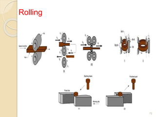
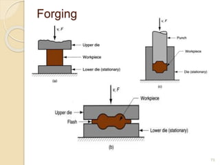
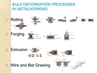
Bulk deformation processes are metal forming operations that cause significant shape change through plastic deformation of initially bulk metal parts like bars, billets, and slabs. The main bulk deformation processes are rolling, forging, extrusion, and drawing.
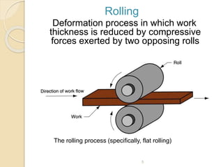
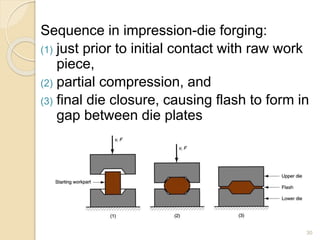
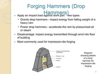
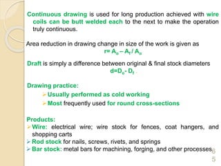
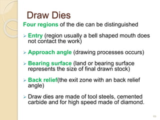
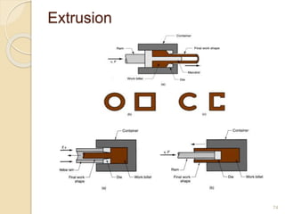
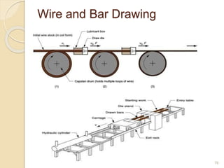
Rolling reduces the thickness of metal by passing it through opposing rolls. Forging shapes metal by compressing it between dies under impact or gradual pressure. Extrusion forces metal through a die opening to take on its cross-sectional shape. Drawing reduces the diameter of wires or bars by pulling them through a die. These processes are commonly done hot to facilitate greater plastic deformation.