1. TSCN notes IT5
Prepared by: Minu Choudhary, (RCET, Bhilai) Page 1
Syllabus
Basic concept of telephony system & topology,
Multiplexing,
Circuit / Packet switching,
PSTN,
ISDN,
DSL,
ADSL,
Framing,
Cable technology
Addressing/Routing
BASIC CONCEPT OF TELEPHONY SYSTEM AND TOPOLOGY
A telephone system is a system that connects telephones together. Its main function is to provide
voice conversation service to the users. To properly perform this function, switching is required.
Nowadays telephone systems use a hierarchical switching structure.
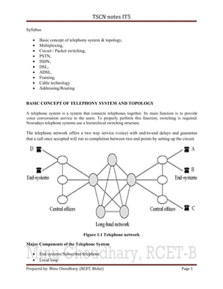
The telephone network offers a two way service (voice) with end-to-end delays and guarantee
that a call once accepted will run to completion between two end points by setting up the circuit.
Figure 1.1 Telephone network
Major Components of the Telephone System
End systems/Subscriber/telephone
Local loop
2. TSCN notes IT5
Prepared by: Minu Choudhary, (RCET, Bhilai) Page 2
Central office/local exchange/end office (switching facilities)
Toll offices/ backbone switch/ intertoll office trunk (trunk circuits)
End system directly connected with the switches of end office also called local loops/exchange.
It consists of twisted pairs now-a-days. The distance is typically 1 to 10 km. The end office
provides power for operation of the end system. It receives dial digits and place call on behalf of
the end system. It receives dial digits and places call on behalf of the end system.
Parts of end system
Transducers
o Voice-to-electrical signal transducer
o An electrical signal to voice transducer
Dialer: sends a series of pulses to a central office
Ringer
Switch hook
Local loop: The link that connects a home telephone to a telephone office. The local loop is the
pair of wires that go from a telephone office to each home. Figure 1.2 shows how these wires go
from a telephone office (called a central office) to an area that the office is serving. Figure 1.3
shows a telephone box which connects to one end of a local loop. A cable from a telephone
instrument can be plugged into the socket on the box for connection to the telephone system.
Figure 1.2 Local loop
3. TSCN notes IT5
Prepared by: Minu Choudhary, (RCET, Bhilai) Page 3
Figure 1.3 The local loop
Figure 1.4 A telephone box.
Central Office: A lower level telephone office that connects to user telephones. Central office
further connected to long haul or backbone switches. It is almost full connected, that is every
switch or backbone is one hop away from the other switch. The number of backbone switches is
less compared to local exchanges. When exchange receives a call and if end system is attached to
the same exchange it creates a local path from source to destination system. If call is not local, it
forwards the call either to another exchange in the local area or to the nearest switch in the
backbone network. This switch in turn connects another switch nearest to the destination
exchange. Backbone switches choosing this path easy. In some networks if single hop path is
congested, the call is diverted to an alternate two hop path.
Telephone Switch: A device that connects multiple telephone lines together and provides
communication paths for the lines.
4. TSCN notes IT5
Prepared by: Minu Choudhary, (RCET, Bhilai) Page 4
Trunk Circuits: The communication circuits between two switching offices.
Switching: The setting up and releasing of connections between two telephones when needed.
Hierarchical Switching: The switching approach that organizes the switches in a hierarchical (tree-
like) structure.
A special purpose computer called a switching system interprets them to place a call or activate
special features such as call forwarding. Switching system sends a ring signal to the instrument
when call arrives. The central office supplies the power for ringing the bell.
Why switching is needed?
If there are only two or three telephones, calls can be made between any two of them if they have
direct wires connecting them. In this case, no switching is required. However, if the number of
telephones increases, the number of wires connecting the telephones will also need to increase at
a very fast pace. Since it is not possible to install so many wires in practice, switching is required.
The concept on switching is simple – setting up and releasing connections between two
telephones when needed. However, there are over 600 million telephones in the world. Switching
for so many telephones is not an easy task. In a telephone system, switching is carried out by
telephone offices. The telephone offices are connected together by trunk circuits in a hierarchical
structure as shown in Figure 5.3.2. In the figure, there are two levels of telephone offices. The
squares are the higher level ones called toll offices. Each of these telephone offices serves a large
geographical area. All the lower level telephone offices in an area, called local central offices (or
simply central offices), will be connected to the toll office of the area via the trunk circuits. With
the help of the local loops, telephones are in turn connected to the nearest local central offices.
Figure 1.5 Switching is required if there are many telephones to be connected together
5. TSCN notes IT5
Prepared by: Minu Choudhary, (RCET, Bhilai) Page 5
Figure 1.6 Hierarchical switching used in telephone systems
Toll offices: A higher level telephone office that usually provides long-distance connections.
Structure/topology of the Telephone System
Figure 1.7 (a) Fully-interconnected network. (b) Centralized switch. (c) Two-level
hierarchy.
Fully-interconnected network: if a telephone owner wanted to talk to n other telephone owners,
separate wires had to be strung to all n houses. It became immediately obvious that the model of
connecting every telephone to every other telephone was not going to work.
Centralized switch: the company ran a wire to each customer’s house or office. To make a call,
the customer would crank the phone to make a ringing sound in the telephone company office to
attract the attention of an operator, who would then manually connect the caller to the callee
using a jumper cable.
6. TSCN notes IT5
Prepared by: Minu Choudhary, (RCET, Bhilai) Page 6
Two-level hierarchy: the original problem soon returned; to connect every switching office to
every other switching office by means of a wire between them quickly became unmanageable, so
second-level switching offices were invented. After a while, multiple second-level offices were
needed. A telephone network consisting only of telephones (the small dots), end offices (the
large dots) and toll offices (the squares).
Figure 1.8 A typical circuit route for a medium-distance call
MULTIPLEXING
It is the set of techniques that allows the simultaneous transmission of multiple signals across a
single link. In a multiplexed system, n devices share the capacity of one link. It is also known as
muxing. A device that performs the multiplexing is called a multiplexer (MUX). A device that
performs the demultiplexing is called a demultiplexer (DEMUX).
The word path refers to the physical link. The word channel refers to a portion of a path that
carries a transmission between a given pair of devices. One path can have many (n) channels.
Figure 1.9 Multiplexing vs. No Multiplexing
7. TSCN notes IT5
Prepared by: Minu Choudhary, (RCET, Bhilai) Page 7
Signals are multiplexed using three basic techniques:
Frequency-division multiplexing (FDM)
Time-division multiplexing (TDM)
Wave-division multiplexing (WDM)
Figure 1.10 Types of Multiplexing
FDM
Frequency-division multiplexing (FDM) is a scheme in which numerous signals are combined
for transmission on a single communications line or channel. Each signal is assigned a different
frequency (sub channel) within the main channel. Example: television broad casting.
Figure 1.11 FDM
In the figure 1.11, the transmission path is divided into three parts, each representing a channel to
carry one transmission. As an analogy, imagine a point where three narrow streets merge to form
a three-lane highway. Each of three streets corresponds to a lane of the highway. Each car
merging onto the highway from one of the streets still has its own lane and can travel without
interfering with cars in other lanes. The path as divided spatially into separate channels. Actual
channel divisions are achieved by frequency rather than by space.
8. TSCN notes IT5
Prepared by: Minu Choudhary, (RCET, Bhilai) Page 8
Figure 1.12 FDM Multiplexing Process
FDM is an analog process and we show it here using telephones as the input and output devices.
Each telephone generates a signal of a similar frequency range. Inside the multiplexer, these
similar signals are modulated onto different carrier frequencies (f1, f2, and f3). The resulting
modulated signals are then combined into a signal composite signal that is sent out over a media
link that has enough bandwidth to accommodate it.
Figure 1.13 Demultiplexing Process
The demultiplexer uses a series of filters to decompose the multiplexed signal into its constituent
component signals. The individual signals are then passed to a demodulator that separates them
from their carriers and passes them to the waiting receivers.
Advantages of FDM
• It is not sensitive to propagation delays.
9. TSCN notes IT5
Prepared by: Minu Choudhary, (RCET, Bhilai) Page 9
• It allows maximum transmission link usage.
Disadvantages of FDM
• There is the need for filters, which are relatively expensive and complicated to construct
and design.
• Sometimes, it is necessary to use more complex linear amplifiers in FDM systems.
Time division multiplexing (TDM)
A type of multiplexing where two or more channels of information are transmitted over the same
link by allocating a different time interval (“slot” or “slice”) for the transmission of each channel,
i.e., the channels take turns to use the link. Example: telephone system
Figure 1.14 Time division multiplexing (TDM)
Figure 1.14 gives a conceptual view of TDM. In this, portions of signals 1, 2, 3, and 4 occupy the
link sequentially. TDM can be implemented in two ways:
– Synchronous TDM
– Asynchronous TDM
Synchronous TDM
In this the multiplexer allocates exactly the same time slot to each device at all times, whether or
not a device has anything to transmit. Time slot A, for example, is assigned to device A alone
and cannot be used by any other device. Each time its allocated time slot comes up, a device has
the opportunity to send a portion of its data. If a device is unable to transmit or does not have
data to send, its time slot remains empty.
10. TSCN notes IT5
Prepared by: Minu Choudhary, (RCET, Bhilai) Page 10
Figure 1.15 Synchronous TDM
Frames
Time slots are grouped into frames. A frame consists of one complete cycle of time slots. In a
system with n input lines, each frame has at least n slots. In the above figure, there are 5 input
lines multiplexed onto a single path using synchronous TDM. In this example, all of the inputs
have the same data rate, so the number of time slots in each frame is equal to the number of input
lines.
Figure 1.16 Synchronous TDM Multiplexing
11. TSCN notes IT5
Prepared by: Minu Choudhary, (RCET, Bhilai) Page 11
Figure 1.17 Synchronous TDM Demultiplexing
In both the figure 1.16 & 1.17, only the first three frames are completely filled. The last three
frames have a collective six empty slots. Here 6 empty slots out of 24 means that a quarter of the
capacity of the link is being wasted.
Asynchronous TDM
It allows a number of lower-speed input lines to be multiplexed to a single higher-speed line. If
we have n input lines, the frame contains no more than m slots, with m less than n. in this way,
asynchronous TDM supports the same number of input lines as synchronous TDM with a lower
capacity link. Or, given the same link, asynchronous TDM can support more devices than
synchronous TDM. The number of time slots in an asynchronous TDM frame (m) is based o a
statistical analysis of the input lines that are likely to be transmitted at any given time.
Figure 1.18 Asynchronous TDM
12. TSCN notes IT5
Prepared by: Minu Choudhary, (RCET, Bhilai) Page 12
Figure 1.19 Examples of asynchronous TDM frames
Figure 1.19 shows a system where five computers are sharing a data link using asynchronous
TDM. In this example, the frame size is three slots. The figure shows how the multiplexer
handles three levels of traffic. In the first case, only three of the five computers have data to send.
In second case, four lines are sending data, one more than the number of slots per frame. In the
third case, all lines are sending data. In each case, the multiplexer scans the devices in order,
from 1 to 5, filling time slots as it encounters data to be sent.
Case 1: In the first case, the three active input lines correspond to the three slots in each frame.
For the first four frames, the input is symmetrically distributed among all the communicating
devices. By the fifth frame, devices 3 and 5 have completed their transmissions, but device 1 still
has two characters to go. The multiplexer picks up the A from device 1, scans down the line
without finding another transmission, and returns to device 1 to pick up the last A. there being no
data to fill the final slot, the multiplier then transmits the fifth frame with only two slots filled.
13. TSCN notes IT5
Prepared by: Minu Choudhary, (RCET, Bhilai) Page 13
Case 2: In this case, there is one more active input line than there are slots in each frame. This
time as the multiplexer scans from 1 to 5, it fills up a frame before all of the lines have been
checked. The first frame carries data from devices 1, 3, and 4, but not 5. The multiplexer
continues its scan where it left off, putting the first portion of device 5’s transmission into the
first slot of the next frame, then moving back to the top of the line and putting the second portion
of device 1’s data into the second slot and so on.
Case 3: In the 3rd
case, the frames are filled as above, but here all five input lines are active. In
this example, device 1 occupies the first slot in the first frame, the third slot in the second frame,
and no slot at all in the third frame.
Advantages of TDM
It uses relatively simple and less costly digital logic circuits.
Disadvantages of TDM
• It is sensitive to propagation delays.
• It operates with low network efficiency.
• Capacity of the link is wasted.
Wave division multiplexing (WDM)
It is conceptually the same as FDM, except that it involves light signals transmitted through fiber
optic channel. Multiplexer combine multiple light sources into one single light and do the reverse
at the demultiplexer. Example: optical networking
Advantages of WDM
• WDM is fast.
Disadvantages of WDM
• WDM systems were expensive and complicated to run.
Table 1.1 Differentiate between TDM and FDM
14. TSCN notes IT5
Prepared by: Minu Choudhary, (RCET, Bhilai) Page 14
SWITCHING
Why Switching?
Whenever we have multiple devices, we have the problem of how to connect them to make one-
on-one communication possible. One solution is to install a mesh or star topology. However
these methods are impractical and wasteful when applied to very large networks. The number
and length of the links require too much infrastructure to be cost efficient, and the majority of
those links would be idle most of the time. A better solution is switching.
What is switching?
The process of interconnecting multiple nodes in a network is called switching. A switched
network consists of a series of interlinked nodes, called switches. Switches are hardware and /or
software devices capable of creating temporary connections between two or more devices.
Figure 1.20 shows a switched network. The communicating devices are labeled A, B, C, and D
and so on, and the switches I, II, III, IV, and so on. Each switch is connected to multiple links
and is used to complete the connections between them.
15. TSCN notes IT5
Prepared by: Minu Choudhary, (RCET, Bhilai) Page 15
Figure 1.20 Switched network
Figure 1.21 Switching methods
Circuit-switched Network
Circuit switching creates a direct physical connection between two devices such as phones or
computers. In the figure 1.22, instead of point-to-point connections between the three computers
on the left to the four computers on the right, requiring 12 links, we can use four switches to
reduce the number and the total length of the links. By moving the levers of the switches, any
computer on the left can be connected to any computer on the right.
Figure 1.22 Circuit-switched Network
16. TSCN notes IT5
Prepared by: Minu Choudhary, (RCET, Bhilai) Page 16
A circuit switch
A circuit switch is a device with n inputs and m outputs that create a temporary connection
between an input link and an output link (see figure 1.23). The number of inputs does not have to
match the number of outputs.
Figure 1.23 Switch
Folded Switch
An n-by-n folded switch can connect n lines in full-duplex mode. For example, it can connect n
telephones in such a way that each phone can be connected to every other phone (see figure1.24).
Figure 1.24 Folded switch
Figure 1.25 Circuit switching
Space-Division Switches
In this, the paths in the circuit are separated from each other spatially. A type of switching
system in which all of the links, contacts, matrix cross points, and switches are physically
separated. This technology was originally designed for use in analog networks but is used
currently in both analog and digital networks.
17. TSCN notes IT5
Prepared by: Minu Choudhary, (RCET, Bhilai) Page 17
Crossbar Switch
A crossbar switch connects n inputs to m outputs in a grid, using electronic micro-switches
(transistors) at each cross point (see figure 1.26). The major limitation of this design is the
number of cross points required. Connecting n inputs to m outputs using a crossbar switch
requires n x m cross points. For example, to connect 1000 inputs to 1000 outputs requires a
crossbar with 1,000,000 cross points. This factor makes the crossbar impractical because it
makes the size of the crossbar huge
Figure 1.26 Crossbar Switch
Multistage Switch
The solution to the limitations of the crossbar switch is to use multistage switches, which
combine crossbar switches in several stages. In multistage switching, devices are linked to
switches that, in turn, are linked to a hierarchy of other switches.
Figure 1.27 Multistage switch
18. TSCN notes IT5
Prepared by: Minu Choudhary, (RCET, Bhilai) Page 18
The design of a multistage switch depends on the number of stages and the number of switches
required in each stage. Normally, the middle stages have fewer switches than do the first and last
stages. For example, imagine that we want a multistage switch as in figure 1.27 to do the job of a
single 15-by-15 crossbar switch.
Assume that we have decided on a three-stage design that uses three switches in the first and
final stages and two switches in the middle stage. Because there are three of them, each of the
first stage switches has inputs from one third of the input devices, giving them five inputs each (5
X 3=15).
Next, each of the first-stage switches must have an output to each of the intermediate switches.
There are two intermediate switches; therefore, each first-stage switch has two outputs. Each
third-stage switch must have inputs from each of the intermediate switches; two intermediate
switches mean two inputs. The intermediate switches must connect to all three first-stage
switches and all three last stage switches, and so must have three inputs and three outputs each.
Multiple Paths
Multistage switches provide several options for connecting each pair of linked devices. Figure
1.28 shows two ways traffic can move from an input to an output using the switch designed in
the example above.
In figure 1.28 a, a pathway is established between input line 4 and output line 9. In this instance,
the path uses the lower intermediate switch and that switch’s center output line to reach the last-
stage switch connected to line 9.
Figure 1.28 b, shows a pathway between the input line 13 and output line2.
(a) (b)
Figure 1.28 Switching Path
19. TSCN notes IT5
Prepared by: Minu Choudhary, (RCET, Bhilai) Page 19
Time-Division Switches
It uses time-division multiplexing to achieve switching. There are two popular methods used in
time-division multiplexing:
– Time-slot interchange (TSI)
– TDM bus
Figure 1.29 Time-division multiplexing, without and with a time-slot interchange
Time-slot interchange (TSI)
Figure 1.28 shows a system connecting four input lines to four output lines. If input line wants to
send data to an output line according to the following pattern:
1-3 2-4 3-1 4-2
In figure 1.29 a, the desired task is not accomplished. Data are output in the same order as they
are input. In figure 1.29 b, we insert a device TSI into the link. A TSI changes the order of the
slots based on the desired connections. In this case, it changes the order of data from A, B, C, D
to C, D, A, B. now, when the demultiplexer separates the slots, it passes them to the proper
outputs.
20. TSCN notes IT5
Prepared by: Minu Choudhary, (RCET, Bhilai) Page 20
Figure 1.30 Time-slot interchange
How a TSI works is shown in figure 1.30. TSI consists of random access memory (RAM) with
several memory locations. The size of each location is the same as the size of a single slot. The
number of locations is the same as the number of inputs. The RAM fills up with incoming data
from time slots in the order received. Slots are then sent out in an order based on the decisions of
a control unit.
TDM bus
Figure 1.31 shows a very simplified version of a TDM bus. The input and output lines are
connected to a high speed bus through input and output gates (microswitches). Each input gate is
closed during one of the four time slots. During the same time slot, only one output gate is also
closed. This pair of gates allows a burst of data to be transferred from one specific input line to
one specific output line using the bus. The control unit opens and closes the gates according to
switching need. For example, in the figure, at the first time slot the input gate 1 and output gate 3
will be closed; during the second time slot, input gate 2 and output gate 4 will be closed; and so
on.
Figure 1.31 TDM bus
21. TSCN notes IT5
Prepared by: Minu Choudhary, (RCET, Bhilai) Page 21
Circuit switching Advantages
• Designed for voice communication
Circuit switching disadvantages
• It is less well suited to data and other non-voice transmission.
• It is inflexible.
• Data rate is low.
Packet switching
In packet switching there are no dedicated circuits. In this, each message are broken up into
packets, each of which includes a header with source, destination and intermediate node address
information. Individual packets take different routes to reach the destination. In this, the packet
length is restricted to a maximum length. This length is short enough to allow the switching
devices to store the packet data in memory without writing any of it to disk.
Figure 1.32 Packet switching types
Datagram approach
In this method a message is divided into a stream of packets. Each packet is separately addressed
and treated as an independent unit with its own control instructors. The switching devices route
each packet independently through the packet’s next route segment. Before transmission starts,
the sequence of packets and their destinations are established by the exchange of control
information between the sending terminal, the network and the receiving terminal.
22. TSCN notes IT5
Prepared by: Minu Choudhary, (RCET, Bhilai) Page 22
Figure 1.33 Datagram approach
Figure 1.33 shows how the datagram approach can be used to deliver four packets from station A
to station X. In this example, all four packets belong to the same message but may go by
different paths to reach their destination. This approach can cause the datagram of a transmission
to arrive at their destination out of order. It is the responsibility of the transport layer in most
protocols to reorder the datagram before passing them on to the destination port.
Virtual Circuit Approach
In this approach, the relationship between all packets belonging to a message or session is
preserved. A single route is chosen between sender and receiver at the beginning of the session.
When the data are sent, all packets of the transmission travel one after another along that route.
Virtual circuit transmission is implemented in two formats:
– Switched virtual circuit (SVC)
– Permanent virtual circuit (PVC)
Switched virtual circuit (SVC)
In this method, a virtual circuit is created whenever it is needed and exists only for the duration
of the specific exchange.
23. TSCN notes IT5
Prepared by: Minu Choudhary, (RCET, Bhilai) Page 23
Connection establishment Data transfer
Connection release
Figure 1.34 Switched Virtual Circuit (SVC)
For example, imagine that station A wants to send four packets to station X. First, A requests the
establishment of a connection to X. once the connection is in place, the packets are sent one after
another and in sequential order. When the last packet has been received and, if necessary,
acknowledged, the connection is released and that virtual circuit ceases to exist (see figure 1.34).
Only one single route exists for the duration of transmission, although the network could pick an
alternate route in response to failure or congestion. Each time that A wishes to communicate with
X, a new route is established. The route may be same each time, or it may differ in response to
varying network conditions.
Permanent virtual circuit (PVC)
In this method, the same virtual circuit is provided between two users on a continuous basis. The
circuit is dedicated to the specific users. No one else can use it and, because it is always in place,
it can be used without connection establishment and connection termination. Whereas two SVC
users may get a different route every time they request a connection, two PVC users always get
the same route.
Figure 1.35 PVC
Message switching
It is best known by the descriptive team store and forward. In this method, a node receives a
message, stores it until the appropriate route is free, then sends it along. Store and forward is
24. TSCN notes IT5
Prepared by: Minu Choudhary, (RCET, Bhilai) Page 24
considered a switching technique because there is no direct link between the sender and receiver
of a transmission. A message is delivered to the node along one path then routed along another to
its destination.
Figure 1.36 Message Switching
Table 1.2 Difference between message, circuit and packet switching
25. TSCN notes IT5
Prepared by: Minu Choudhary, (RCET, Bhilai) Page 25
PSTN
PSTN is the telephone network that by default most of the world population is connected to if
they have a telephone. For a long time, the PSTN was the only bearer network available for
telephony. Other bearer networks for voice transmission include integrated service digital
network (ISDN), ATM, frame relay.
PSTN characteristics
• Analog access
• Circuit switched duplex connection
• Immobility
• Switched bandwidth, 64kbits/s
Understanding PSTN basics
(i) Analog and digital signaling: everything you hear, including human speech, is in
analog form. Although analog communication is ideal for human interaction, it is
neither robust nor efficient at recovering from noise. In the early telephony network,
analog transmission was passed through amplifiers to boost the signal. But, this
practice amplified not just the voice, but the noise as well. If you were far away from
the end office switch, an amplifier might be required to boost the analog transmission.
In digital networks, noise is less of an issue because repeaters not only amplify the
signal, but also clean it to its original condition. This is possible with digital
communication because such communication is based on 1’s and 0’s. Therefore,
when signals are repeated, a clean sound is maintained. When the benefits of this
digital representation became evident, the telephony network migrated to Pulse Code
Modulation (PCM).
PCM is the most common method of encoding an analog voice signal into a digital
stream of 1’s and 0’s.
(ii) Local Loops, Trunks, and Inter-switch Communication: the telephone
infrastructure starts with a simple pair of copper wires running to your home. This
physical cabling is known as a local loop. The local loop physically connects your
home telephone to the central office switch (also known as class 5 switches or end
office switch). The communication path between the central office switch and your
home is known as the phone line, and it normally runs over the local loop. The
communication path between several central office switches is known as a trunk.
Switches are currently deployed in hierarchies. End office switches interconnect
through trunks to tandem switches (also referred to as class 4 switches). Central office
switches often directly connect to each other. The direct connections that occur
between central office switches depend to a great extent on call patterns. PSTN use
as many as five levels of switching hierarchy.
26. TSCN notes IT5
Prepared by: Minu Choudhary, (RCET, Bhilai) Page 26
Figure 1.37 PSTN hierarchy
(iii) PSTN signaling: generally, two types of signaling methods run over various
transmission media. The signaling methods are broken into the following groups:
User-to-network signaling: The most common signaling method for user-to-network
analog communication is Dual Tone Multi Frequency (DTMF). When you pick up
your phone handset and press the digits the tone that passes from your phone to the
central office switch to which you are connected tells the switch what number you
want to call.
Network-to-network signaling: it uses an out-of –bound signaling method known as
Signaling System 7(SS7). SS7 is beneficial because it interconnects to the Intelligent
Network (IN). Connection to the IN enables the PSTN to offer Custom Local Area
Signaling Services (CLASS). These CLASS services still rely on the end-offices
switches and the SS7 network.
(iv) PSTN services: the following list shows just few of the services that you may have
on offer from your operator.
Calling line identification presentation (CLIP): also called “caller ID”, this service
allows a called party to see the telephone number of an incoming call on a display
27. TSCN notes IT5
Prepared by: Minu Choudhary, (RCET, Bhilai) Page 27
connected to the telephone line. There are two commonly accepted ways of
transmitting the CLIP information-via DTMF or phase-Shift Key (PSK) signaling.
Call forwarding: this service re-routes incoming calls to another number.
Call-back: if the called subscriber is busy, the caller can order the call back service,
which means that he is queued for connection to the busy number and when that
subscriber gets the network will connect and notify the caller.
Call waiting: a special signal is generated during a call in progress to indicate that a
third party is trying to reach you.
(v) Drawbacks to the PSTN: although the PSTN is effective and does a good job at
what it was built to do, many business drivers are striving to change it to a new
network. This is happening for several reasons:
Data has overtaken voice as the primary traffic on many networks built for
voice. Data is now running on top of networks that were built to carry
voice efficiently.
The PSTN cannot create and deploy features quickly enough.
Data/voice/video cannot converge on the PSTN as currently built.
The architecture built for voice is not flexible enough to carry data.
ISDN (Integrated Services Digital Network)
ISDN was developed by ITU-T in 1976. It is a set of protocols that combines digital telephony
and data transport services. The whole idea is to digitize the telephone network to permit the
transmission of audio, video, and text over existing telephone lines.
ISDN is an effort to standardize subscriber services, provide user/network interfaces, and
facilitate the internetworking capabilities of existing voice and data networks.
The goal of ISDN is to form a wide area network that provides universal end-to-end connectivity
over digital media. This can be done integrating all of the separate transmission services into one
without adding new links or subscriber lines.
ISDN Services
The purpose of the ISDN is to provide fully integrated digital services to users. These services
fall into three categories:
Bearer services: it provides the means to transfer information (voice, data, and video) between
users without the network manipulating the content of that information. The network does not
need to process the information and therefore does not change the content. Bearer services
belong to the first three layers of the OSI model and are well defined in the ISDN standard. They
28. TSCN notes IT5
Prepared by: Minu Choudhary, (RCET, Bhilai) Page 28
can be provided using circuit-switched, packet-switched, frame-switched, or cell-switched
networks.
Teleservices: in Teleservices, the network may change or process the content of data. These
services correspond to layers 4-7 of the OSI model. Teleservices rely on the facilities of the
bearer services and are designed to accommodate complex user needs without the user having to
be aware of the details of the process. Teleservices include telephony, teletex, telefax, videotex,
telex, and teleconferencing.
Supplementary services: these are those services that provide additional functionality to the
bearer services and Teleservices. Examples of these services are reverse charging, call waiting,
and message handling.
Figure 1.38 ISDN services
History
The evolution of the ISDN reveals the concepts most critical to an understanding of it.
Voice Communication over an Analog Telephone Network
Initially, telecommunications networks were entirely analog networks and were used for the
transmission of analog information in the form of voice. The local loops connecting the
subscriber’s handset to the telephone company’s central office were also analog (see figure 1.39).
Figure 1.39 Voice Communication over an Analog Telephone Network
Voice and Data Communication over an Analog Telephone Network
29. TSCN notes IT5
Prepared by: Minu Choudhary, (RCET, Bhilai) Page 29
With the advent of digital processing, subscribers needed to exchange data as well as voice.
Modems were developed to allow digital exchanges over existing analog lines (see figure 1.40).
Figure 1.40 Voice and Data Communication over an Analog Telephone Network
Analog and Digital Services to Subscribers
To reduce cost and improve performance, the telephone companies gradually began to add
digital technologies while continuing their analog services to their customers (see figure 1.41).
Three types of customers were identified at this time: traditional customers using their local
loops only for analog purposes; customers using analog facilities to transmit digital information
via modem; and customers using digital services to transmit digital information. Of these, the
first group was still the most prominent and therefore most of the services offered remained
analog.
Figure 1.41 Analog and Digital Services over the Telephone Network
Integrated Digital Network (IDN)
Next, customers began to require access to a variety of networks, such as packet-switched
networks and circuit-switched networks. To meet these needs, the telephone companies created
Integrated Digital Networks (IDNs). An IDN is a combination of networks available for different
30. TSCN notes IT5
Prepared by: Minu Choudhary, (RCET, Bhilai) Page 30
purposes (see figure 1.42). Access to these networks is by digital pipes, which are time-
multiplexed channels sharing very-high-speed paths. Customers can use their local loops to
transmit both voice and data to their telephone company’s central office. The office then redirect
these calls to the appropriate digital networks via the digital pipes.
Figure 1.42 IDN
Integrated Services Digital Network (ISDN)
The ISDN integrates customer services with the IDN. To receive the maximum benefit from the
integrated digital networks, the next step is to replace the analog local loops with digital
subscriber loops. Voice transmissions can be digitized at the source, thereby removing the final
need for analog carriers. It then becomes possible to send data, voice, image, facsimile, and so on
over any digital network. With ISDN all customer services will become digital rather than analog,
and the flexibility offered by the new technology will allow customer services to be made
available on demand. Most important, ISDN will allow all communication connections in a
home or building to occur via a single interface.
Figure 1.43 gives a conceptual view of the connections between users and an ISDN central office.
Each user is linked to the central office through a digital pipe. These pipes can be of different
capacities to allow different rates of transmission and support different subscriber needs.
31. TSCN notes IT5
Prepared by: Minu Choudhary, (RCET, Bhilai) Page 31
Figure 1.43 ISDN
ISDN channel types
Information is transferred between a user and the Central Office (or ISDN station) via channels.
A channel is defined as a specific portion of the total digital bandwidth of the transmission line.
ISDN standards define
Bearer channel (B channel)
Data channel (D channel)
Hybrid channels (H channels)
Bearer channel (B channel)
The B, or bearer channel, is a 64 kbps digital channel. It does not carry signaling (control)
information. Digitized voice or data transmissions (including video) in either circuit-switched or
packet-switched formats can be transported, however. Older, standard data terminals may be
adapted to the B channel through well-defined rate adaption algorithms (like V.110 and V.120).
B channels also may be combined to achieve greater aggregate speeds. Multilink Point-to-Point
Protocol (MLPPP) or Bandwidth on Demand (BONDing) are two major methods for achieving
higher aggregate speeds. For example, the two 64 kbps B channels of a BRI may be combined to
achieve 128 kbps aggregate data speed.
Data channel (D channel)
The D, demand or data channel, is a separate 16 or 64 kbps channel used primarily for signaling
information. Signaling information establishes, maintains, and clears ISDN network connections.
32. TSCN notes IT5
Prepared by: Minu Choudhary, (RCET, Bhilai) Page 32
The nature of the signaling functions cause signaling to occur in bursts. When the D channel is
not carrying signaling information, provisions have been made to allow packet-switched (X.25)
data to be transmitted. Signaling information, however, has priority on the D channel at all times.
Hybrid channels (H channels)
The H channel has been designed for high-bandwidth applications and bonds multiple B
channels. H channels provide greater aggregate bandwidth in PRI applications. This capability of
channel aggregation allows multi-rate communications on a dynamic basis through inverse
multiplexing over multiple B channels. Table 1.3 summarizes the functions of the B, D, and H
channels.
Table 1.3 Functions of the channels
User interfaces
Digital subscriber loops are of two types:
Basic Rate Interface (BRI). The Basic Rate Interface (BRI) consists of two B channels and one
D channel. This configuration is often called 2B + D. The two B channels may be independently
accessed. For example, one B channel can carry voice information while the other B channel is
carrying data. In this manner, voice and data can be integrated over the same transmission
facilities. The D channel carries the signaling information controlling the two B channels, as well
as being used to transfer packet-switched data, like X.25, in the extra bandwidth. A single BRI
can support up to eight devices (telephones, fax machines, PCs, modems, etc.). While BRI
supports as many as three simultaneous calls, only one can be a voice conversation. BRI
typically is implemented using an 8-pin RJ-45 connector. Full-duplex connectivity is
accomplished over a twisted-pair local loop through the application of special carrier electronics.
Figure 1.44 BRI
33. TSCN notes IT5
Prepared by: Minu Choudhary, (RCET, Bhilai) Page 33
Primary Rate Interface (PRI). There are two versions of Primary Rate Interface (PRI). In
North America and several other locations in the world, the primary rate interface consists of 23
B channels, a D channel, and overhead. The second version, used in Europe and throughout the
rest of the world, consists of 30 B channels, a D channel, and overhead. The standards specify
that a D channel can support up to five PRI connections. PRI provides a full-duplex point-to-
point connection.
Figure 1.45 PRI
ISDN Architecture and Operation
This section will describe the types of ISDN equipment and how the equipment is interconnected
to create ISDN networks. On the user’s premise there are two types of functional blocks:
■ Network Termination Equipment (NT)
■ Terminal Equipment (TE)
Functional blocks are logical representations that perform specific functions. Functional blocks
may be combined when designing real equipment. Depending on the user’s needs and network
configuration, some functional blocks might not be necessary. The interfaces between functional
blocks are called reference points. Reference points also are logical rather than physical; there
might not be a physical interface at a given reference point. This is the case when the functions
of one piece of equipment are provided in another piece of equipment. By interconnecting
functional blocks and reference points, ISDN networks can be constructed.
Network Termination (NT) Equipment: Network Termination (NT) equipment handles
communication between the ISDN exchange and the customer premises. NT equipment typically
is the demarcation point (“demarc”) between the customer premises and the network
administration. There are two types of NT equipment, NT1 and NT2. NT1 devices provide
functions equivalent to the Physical layer (layer 1) of the OSI model. These functions include
signal conversion, timing, maintenance of the physical transmission line, and the physical and
electrical termination of the network at the user end. Sometimes the NT1 is built into another
piece of equipment and therefore might not exist physically as a separate device. The
functionality of the NT1 must be present in an ISDN network, however.
34. TSCN notes IT5
Prepared by: Minu Choudhary, (RCET, Bhilai) Page 34
NT2 devices are more intelligent than NT1 devices. NT2 devices perform Data Link layer (layer
2) as well as Network layer (layer 3) functions. Whenever the NT2 does not provide layer 3
capabilities, then the NT2 will pass the original layer 2 and layer 3 data received from NT1 to the
Terminal Equipment. NT2 equipment provides local premises distribution functions, like
controlling multiple BRIs feeding into a single PRI. NT2 examples include PBXs, concentrators,
terminal controllers, frontend processors, and T1 multiplexers.
Terminal Equipment (TE): Terminal equipment handles communication on the customer
premises. Examples of terminal equipment include data terminals, telephones, personal
computers, and digital telephones. TE devices provide protocol handling, maintenance functions,
interface functions, and connection functions to other equipment. Terminal Equipment type 1
(TE1) devices perform the functions listed above, as well as containing an interface that is
compatible with the ISDN network interface recommendations. Examples of TE1s include
voice/data terminals, digital telephones, and computers with ISDN cards and software. Terminal
Equipment type 2 (TE2) devices also perform the TE function as listed above, except for the
signaling protocol. TE2s do not contain an ISDN-compatible interface.
Instead, they have a non-ISDN-compatible interface, such as RS-232, V.35, or X.21. TE2s must
be connected to ISDN through a Terminal Adapter (TA). Today’s standard personal computers
and telephones are examples of TE2s.
Terminal Adapters (TA) allow TE2 devices to interface to an ISDN network. TAs performs such
functions as converting non-ISDN transmission rates and protocols to ISDN standards. TAs also
provides the D channel signaling. TAs may be separate devices, or they may be integrated into
an NT2 or a TE2.
Figure 1.46 Functional grouping
Reference Points
Reference point refers to the label used to identify individual interfaces between two elements of
an ISDN installation. A reference point defines the functions of the connections between them. A
reference point defines how two network elements must be connected and the format of the
traffic between them.
35. TSCN notes IT5
Prepared by: Minu Choudhary, (RCET, Bhilai) Page 35
Reference point R defines the connection between a TE2 and a TA. Reference point S defines
the connection between a TE1 or TA and an NT1 or NT2.
Reference point T defines the interface between an NT2 and an NT1. Finally, reference point U
defines the interface between an NT1 and ISDN office.
Figure 1.47 Reference points
The ISDN layers
It is difficult to apply the simple seven-layer architecture specified by the OSI to the ISDN. One
reason is that the ISDN specifies two different channels (B and D) with different functionalities.
The ISDN also differs from the OSI standard in its management needs.
For these reasons, the ITU-T has devised an expanded model for the ISDN layers. The ISDN is
defined in three separate planes: the user plane, the control plane, and the management plane.
Figure 1.48 ISDN layers
36. TSCN notes IT5
Prepared by: Minu Choudhary, (RCET, Bhilai) Page 36
All three planes are divided into seven layers that correspond to the OSI model. Figure 1.49
shows a simplified version of the ISDN architecture for the user and control planes (B and D
channels). At the physical layer, the B and D channels are alike. They use either the BRI or PRI
interfaces and devices. At the data link layer, the B channel uses LABP (Link Access Procedure
for B-channel). At the network layer, the B channel has many options. B channels can connect to
circuit-switched networks, packet-switched networks (X.25), Frame relay networks, and ATM
networks.
Figure 1.49 Simplified Layers of ISDN
Physical layer
The ISDN physical layer specifications are defined by two ITU-T standards: 1.430 for BRI
access and 1.431 for PRI access. These standards define all aspects of the BRI and PRI. Of these
aspects, four are of primary importance:
The mechanical and electrical specifications of interfaces R, S, T, and U.
Encoding
Multiplexing channels to make them carrier by the BRI and PRI digital pipes
Power supply
Physical layer specification for BRI
A BRI consists of two B channels and one D channels. A subscriber connects to the BRI using
the R, S and U interfaces (see figure 1.50).
R interface: the R interface is not defined by the ISDN. A subscriber can use any of the EIA
standards (such as EIA-232, EIA-499, EIA-530) or any of the V or X series standards.
37. TSCN notes IT5
Prepared by: Minu Choudhary, (RCET, Bhilai) Page 37
Figure 1.50 BRI interfaces
S interface: for the S interface, the ITU-T specifies the ISO standard, ISO8887. This standard
calls for four-, six-, or eight-wire connections. The jacks and plugs for these connections, along
with the electrical specifications for each wire.
Only four of the wires are necessary for balanced transmission of data in full-duplex mode. The
others supply power to the NT1 and TE. The standard provides three methods for supplying
power. In the first, the NT1 is the supplier. The power can come from a battery or power outlet,
or it can come from the ISDN center to the NT1. In this case, only four connections are needed
to connect the TE and NT1 (wires c, d, e and f in figure 1.51).
In the second case, the power again comes from the NT1, but two separate lines are used to relay
it to the TE. In this case, six wires are used (c, d, e, f, g, and h). ISO8887 allows for another
possibility: that the TE supplies the power itself and passes it to other TEs. The ISDN does not
use this version.
38. TSCN notes IT5
Prepared by: Minu Choudhary, (RCET, Bhilai) Page 38
Figure 1.51 S interface
U interface: for the U interface, the ITU-T specifies a single-pair twisted-pair cable in each
direction. Encoding for this interface uses a method called two binary, one quaternary (2B1Q).
2B1Q uses four voltage levels instead of two. Each level can therefore represent two bits rather
than one, thereby lowering the baud rate and enabling more efficient use of the available
bandwidth. The four voltage levels represent the digits 00, 01, 10, and 11.
BRI Frame: the format for a BRI frame is shown in figure 1.52. Each B channel is sampled
twice during each frame (8 bits per sample). The D channel is sampled four times during each
frame (1 bit per sample). The balance of the frame shown as black space is reserved for
overhead. The entire frame consists of 48 bits: 32 bits for the B channel, 4 bits for the D channel,
and 12 bits of overhead.
Figure 1.52 BRI Frame
Connection and Topology
BRI services can be supported by either a bus or star topology. The main restriction governing
the choice of topology for a BRI is the distance of the data devices from the NT1 (see figure
1.53). In a point-to-point connection, each device can be as far as 1000 meters away from the
NT1. In a multipoint connection, the maximum length of the line generally cannot be more than
200 meters. His restriction is necessary to ensure frame synchronization.
Physical Layer Specifications for PRI
Interfaces associated with PRI usage include R, S, T, U (see figure 1.54). The R and S standards
are the same as those defined for the BRI. The T standard is identical to the S standard with the
substitution of B8ZS encoding. The U interface is the same for both standards except that the
PRI rate is 1.544 Mbps instead of 192 Kbps.
PRI Frame: the B and D channels are multiplexed using synchronous TDM to create a PRI
frame (see figure 1.55).
Connection and Topology: if the NT2 is a LAN, its topology will be specified by the LAN
being used; if the NT2 is a PBX, its topology will be specified by the PBX being used.
39. TSCN notes IT5
Prepared by: Minu Choudhary, (RCET, Bhilai) Page 39
Figure 1.53 BRI Topology
1.54 PRI Interfaces
1.55 PRI Frame
40. TSCN notes IT5
Prepared by: Minu Choudhary, (RCET, Bhilai) Page 40
Data Link Layer
The Data Link layer:
■ ensures error-free data transmission between layer 3 entities across the user-to-network
interface by providing error detection and correction.
■ receives services from layer 1 and provides services to layer 3.
■ provides the form of the bit stream (frame format) and provides flow control.
B and D channels use different data link protocols. B channels use LAPB protocol. The protocol
running over the D channel at the Data Link layer is defined as CCITTI-441 (Q.921) and is
commonly known as Link Access Procedure for the D channel (LAPD).
The LAPD uses a frame structure with fields that include:
■ Flags: These are used for frame synchronization; the pattern equals 01111110 (7E
hexadecimal).
■ Address The address field is the Data Link Control Identifier (DLCI) that provides the
multiplexing required to support multiple Data Link connections.
■ Control: The control field is for controlling information transfers and for supervisory
functions.
■ Information: If present, this is a variable-length field containing the actual information
(message packet) for layer 2 or layer 3.
■ FCS: This is a Frame Check Sequence for error checking.
LAPD addressing
The address field of the LAPD is two bytes long. The first byte contains a six-bit field called a
service access point identifier (SAPI); a one-bit command/response field set to 0 to indicate that
the address is continued in the next byte. The second byte contains a seven-bit field called a
terminal equipment identifier (TEI) and a one-bit field set to 1 to indicate that the address is
complete.
1.56 LAPD Address Field
41. TSCN notes IT5
Prepared by: Minu Choudhary, (RCET, Bhilai) Page 41
SAPI field: the SAPI field identifies the type of upper-layer service using the frame. It indicates
the intended use of the D channel. It is a six-bit field and can therefore define up to 64 different
service access points. To date, however, only four of the possible bit combinations have been
assigned:
000000. Call control for network layer.
000001. Call control for upper layer.
010000. Packet communication.
111111. Management.
TEI field: the TEI field is the unique address of the TE. It consists of seven bits and can
therefore identify up to 128 different TEs.
Network Layer
The protocols involved at layer 3 are split between B channel protocols and D channel protocols.
On the B channel, ISDN standards do not define a protocol. The D channel has two protocols
currently defined: CCITT’s X.25 and I.451 (more commonly referred to as Q.931).
X.25 functions. The X.25 protocol is used to transport user data over the D channel when the
channel is not being used for signaling.
Q.931 functions. The Q.931 protocol performs signaling in the ISDN environment that is used
to establish, maintain, and terminate network connections. The U.S. ISDN specifications vary
from Q.931 and other implementations in the addition of Information Elements beyond the
Q.931 specification. The main purpose of layer 3 and Q.931 is to establish, maintain, and
terminate connections across the ISDN and Intelligent Network (via the SS7 network). In
addition, Q.931 also is in charge of allocating resources, such as B channels and X.25
connections on the D channel. Q.931 also has numerous timers and counters used to ensure that
the signaling information is transmitted correctly and arrives error-free.
The Q.931 error recovery ensures that:
■ Packets of information arrive in the proper order.
■ Information packets are appropriate for the state of the connection.
■ Messages are properly acknowledged.
42. TSCN notes IT5
Prepared by: Minu Choudhary, (RCET, Bhilai) Page 42
1.57 Network Layer Packet Format
The format of the message (see figure 1.57) in this layer consists of
Protocol discriminator: the protocol discriminator field identifies the protocol in use. The value
of this field is 00001000 for Q.931.
Call reference: the call reference is the sequence number of the call. The format is shown in the
figure 1.58.
1.58 Call Reference Field
Message type: the message type is a one-byte field that identifies the purpose of the message.
There are four categories of message types:
■ Call Establishment Messages (examples: Setup, Setup acknowledgment, Connect, Connect
acknowledgment, Progress, Alerting, Call Processing).
■ Call Information Messages (examples: Resume, Resume acknowledgment, Suspend, Suspend
acknowledgment, Suspend reject, User information).
■ Call Disconnection Messages (examples: Disconnect, Release, Release complete, Restart).
■ Miscellaneous are used to maintain and control the network connection; examples are Facility,
Notify, and Status.
Information elements: an information elements field carries specific details about the
connection that are required for call establishment, for example, the addresses of the sender and
receiver, routing information, and the type of network that is desired for the B channel exchange
(see figure 1.59).
1.59 Information Elements
43. TSCN notes IT5
Prepared by: Minu Choudhary, (RCET, Bhilai) Page 43
An information element consists of one or more bytes. A one-byte information element can be of
type 1 or type 2. In type 1, the first bit is 0, the next three bits identify the information being sent,
and the remaining four bits carry the specific content or attribute of the element. Type 2 elements
start with a 1 bit. The remainder of the byte is reserved for the ID. In multi-byte information
elements, the first bit of the first byte is 0 and the remainder of the byte is the ID. The second
byte defines the length of the content in bytes. The remaining bytes are content (see figure 1.60).
1.60 Information Element Types
Addressing: an important type of information element is addressing. The ISDN recommends an
addressing system based on the format shown in figure 1.61.
The country code consists of three digits. The NC field is the national code and consists of two
digits. It identifies the specific network in countries with more than one ISDN network. The
subscriber number is the 10 digit number familiar from national telephone numbers: a three-digit
area code and a seven-digit phone number. Together these 15 digits define the access to a
subscriber NT1. A given NT1 may have multiple devices connected to it, either directly or
indirectly through an NT2. In these situations, each device is identified by a sub-address. The
ISDN allows up to 40 digits for a sub-address.
1.61 Addressing in ISDN
BROADBAND ISDN
When the ISDN was originally designed, data rates of 64 Kbps to 1.544 Mbps were sufficient to
handle all existing transmission needs. As application using the telecommunications networks
advanced, these rates proved inadequate to support many applications. In addition, the original
bandwidths proved too narrow to carry the large numbers of concurrent signals produced by a
44. TSCN notes IT5
Prepared by: Minu Choudhary, (RCET, Bhilai) Page 44
growing industry of digital service providers. Figure 1.62 shows the bit rates required by a
variety of applications. Several are beyond the capacities of both the BRI and PRI.
To provide for the needs of the next generation of technology, an extension of ISDN, called
broadband ISDN (B-ISDN), is under study. The original ISDN is now known as narrowband
ISDN (N-ISDN). B-ISDN provides subscriber to the network with data rates in the range of 600
Mbps, almost 400 times faster than the PRI rate.
1.62 Bit Rates for Different Applications
Services
Broadband ISDN provides two types of services:
45. TSCN notes IT5
Prepared by: Minu Choudhary, (RCET, Bhilai) Page 45
1.63 B-ISDN Services
Interactive services are those that require two-way exchanges between either two subscribers or
between a subscriber and a service provider. These services are of three types
Conversational: conversational services are those, such as telephone calls, that support real-time
exchanges. These real-time services can be used for telephony, video telephony, video
conferencing, data transfer, and so on.
Messaging: messaging services are store-and-forward exchanges. These services are
bidirectional, meaning that all parties in an exchange can use them at the same time. The actual
exchange may not occur in real time. One subscriber asking another for information may have to
wait for an answer, even though both parties are available at the same time. These services
include voice mail, data mail, and video mail.
Retrieval: retrieval services are those used to retrieve information from a central source, called
an information center. These services are like libraries; they must allow public access and allow
users to retrieve information on demand. An example of a retrieval service is a videotext that
allows subscribers to select video data from an on-line library. The service is bidirectional
because it requires action on the part of both the requester and the provider.
Distributive services are unidirectional services sent from a provider to subscribers without the
subscriber having to transmit a request each time a service is desired. Those services can be
without or with user control.
Without User Control: distributive services without user control are broadcast to the user without
the user’s having requested them or having control over either broadcast times or content. User
choice is limited to whether or not to receive the service at all. An example of this type of service
is commercial TV. Programming content and times are decided by the provider alone. The user
can turn on the television and change the channel but cannot request a specific program or a
specific broadcast time.
With User Control: distributive services with user control are broadcast to the user in a round-
robin fashion. Services are repeated periodically to allow the user a choice of times during which
to receive them. Which services are broadcast at which times is the option of the provider alone.
Examples of this type of service are educational broadcasting, tele-advertising, and pay TV. With
pay TV, for example, a program is made available in a limited number of time slots. A user
wishing to view the program must activate his or her television to receive it, but he or she has no
other control.
DSL (Digital Subscriber Line)
DSL (Digital Subscriber Line) is a technology for bringing high-bandwidth information to homes
and small businesses over ordinary copper telephone lines. xDSL refers to different variations of
DSL, such as ADSL, HDSL, and RADSL. Assuming your home or small business is close
enough to a telephone company central office that offers DSL service, you may be able to
46. TSCN notes IT5
Prepared by: Minu Choudhary, (RCET, Bhilai) Page 46
receive data at rates up to 6.1 megabits (millions of bits) per second (of a theoretical 8.448
megabits per second), enabling continuous transmission of motion video, audio, and even 3-D
effects. More typically, individual connections will provide from 1.544 Mbps to 512 Kbps
downstream and about 128 Kbps upstream. A DSL line can carry both data and voice signals and
the data part of the line is continuously connected. DSL installations began in 1998 and will
continue at a greatly increased pace through the next decade in a number of communities in the
U.S. and elsewhere. Compaq, Intel, and Microsoft working with telephone companies have
developed a standard and easier-to-install form of ADSL called G.lite that is accelerating
deployment. DSL is expected to replace ISDN in many areas and to compete with the cable
modem in bringing multimedia and 3-D to homes and small businesses.
How It Works
Traditional phone service (sometimes called POTS for "plain old telephone service") connects
your home or small business to a telephone company office over copper wires that are wound
around each other and called twisted pair. Traditional phone service was created to let you
exchange voice information with other phone users and the type of signal used for this kind of
transmission is called an analog signal. An input device such as a phone set takes an acoustic
signal (which is a natural analog signal) and converts it into an electrical equivalent in terms of
volume (signal amplitude) and pitch (frequency of wave change). Since the telephone company's
signalling is already set up for this analog wave transmission, it's easier for it to use that as the
way to get information back and forth between your telephone and the telephone company.
That's why your computer has to have a modem - so that it can demodulate the analog signal and
turn its values into the string of 0 and 1 value that is called digital information.
Because analog transmission only uses a small portion of the available amount of information
that could be transmitted over copper wires, the maximum amount of data that you can receive
using ordinary modems is about 56 Kbps (thousands of bits per second). (With ISDN, which one
might think of as a limited precursor to DSL, you can receive up to 128 Kbps.) The ability of
your computer to receive information is constrained by the fact that the telephone company
filters information that arrives as digital data, puts it into analog form for your telephone line,
and requires your modem to change it back into digital. In other words, the analog transmission
between your home or business and the phone company is a bandwidth bottleneck.
Digital Subscriber Line is a technology that assumes digital data does not require change into
analog form and back. Digital data is transmitted to your computer directly as digital data and
this allows the phone company to use a much wider bandwidth for transmitting it to you.
Meanwhile, if you choose, the signal can be separated so that some of the bandwidth is used to
transmit an analog signal so that you can use your telephone and computer on the same line and
at the same time.
Factors Affecting the Experienced Data Rate
DSL modems follow the data rate multiples established by North American and European
standards. In general, the maximum range for DSL without a repeater is 5.5 km (18,000 feet). As
distance decreases toward the telephone company office, the data rate increases. Another factor
47. TSCN notes IT5
Prepared by: Minu Choudhary, (RCET, Bhilai) Page 47
is the gauge of the copper wire. The heavier 24 gauge wire carries the same data rate farther than
26 gauge wire.
Types of DSL
ADSL (Asymmetric Digital Subscriber Line)
CDSL (Consumer DSL)
HDSL (High bit-rate Digital Subscriber Line)
IDSL (ISDN DSL)
RADSL (Rate-Adaptive DSL)
SDSL (Symmetric DSL)
UDSL (Unidirectional DSL)
VDSL (Very high data rate DSL)
x2/DSL
ADSL (Asymmetric Digital Subscriber Line)
The variation called ADSL (Asymmetric Digital Subscriber Line) is the form of DSL that will
become most familiar to home and small business users. ADSL is called "asymmetric" because
most of its two-way or duplex bandwidth is devoted to the downstream direction, sending data to
the user. Only a small portion of bandwidth is available for upstream or user-interaction
messages. Using ADSL, up to 6.1 megabits per second of data can be sent downstream and up to
640 Kbps upstream. The high downstream bandwidth means that your telephone line will be able
to bring motion video, audio, and 3-D images to your computer or hooked-in TV set. In addition,
a small portion of the downstream bandwidth can be devoted to voice rather data, and you can
hold phone conversations without requiring a separate line.
Asymmetric DSL (ADSL) like a 56K modem provides higher speed (bit rate) in the
downstream direction (from the Internet to the resident) than in the upstream direction (from the
resident to the Internet). That is the reason it is called asymmetric. Unlike the asymmetry in 56K
modems, the designers of ADSL specifically divided the available bandwidth of the local loop
unevenly for the residential customer. The service is not suitable for business customers who
need a large bandwidth in both directions.
Using Existing Local Loops
One interesting point is that ADSL uses the existing local loops. But how does ADSL reach a
data rate that was never achieved with traditional modems? The answer is that the twisted-pair
local loop is actually capable of handling bandwidths up to 1.1 MHz, but the filter installed at the
end office of the telephone company where each local loop terminates limits the bandwidth to 4
kHz (sufficient for voice communication). If the filter is removed, however, the entire 1.1 MHz
is available for data and voice communications.
Adaptive Technology
48. TSCN notes IT5
Prepared by: Minu Choudhary, (RCET, Bhilai) Page 48
Unfortunately, 1.1 MHz is just the theoretical bandwidth of the local loop. Factors such as the
distance between the residence and the switching office, the size of the cable, the signaling used,
and so on affect the bandwidth. The designers of ADSL technology were aware of this problem
and used an adaptive technology that tests the condition and bandwidth availability of the line
before settling on a data rate. The data rate of ADSL is not fixed; it changes based on the
condition and type of the local loop cable.
Discrete Multitone Technique
The modulation technique that has become standard for ADSL is called the discrete multitone
technique (DMT) which combines QAM and FDM. There is no set way that the bandwidth of a
system is divided. Each system can decide on its bandwidth division. Typically, an available
bandwidth of 1.104 MHz is divided into 256 channels. Each channel uses a bandwidth of 4.312
kHz, as shown in Figure 1.64. Figure 1.65 shows how the bandwidth can be divided into the
following:
Voice: Channel 0 is reserved for voice communication.
Idle: Channels 1 to 5 are not used and provide a gap between voice and data
communication.
1.64 Discrete multitone technique
49. TSCN notes IT5
Prepared by: Minu Choudhary, (RCET, Bhilai) Page 49
1.65 Bandwidth division in ADSL
Upstream data and control: Channels 6 to 30 (25 channels) are used for upstream data transfer
and control. One channel is for control, and 24 channels are for data transfer. If there are 24
channels, each using 4 kHz (out of 4.312 kHz available) with QAM modulation, we have 24 ×
4000 × 15, or a 1.44-Mbps bandwidth, in the upstream direction. However, the data rate is
normally below 500 kbps because some of the carriers are deleted at frequencies where the noise
level is large. In other words, some of channels may be unused.
Downstream data and control: Channels 31 to 255 (225 channels) are used for downstream
data transfer and control. One channel is for control, and 224 channels are for data. If there are
224 channels, we can achieve up to 224 × 4000 × 15, or 13.4 Mbps. However, the data rate is
normally below 8 Mbps because some of the carriers are deleted at frequencies where the noise
level is large. In other words, some of channels may be unused.
FRAMING
The data link layer break the bit stream into discrete frames and compute the checksum for each
frame. When a frame arrives at the destination, the checksum is recomputed. If the newly-
computed checksum is different from the one contained in the frame, the data link layer knows
that an error has occurred and takes steps to deal with it.
Framing methods
Character count
Byte stuffing
Bit stuffing
Character count: It uses a field in the header to specify the number of characters in the frame.
When the data link layer at the destination sees the character count, it knows how many
characters follow and hence where the end of the frame is.
50. TSCN notes IT5
Prepared by: Minu Choudhary, (RCET, Bhilai) Page 50
1.66 A character stream. (a) Without errors. (b) With one error
Problems with character count
The trouble with this algorithm is that the count can be garbled by a transmission error. For
example, if the character count of 5 in the second frame becomes a 7, the destination will get out
of synchronization and will be unable to locate the start of the next frame. Even if the checksum
is incorrect so the destination knows that the frame is bad, it still has no way of telling where the
next frame starts. Sending a frame back to the source asking for a retransmission does not help
either, since the destination does not know how many characters to skip over to get to the start of
the retransmission. For this reason, the character count method is rarely used anymore.
Byte stuffing: In the past, the starting and ending bytes were different, but in recent years most
protocols have used the same byte, called a flag byte, as both the starting and ending delimiter. In
this way, if the receiver ever loses synchronization, it can just search for the flag byte to find the
end of the current frame. Two consecutive flag bytes indicate the end of one frame and start of
the next one.
1.67 A frame delimited by flag bytes
A serious problem occurs with this method when binary data, such as object programs or
floating-point numbers, are being transmitted. It may easily happen that the flag byte's bit pattern
occurs in the data. This situation will usually interfere with the framing.
One way to solve this problem is to have the sender's data link layer insert a special escape byte
(ESC) just before each ''accidental'' flag byte in the data. The data link layer on the receiving end
51. TSCN notes IT5
Prepared by: Minu Choudhary, (RCET, Bhilai) Page 51
removes the escape byte before the data are given to the network layer. This technique is called
byte stuffing or character stuffing. Thus, a framing flag byte can be distinguished from one in the
data by the absence or presence of an escape byte before it. Of course, the next question is: What
happens if an escape byte occurs in the middle of the data? The answer is that it, too, is stuffed
with an escape byte. Thus, any single escape byte is part of an escape sequence, whereas a
doubled one indicates that a single escape occurred naturally in the data.
1.68 Four examples of byte sequences before and after byte stuffing
Bit stuffing: Each frame begins and ends with a special bit pattern, 01111110 (in fact, a flag
byte). Whenever the sender's data link layer encounters five consecutive 1s in the data, it
automatically stuffs a 0 bit into the outgoing bit stream.
1.69 Bit stuffing. (a) The original data. (b) The data as they appear on the line. (c) The data
as they are stored in the receiver's memory after de-stuffing
CABLE TECHNOLOGY
• Copper wire
• Coaxial cable
• Fiber
• Wireless
ADDRESSING/ ROUTING
Each subscriber has address (telephone number). It uses hierarchical addressing. Example:
Antonio’s Pizza in downtown Amherst. Telephone address used for setting up route from caller
to callee.
52. TSCN notes IT5
Prepared by: Minu Choudhary, (RCET, Bhilai) Page 52
1.70 Addressing
Syllabus
Introduction
Perspective of network
Protocols and standard
Network Topologies
Transmission Mode
Categories of network-LAN, MAN, WAN,
OSI Model
Functions of the layer
TCP/IP Protocol suit
Line Configuration
Asynchronous and Synchronous mode.
Physical layer
• Digital data transmission
• DTE-DCE Interface
• Other Interface Standard
• V.24 Null Modem
• Modem Standards
• Cable Modem
• Transmission Media
Data Link layer
• Types of Errors
• Error Detection and Correction Methods
53. TSCN notes IT5
Prepared by: Minu Choudhary, (RCET, Bhilai) Page 53
• Flow Control
• HDLC
• Brief Details of Data Link Protocols.
1. INTRODUCTION
Networks exist so that data may be sent from one place to another. Data communications
between remote parties can be achieved through a process called networking, involving the
connection of computers, media, and networking devices.
Data communications are the exchange of data between two devices via some form of
transmission medium such as a wire cable. For data communications to occur, the
communicating devices must be part of a communication system made up of a combination of
hardware (physical equipment) and software (programs).
Data Communication may be of two types
Local
Remote
If the communicating devices are in the same building then it is a type of local communication
If the devices are farther apart then it is a type of remote communication
The effectiveness of a data communications system depends on these fundamental characteristics:
Delivery: The system must deliver data to the correct destination. Data must be received by the
intended device or user and only by that device or user.
Accuracy: The system must deliver the data accurately. Data that have been altered in
transmission and left uncorrected are unusable.
Timeliness: The system must deliver data in a timely manner. Data delivered late are useless. In
the case of video and audio, timely delivery means delivering data as they are produced, in the
same order that they are produced, and without significant delay. This kind of delivery is called
real-time transmission.
Components of data communication
Figure 2.1 Components of data communication
54. TSCN notes IT5
Prepared by: Minu Choudhary, (RCET, Bhilai) Page 54
A data communications system has five components
Message: The message is the information (data) to be communicated. Popular forms of
information include text, numbers, pictures, audio, and video.
Sender: The sender is the device that sends the data message. It can be a computer, workstation,
telephone handset, video camera, and so on.
Receiver: The receiver is the device that receives the message. It can be a computer,
workstation, telephone handset, television, and so on.
Transmission medium: The transmission medium is the physical path by which a message
travels from sender to receiver. Some examples of transmission media include twisted-pair wire,
coaxial cable, fiber-optic cable, and radio waves.
Protocol: A protocol is a set of rules that govern data communications. It represents an
agreement between the communicating devices. Without a protocol, two devices may be
connected but not communicating, just as a person speaking French cannot be understood by a
person who speaks only Japanese.
Goals of Networking
The main goal of networking is "Resource sharing", and it is to make all programs, data
and equipment available to anyone on the network without the regard to the physical
location of the resource and the user.
A second goal is to provide high reliability by having alternative sources of supply. For
example, all files could be replicated on two or three machines, so if one of them is
unavailable, the other copies could be available.
Another goal is saving money. Small computers have a much better price/performance
ratio than larger ones. Mainframes are roughly a factor of ten times faster than the fastest
single chip microprocessors, but they cost thousand times more. This imbalance has
caused many system designers to build systems consisting of powerful personal
computers, one per user, with data kept on one or more shared file server machines. This
goal leads to networks with many computers located in the same building. Such a
network is called a LAN (local area network).
Another closely related goal is to increase the systems performance as the work load
increases by just adding more processors. With central mainframes, when the system is
full, it must be replaced by a larger one, usually at great expense and with even greater
disruption to the users.
Computer networks provide a powerful communication medium. A file that was
updated/modified on a network can be seen by the other users on the network
immediately.
2. PERSPECTIVE OF NETWORK
A network is a collection of autonomous computer. The computers which can forcibly start, stop
and control another one are not autonomous. Two computers are said to be interconnected if they
are able to exchange information.
Network criteria
55. TSCN notes IT5
Prepared by: Minu Choudhary, (RCET, Bhilai) Page 55
Figure 2.2 Network Criteria
Performance: It can be measured in many ways including the response Time. It depends on the
following factors, they are
Number of users: Having a large number of concurrent users can slow response time in
a network not designed to co-ordinate heavy loads. The design of a given network is
based on an assessment of the average number of users that will be communicating at any
one time.
Types of Transmission Medium: The medium defines the speed at which data can
travel through a connection. Today’s networks are moving to faster and faster
transmission media, such as fiber optics.
Hardware: The types of hardware included in a network affect both the speed and
capacity of transmission. A higher-speed computer with greater storage capacity provides
better performance.
Software: The software used to process data at the sender, receiver, and intermediate
nodes also affects network performance.
Reliability: It is measured by frequency of failure, the time it takes link to recover from a failure.
Frequency of failure: All networks fail occasionally. A network that fails often, however,
is of little value to a user.
Recovery time of a network after a failure: How long does it take to restore service? A
network that recovers quickly is more useful than one that does not.
Catastrophe: Networks must be protected from catastrophic events such as fire,
earthquake, or theft.
Security: Network security issues include protecting data from unauthorized access, protecting
data from damage and development, and implementing policies and procedures for recovery
from breaches and data losses.
Unauthorized Access: For a network to be useful, sensitive data must be protected from
unauthorized access. Protection can be accomplished at a number of levels. At the lowest
level are user identification codes and passwords. At a higher level are encryption
techniques.
Viruses: Because a network is accessible from many points, it can be susceptible to
computer viruses. A virus is an illicitly introduced code that damages the system.
Applications of networking
56. TSCN notes IT5
Prepared by: Minu Choudhary, (RCET, Bhilai) Page 56
Marketing and sales
Financial services
Manufacturing
Electronic messaging
Directory services
Information services
Electronic data interchange
Teleconferencing
Cellular telephone
Cable television
3. PROTOCOLS AND STANDARDS
Protocols
Two entities cannot just send bit streams to each other and expect to be understood. For
communication to occur, the entities must agree on a protocol. A protocol is a formal description
of a set of rules and conventions that govern all aspect of information communication. Protocols
determine the format, timing, sequencing, and error control in data communication. Without
protocols, the computer cannot make or rebuild the stream of incoming bits from another
computer into the original format.
Protocols control all aspects of data communication, which include the following:
How the physical network is built
• How computers connect to the network
• How the data is formatted for transmission
• How that data is sent
• How to deal with errors
The Key Element of protocol is:
Syntax
Semantics
Timing
Syntax: It refers to the format of the data, i.e. meaning of the order in which they are presented.
For example, a simple protocol might expect the first eight bits of data to be the address of the
sender, the second eight bits to be the address of the receiver, and the rest of the stream to be the
message itself.
Semantics: It refers to the meaning of each section of the bits. How are a particular pattern to be
interpreted, and what action is to be taken based on that interpretation? For example, does an
address identify the route to be taken or the final destination of the message?
57. TSCN notes IT5
Prepared by: Minu Choudhary, (RCET, Bhilai) Page 57
Timing: It refers to when the data should be sent and how fast they can be sent. For example, if a
sender produces data at 100 Mbps but the receiver can process data at only 1 Mbps, the
transmission will overloaded the receiver and data will be largely lost.
Standards
Standards are necessary to ensure that products from different manufacturer can work together as
expected. A standard provides a model for development that makes it possible for a product to
work regardless of the individual manufacturer. Standards are essential in creating and
maintaining an open and competitive market for equipment manufacturer and in guaranteeing
national and international interoperability of data and telecommunication technology and
processes. They provide guidelines to manufacturers, vendors, government agencies, and other
service providers to ensure the kind of interconnectivity necessary in today’s marketplace.
Figure 2.3 Standards
Data communication standards fall into 2 categories:
De facto (By Fact)
De jure (By Law)
De facto: Standards that have not been approved by an organized body but have been adopted as
a standard. De facto standards are often established originally by manufacturers seeking to define
the functionality of a new product or technology.
De facto standards are of two types
Proprietary standards are those originally invented by a commercial organization as a basis for
the operation of its products. They are called proprietary because they are wholly owned by the
company that invented them.
Non Proprietary standards are those originally developed by groups or committees that have
passed them into the public domain.
De jure: standards that have been legislated by an officially recognized body.
Standards organizations
Some of the organization involved in standards creation
ISO (international standards organization)
ITU-T (international telecommunications union-telecommunication standards sector)
58. TSCN notes IT5
Prepared by: Minu Choudhary, (RCET, Bhilai) Page 58
ANSI (American national standards institute)
IEEE (institute of electrical and electronics engineers)
EIA (electronic industries association)
4. NETWORK TOPOLOGIES
It is the geometrical representation of how the nodes in the network are attached to each other.
Basically there are five types of topologies, they are:
Mesh
Star
Tree
Bus
Ring
Mesh
In a mesh topology, every device has a dedicated point-to-point link to every other device. The
term dedicated means that the link carries traffic only between the two devices it connects.
Figure 2.4 Mesh Topology
There are two types of mesh topology they are
Fully Connected Mesh Topology: the type of network topology in which each of the nodes of
the network is connected to each of the other nodes in the network with a point-to-point link –
this makes it possible for data to be simultaneously transmitted from any single node to all of the
other nodes.
The physical fully connected mesh topology is generally too costly and complex for practical
networks, although the topology is used when there are only a small number of nodes to be
interconnected.
Partial Connected Mesh Topology: the type of network topology in which some of the nodes
of the network are connected to more than one other node in the network with a point-to-point
link – this makes it possible to take advantage of some of the redundancy that is provided by a
59. TSCN notes IT5
Prepared by: Minu Choudhary, (RCET, Bhilai) Page 59
physical fully connected mesh topology without the expense and complexity required for a
connection between every node in the network.
Advantages
First, the use of dedicated links guarantees that each connection can carry its own data
load, thus eliminating the traffic problems that can occur when links must be shared by
multiple devices.
Second, a mesh topology is robust. If one link becomes unusable, it does not incapacitate
the entire system.
Third, there is the advantage of privacy or security. When every message travels along a
dedicated line, only the intended recipient sees it. Physical boundaries prevent other users
from gaining access to messages.
Finally, point-to-point links make fault identification and fault isolation easy. Traffic can
be routed to avoid links with suspected problems. This facility enables the network
manager to discover the precise location of the fault and aids in finding its cause and
solution.
Disadvantages
The main disadvantages of a mesh are related to the amount of cabling and the number of
I/O ports required. Because every device must be connected to every other device,
installation and reconnection are difficult.
Second, the sheer bulk of the wiring can be greater than the available space (in walls,
ceilings, or floors) can accommodate.
Finally, the hardware required to connect each link (I/O ports and cable) can be
prohibitively expensive.
Applications
One practical example of a mesh topology is the connection of telephone regional offices in
which each regional office needs to be connected to every other regional office.
Star
In a star topology, each device has a dedicated point-to-point link only to a central controller,
usually called a hub. The devices are not directly linked to one another. Unlike a mesh topology,
a star topology does not allow direct traffic between devices.
60. TSCN notes IT5
Prepared by: Minu Choudhary, (RCET, Bhilai) Page 60
Figure 2.5 Star Topology
Advantages
A star topology is less expensive than a mesh topology.
In a star, each device needs only one link and one I/O port to connect it to any number of
others. This factor also makes it easy to install and reconfigure.
Other advantages include robustness. If one link fails, only that link is affected. All other
links remain active.
Easy fault identification and fault isolation.
Disadvantages
One big disadvantage of a star topology is the dependency of the whole topology on one
single point, the hub. If the hub goes down, the whole system is dead.
Although a star requires far less cable than a mesh, each node must be linked to a central
hub. For this reason, often more cabling is required in a star than in some other topologies
(such as ring or bus).
Difficult to expand, the addition of a new node to a star network involves a connection all
the way to the central node.
Applications
The star topology is used in local-area networks (LANs).
Tree
61. TSCN notes IT5
Prepared by: Minu Choudhary, (RCET, Bhilai) Page 61
Figure 2.6 Tree Topology
It is a variation of star; nodes in a tree are linked to the central hub. But in this case not all
devices are connected to the central hub they are connected to the secondary hub after that all the
secondary hub are connected to the central hub.
The central hub is the type of Active hub. An active hub contains a repeater, which is a hardware
device that regenerates the received bit patterns before sending them out. The Secondary hubs
may be active or passive hubs. A passive hub provides a simple physical connection between the
attached devices. The advantages and disadvantages are generally same as those of star. The
addition of secondary hubs brings two further advantages.
Advantages
It allows more devices to be attached to a single central hub.
It allows the network to isolate and prioritize communication from different computers.
For example, the computers attached to one secondary hub can be given priority over
computers attached to another secondary hub.
Disadvantage
• Dependent on the root, if the ‘headend’ device fails to operate, the entire network is
rendered inoperable. in this respect, the tree suffers from the same reliability problems as
star.
Applications
It can be seen in cable TV technology where the main cable from the main office is divided into
main branches and each branch is divided into smaller branches and so on. The hubs are used
when a cable is divided.
Bus
Bus networks use a common backbone to connect all devices. A single cable, the backbone
functions as a shared communication medium that devices attach or tap into with an interface
connector. A device wanting to communicate with another device on the network sends a
62. TSCN notes IT5
Prepared by: Minu Choudhary, (RCET, Bhilai) Page 62
broadcast message onto the wire that all other devices see, but only the intended recipient
actually accepts and processes the message. In this nodes are connected to the bus cable by drop
lines and taps. A drop line is a connection running between the device and the main cable. A tap
is a connector that splices into the main cable to create a contact with the metallic core. As a
signal travels along the backbone, some of its energy is transformed into heat. Therefore, it
becomes weaker and weaker as it travels farther and farther. For this reason there is a limit on the
number of taps a bus can support and on the distance between those taps.
Figure 2.7 Bus Topology
Advantages
Advantages of a bus topology include ease of installation.
Backbone cable can be laid along the most efficient path, and then connected to the nodes
by drop lines of various lengths. In this way, a bus uses less cabling than mesh or star
topologies.
Disadvantages
Disadvantages include difficult reconnection and fault isolation.
A bus is usually designed to be optimally efficient at installation. It can therefore be
difficult to add new devices.
In addition, a fault or break in the bus cable stops all transmission, even between devices
on the same side of the problem.
The damaged area reflects signals back in the direction of origin, creating noise in both
directions.
Bus topology was the one of the first topologies used in the design of early local area networks.
Ring
In a ring topology, each device has a dedicated point-to-point connection with only the two
devices on either side of it. A signal is passed along the ring in one direction, from device to
device, until it reaches its destination. Each device in the ring incorporates a repeater. When a
63. TSCN notes IT5
Prepared by: Minu Choudhary, (RCET, Bhilai) Page 63
device receives a signal intended for another device, its repeater regenerates the bits and passes
them along.
Advantages
A ring is relatively easy to install and reconfigure. Each device is linked to only its
immediate neighbors (either physically or logically).
To add or delete a device requires changing only two connections. The only constraints
are media and traffic considerations (maximum ring length and number of devices).
In addition, fault isolation is simplified. Generally in a ring, a signal is circulating at all
times. If one device does not receive a signal within a specified period, it can issue an
alarm. The alarm alerts the network operator to the problem and its location.
Disadvantages
However, unidirectional traffic can be a disadvantage.
In a simple ring, a break in the ring (such as a disabled station) can disable the entire
network. This weakness can be solved by using a dual ring or a switch capable of closing
off the break.
Ring topology was prevalent when IBM introduced its local-area network Token Ring.
Today, the need for higher-speed LANs has made this topology less popular.
Figure 2.8 Ring Topology
Hybrid topology
A network can be hybrid. For example, we can have a main star topology with each branch
connecting several stations in a bus topology.
64. TSCN notes IT5
Prepared by: Minu Choudhary, (RCET, Bhilai) Page 64
Figure 2.9 Hybrid Topology
5. TRANSMISSION MODES
The term transmission mode is used to define the direction of signal flow between two linked
devices.
There are three types of transmission modes:
Simplex: In simplex mode, the communication is unidirectional, as on a one-way street. Only
one of the two devices on a link can transmit; the other can only receive. Keyboards and
traditional monitors are examples of simplex devices. The keyboard can only introduce input; the
monitor can only accept output. The simplex mode can use the entire capacity of the channel to
send data in one direction.
Half-Duplex: In half-duplex mode, each station can both transmit and receive, but not at the
same time. When one device is sending, the other can only receive, and vice versa directions.
When cars are traveling in one direction, cars going the other way must wait. In a half-duplex
transmission, the entire capacity of a channel is taken over by whichever of the two devices is
transmitting at the time. Walkie-talkies and CB (citizens band) radios are both half-duplex
systems. The half-duplex mode is used in cases where there is no need for communication in
both directions at the same time; the entire capacity of the channel can be utilized for each
direction.
Full-Duplex: In full-duplex mode (also called duplex), both stations can transmit and receive
simultaneously. The full-duplex mode is like a two-way street with traffic flowing in both
directions at the same time. In full-duplex mode, signals going in one direction share the capacity
of the link with signals going in the other direction. This sharing can occur in two ways: Either
the link must contain two physically separate transmission paths, one for sending and the other
for receiving; or the capacity of the channel is divided between signals traveling in both
directions. One common example of full-duplex communication is the telephone network. When
two people are communicating by a telephone line, both can talk and listen at the same time. The
full-duplex mode is used when communication in both directions is required all the time. The
capacity of the channel, however, must be divided between the two directions.
65. TSCN notes IT5
Prepared by: Minu Choudhary, (RCET, Bhilai) Page 65
Figure 2.10 Transmission Modes
6. CATEGORIES OF NETWORK-(LAN, MAN, WAN)
Today when we speak of networks, we are generally referring to two primary categories: local-
area networks and wide-area networks. The category into which a network falls is determined by
its size. A LAN normally covers an area less than 2 miles; a WAN can be worldwide. Networks
of a size in between are normally referred to as metropolitan area networks and span tens of
miles.
LAN
Local area networks, generally called LANs, are privately-owned networks within a single
building or campus of up to a few kilometers in size. They are widely used to connect personal
computers and workstations in company offices and factories to share resources (e.g., printers)
and exchange information. LANs are distinguished from other kinds of networks by three
characteristics:
(1) Their size,
(2) Their transmission technology, and
(3) Their topology.
In general, a given LAN will use only one type of transmission medium.
The most common LAN topologies are bus, ring, and star.
Early LANs had data rates in the 4 to 16 megabits per second (Mbps) range. Today,
however, speeds are normally 100 or 1000 Mbps.
LANs are usually connected with coaxial or CAT5 cable.
MAN
A metropolitan area network (MAN) is a network with a size between a LAN and a WAN. It
normally covers the area inside a town or a city. It is designed for customers who need a high-
66. TSCN notes IT5
Prepared by: Minu Choudhary, (RCET, Bhilai) Page 66
speed connectivity, normally to the Internet, and have endpoints spread over a city or part of city.
Example is the cable TV network that originally was designed for cable TV, but today can also
be used for high-speed data connection to the Internet. MANs are usually connected with fibre-
optic cable, microwave transceivers or leased data landlines.
WAN
A wide area network (WAN) provides long-distance transmission of data, image, audio, and
video information over large geographic areas that may comprise a country, a continent, or even
the whole world. WANs are usually connected using the Internet, ISDN landlines or satellite.
Table 2.1 Difference between LAN, MAN, WAN
LAN MAN WAN
LAN stands for Local Area
Network.
MAN stands for Metropolitan
Area Network.
WAN stands for Wide Area
Network.
A LAN is a group of
computers and network
devices connected together,
usually within the same
building.
A MAN is a larger network
that usually spans several
buildings in the same city or
town.
A WAN is confined within the
bounds of a state or country.
LAN is high speed and
relatively inexpensive.
Slow in compare to LAN and
inexpensive.
A WAN is generally slow and
relatively expensive.
Most Indian University
departments are on LANs.
Example is the cable TV
network that originally was
designed for cable TV.
The Internet is an example of
a worldwide public WAN.
Used Guided Media. Use May be Guided or may be
Unguided media.
Used Unguided Media.
Interconnection of Networks: Internetwork
Figure 2.11 Internetwork
When two or more networks are connected together they become an internetwork or internet.
7. OSI MODEL