Call Girls Wakad Call Me 7737669865 Budget Friendly No Advance Booking
Wc unit1
1. Sai Vidya Institute of TechnologyWireless Communication (10EC81)
Chaya B M, Dept. of ECE (Email: chaya.bm@saividya.ac.in) Page 1
UNIT-1
Introduction to Wireless Telecommunication Systems and Networks
Introduction to wireless telecommunication systems and networks, History and evolution, Different
generations of wireless cellular networks 1G, 2G, 3G and 4G networks.
------------------------------------------------------------------------------------------------------------------------
1.1 Introduction to wireless telecommunication systems and networks
Communication is the transfer of information form one point to another. Invention of
telephone by Bell in 1876 was the first manually switched wireline network. Radio or wireless was
invented during 20th century which had the convenience of mobile operation to electronic
communication. Advances in IC technology gave the cordless telephones during late 1970s , and in
1983 the public had the opportunity to subscribe for cellular telephone systems. These wireless
systems gave access to public switched telephone network which had mobile access.
The wireless and mobile communications was found useful in commerce, education,
defense etc., according to the nature of particular application they can be used in home based,
industrial, commercial, military environment. For example, in commercial wireless
communications can be employed for purchase or selling of goods, services , playing audio and
video, payment of telephone bills , airline , bus reservations etc.,
1.2 History and Evolution of Wireless Radio Systems
In 1887, Heinrich Hertz performed laboratory experiments which proved the existence of
EM waves. From 1895 to 1901 Marconi experimented with a wireless telegraph system who built
several radio telegraph stations in England and started commercial service between England and
France in 1899.
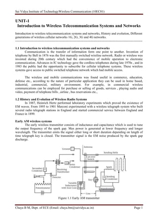
Early AM wireless systems
The early wireless transmitter consists of inductance and capacitance which is used to tune
the output frequency of the spark gap. Max power is generated at lower frequency and longer
wavelength. The transmitter emits the signal either long or short duration depending on length of
time telegraph key is closed. The transmitter signal is the EM noise produced by the spark gap
discharge.
Figure 1.1 Early AM transmitter
2. Sai Vidya Institute of TechnologyWireless Communication (10EC81)
Chaya B M, Dept. of ECE (Email: chaya.bm@saividya.ac.in) Page 2
The transmitter signal propagates through the air to a receiver which is located at some
distance. At the receiver the detected signal is interpreted by the operator as either a dot or dash
depending upon its duration by use of Morse code.
Modern AM:
Amplitude modulation is used for low frequency radio broadcasting the AM include
quadrature amplitude modulation which is used for high speed data transmission at RF frequencies.
1.2 The Development of Modern Telecommunications Infrastructure
The early days of telecommunications
The public switched telephone network
• The local exchange
• Intra-office calls
Fig: 1.2 A PSTN intra office call through a local exchange
– Circuit-switched calls
– Interoffice calls
– T-carrier transport
Within a local exchange or company office (co) a subscriber may be connected to the
exchange in several different ways as shown in fig 1.2. For plain old telephone service the
subscriber may be connected through a local loop connection consisting of a pair of copper wires.
In this case dialing information signal are interpreted by the local exchange switch to set up
the correct pathway or connection through the switch to the desired called party. Call signaling
information is sent to the called party and also back to the caller
For an intraoffice call between two subscribers connected to the same switch, the analog
voice signal from the subscriber’s telephone propagates through the copper pair to a line card
located at the switch.
3. Sai Vidya Institute of TechnologyWireless Communication (10EC81)
Chaya B M, Dept. of ECE (Email: chaya.bm@saividya.ac.in) Page 3
A PSTN interoffice call :
Fig: 1.3 A PSTN interoffice call over an inter-exchange trunk line
Interoffice call is in between calling and called party are connected to a different switch at
another exchange within the same calling area. The signal from the calling subscriber’s switch is
timed through the switch in such a fashion that it is eventually forwarded to a multiplexer and then
transmitted over a digital interoffice transmission facility (Trunk line).
This interoffice might use some type of T-carrier transport topology that might be carried
over copper wires. If the party to be called is in a different calling area, the local switch will
forward the callers packets to a long distance carrier multiplexed facilities using area code of the
called number to direct the call.
Signaling System #7 protocol:
It is a packet network that consists of:
• Signal transfer points
• Service switching points
• Service control points
• Operations support systems
Signaling System #7 (SS7) is a set of telephony signaling protocols which are used to set up most
of the world's public switched telephone network telephone calls.
The main purpose is to set up and tear down telephone calls.
Other uses include number translation, local number portability, prepaid billing
mechanisms, short message service (SMS), and a variety of other mass market services.
It is usually referenced as Signaling System No. 7 or Signaling System #7, or simply
abbreviated to SS7. In North America it is often referred to as CCSS7, an abbreviation for
Common Channel Signaling System 7.
In some European countries, specifically the United Kingdom, it is sometimes called C7
(CCITT number 7) and is also known as number 7 and CCIS7 (Common Channel
Interoffice Signaling 7). In Germany it is often called as N7 (Signaling system Number 7).
4. Sai Vidya Institute of TechnologyWireless Communication (10EC81)
Chaya B M, Dept. of ECE (Email: chaya.bm@saividya.ac.in) Page 4
There is only one international SS7 protocol defined by ITU-T in its Q.700-series
Recommendations.
There are however, many national variants of the SS7 protocols. Most national variants are based
on two widely deployed national variants as standardized by ANSI and ETSI, which are in turn
based on the international protocol defined by ITU-T. Each national variant has its own unique
characteristics. Some national variants with rather striking characteristics are the China (PRC) and
Japan (TTC) national variants.
The Internet Engineering Task Force (IETF) has also defined level 2, 3, and 4 protocols that
are compatible with SS7:
Message Transfer Part (MTP) level 2 (M2UA and M2PA)
Message Transfer Part (MTP) level 3 (M3UA)
Signaling Connection Control Part (SCCP) (SUA)
The public data network
• Connectionless systems
• Private data networks
• Virtual private data networks
• Tunneling protocols
Fig: 1.4 Network elements of the SS7 system
1.3 Different Generations of wireless cellular networks:
1G Cellular Systems
– Advanced Mobile Phone System (AMPS) system components and layout
• Radio base stations
• Communications links
• Mobile switching office
5. Sai Vidya Institute of TechnologyWireless Communication (10EC81)
Chaya B M, Dept. of ECE (Email: chaya.bm@saividya.ac.in) Page 5
First-generation cellular systems have been around for a few decades now, and we expect
them to remain in place for some time because of the significant infrastructure investments
made by operators.
All of these systems support circuit data services and may be utilized for various forms of
mobile VPN, albeit not without difficulties. This section provides a high-level overview of
the air interfaces utilized by most widely deployed 1G systems.
AMPS Technology:
All 1G cellular systems rely on analog frequency modulation for speech and data
transmission and in-band signaling to move control information between terminals and the rest of
the network during the call. Advanced Mobile Phone
System is a good example of first-generation analog technology mostly used in the United
States. AMPS are based on FM radio transmission using the FDMA(Frequency Division Multiple
Access) principle where every user is assigned their own frequency to separate user channels within
the assigned spectrum. FDMA is based on narrowband channels, each capable of supporting one
phone circuit that is assigned to a particular user for the duration of the call. Frequency assignment
is controlled by the system, and transmission is usually continuous in both uplink and downlink
directions. The spectrum in such systems is allocated to the user for the duration of the call,
whether it is being used to send voice, data, or nothing at all.
As with other 1G technologies, in AMPS a circuit represented by a portion of spectrum is
allocated to the user and must remain available for this user, similar to the telephone copper pair
used for voice communications. Similar to the analog wireline connection, a modem is also used
for data access. Error correction protocols used by wireless modems tend to be more robust than
their landline counterparts, because of the necessity of dealing with a more challenging physical
environment with inherently higher interference and signal-to-noise ratios than copper or fiber. The
peak data rate for an AMPS modem call under good conditions is usually up to 14.4 Kbps, and as
low as 4.8 Kbps under poor condition
CHARACTERISTICS OF AMPS:
1. The AMPS system frequency range is 800 MHz
2. Downlink or forward band was from 824-849hz
3. Uplink or reverse band was from 869 -894hz
4. Channel spacing – 30Khz
5. It has two bands named A and B.
6. Both A and B consisted of 333 channels , where 1-312 are traffic channels and 313-333 are
control channels in band A
7. In band B , 355-666 for traffic channels and 334-354 for control channels
.
Figure 1.5 An early AMPS cellular system
6. Sai Vidya Institute of TechnologyWireless Communication (10EC81)
Chaya B M, Dept. of ECE (Email: chaya.bm@saividya.ac.in) Page 6
The typical AMPS cellular system consist of following components:
Several to many base stations, many mobile stations and a mobile telephone switching office
(MTSO).
The base stations are connected to the MTSO that is in turn connected to the public telephone
network (PSTN).
The base station and mobile station provide air interface that permits subscriber mobility while
connected to the PSTN.
The MSC performs system control by switching calls to the correct cells. The base station provides
the interface between the MSC and the mobile subscriber.
The base station receives both signals and instructions from MSC that allow it to receive and send
traffic to the mobile station.
Information flow over AMPS channels
– Analog color codes
– Digital color codes
– Transponder
– Signaling tones
Different channels of AMPS are shown in above diagram 1.6. AMPS consists of following
channels
Control channel: 1. FOCC (Forward Control Channel) Data Channel: 1. FVC
2. RECC (Reverse Control Channel) 2. RVC
Control channel is required to exchange control information from mobile station to base station.
Control channels are used by the mobile and base station to set up and clear calls and other network
operation.
FOCC and RECC is used to transmit signaling info, control messages and DCC (Digital
Color Code) from base station to mobile station.
Fig 1.6 AMPS forward and reverse control and voice channels
7. Sai Vidya Institute of TechnologyWireless Communication (10EC81)
Chaya B M, Dept. of ECE (Email: chaya.bm@saividya.ac.in) Page 7
Figure shows the flow of information over these channels:
When the mobile station engaged in a voice call control and signaling information may also be
transmitted over the traffic channels (FVC and RVC) being used be the mobile and base station.
Signaling info is in the form of supervisory audio tones (SAT) also called as analog color codes.
Three SAT frequencies are used: 5970 Hz, 6000hz and 6030 Hz. These tones are used to keep
informed about base station and mobile station transmitting capabilities. The base station
periodically adds a SAT signal to the FVC, thus transmitting it to the mobile station. Mobile station
acts like transponder, transmits the same frequency tone on the reverse voice channel (RVC)
Similar function is performed be the transmission of digital color code over the forward
control channel by the base station over the reverse control channel by the mobile station.
Additionally a signaling tone (ST) of 10 kHz can be transmitted over a voice channel to
confirm orders and to signal various requests.
Each FOCC message can consists of one or more words. The type of messages to be transmitted
over FOCC are overhead messages, mobile station control messages and control-filler messages.
Overhead message information is used to allow mobile stations to perform the
initialization task, to update Mobile stations that are monitoring a control channel.
The mobile station control messages consists of order messages that initiates the particular
operation.
The control-filler message consists of Space filler that is sent whenever there is no other
message to be sent on the FOCC.
Typical AMPS operation:
Fig 1.7 AMPS mobile phone initialization
When the mobile phone is first powered up it goes through initialization process
1. The cellular phone sets itself to cellular provider A or B.
2. The scanning of 21 control channels of the selected service provider’s system by the mobile
phone and selects the strongest control channel to lock onto.
3. Updating of overhead information by the mobile station should takes place in three seconds.
If not, it starts from task 1.If update is completed in 3 seconds, it proceeds to next task.
4. The mobile station has to scan the paging channels of the system and then lock onto the
strongest paging channel. If task 4 cannot complete, the mobile returns to task 1 and starts
over.
8. Sai Vidya Institute of TechnologyWireless Communication (10EC81)
Chaya B M, Dept. of ECE (Email: chaya.bm@saividya.ac.in) Page 8
5. If tasks #1-4 are complete, the mobile will identify or register itself with the network by
sending its ESN, MIN and SID numbers over the RECC.
6. The ID numbers will be compared against a database at the MSC to validate the mobile
station’s ability to have roaming status.
7. Finally the BS sends a control message to the mobile to verify that the initialization process
has been completed.
8. The mobile goes into a idle mode during which it continually performs four ongoing taks.
AMPS ongoing idle mode tasks:
The mobile phone must execute each of the following four tasks every 46.3 milliseconds.
Idle mode#1: Respond to overhead information: The mobile must continue to receive
overhead messages and compare the received SID with the last received SID.
Idle mode #2: Page match. The MS must monitor MS control messages for page
messages. If paged, the mobile enter the system access task with a page response.
Idle mode #3: Order. The MS must monitor mobile station control messages for order. If
orders are received the mobile must respond to it.
Idle mode #4: Call initialization: When mobile subscriber desires to initiate call , the
system access task must be entered with an origination indication.
AMPS mobile originated call
If the mobile subscriber wants to make a call, several handshaking messages must be exchanged
between the mobile phone and base station over the various control channels.
Fig 1.8 AMPS mobile originated call
9. Sai Vidya Institute of TechnologyWireless Communication (10EC81)
Chaya B M, Dept. of ECE (Email: chaya.bm@saividya.ac.in) Page 9
The steps shown in the figure is needed to complete this task as shown in the above figure.
AMPS mobile terminated call
The mobile station can receive a call from another mobile or from a telephone connected to the
PSTN (a landline).
The following Handshaking steps are shown:
Fig 1.9 AMPS mobile terminated call
1. The network (MSC) sends the ID of the mobile station to the Base station.
2. The BS constructs page control message and the ID information (ESN, MIN, SID) is added
to the message as initial voice channel information.
3. The mobile station responds to the page by returning Identification information over the
RECC in a page response message.
4. SCC value is sent inform the mobile as to correct SAT to be used on the voice channel.
5. The base and mobile station both switch to the voice channels.
6. SAT tones to verify the radio link (step 6 and 7)
7. After this last handshake occurs, the traffic channel is then opened to conversation.
10. Sai Vidya Institute of TechnologyWireless Communication (10EC81)
Chaya B M, Dept. of ECE (Email: chaya.bm@saividya.ac.in) Page 10
AMPS network operations:
At this time, it will be instructive to look at what is happening on the network side of the cellular
system.(base station to MSC and MSC to PSTN operations)
• Radio base station operations
• Base station control operations
• Mobile switching center operations
Figure below shows the details of these operations.
Fig 1.10 AMPS network operations for a mobile originated call
11. Sai Vidya Institute of TechnologyWireless Communication (10EC81)
Chaya B M, Dept. of ECE (Email: chaya.bm@saividya.ac.in) Page 11
AMPS Handoff operations:
A handoff operation occurs in a cellular system when a mobile station moves to another cell. Figure
shows the details of the handshaking operations that take place for handoff to occur.
Fig 1.11 AMPS handoff operation
In this case, the Mobile switching center connected to two or more base stations within
some geographic area.
Consider Base station A is handling an active call from Mobile station within its area of
coverage. The mobile station is in transit and is moving away from Base station A to Base
station B’s coverage area.
When the signal received power from the mobile station goes below some threshold level,
BS A sends the handoff measurement request to MSC. The MSC requests all the nearest
BS’s and it determines that BS B has strongest signal from the mobile. Now the MSC
assigns a traffic channel (TCH) to Base station B.
12. Sai Vidya Institute of TechnologyWireless Communication (10EC81)
Chaya B M, Dept. of ECE (Email: chaya.bm@saividya.ac.in) Page 12
Base station B responds and sends handover order from MSC to Base station A. Base
station A is now assigned with new channel with new output power. As before, the mobile
receives the Base station B’s SAT and returns it.
AMPS Security and Identification:
Three identification numbers are used by the AMPS system
1. Mobile station’s electronic serial number (ESN): ESN is provide by phone’s manufacturer
and is not able to be easily altered.
2. Service provider’s system identification number (SID):15 bit binary number that is uniquely
assigned to cellular systems.
3. Mobile stations mobile identification number (MIN): MIN is a 34 bit binary number derived
from the mobile station’s 10 digit telephone number.
2G Cellular Systems
Second-generation (2G) digital cellular systems constitute the majority of cellular
communication infrastructures deployed today. 2G systems such as GSM, whose rollout started in
1987, signaled a major shift in the way mobile communications is used worldwide. In part they
helped fuel the transition of a mobile phone from luxury to necessity and helped to drive subscriber
costs down by more efficient utilization of air interface and volume deployment of infrastructure
components and handsets.
Major geographical regions adopted different 2Gsystems, namely TDMA and CDMA in
North America, GSM in Europe, and Personal Digital Cellular (PDC) in Japan. Cellular systems. It
effectively shows how the GSM system has been successful and why it is now being adopted in
geographical areas other than Europe (such as North America, China, the Asia-Pacific region, and
more recently, South America). CDMA, which originated in North America, has also proliferated
in South America and later in the Asia Pacific region. TDMA remains to be widely deployed in
North and South America regions, but it is expected to decline mostly because of the decisions
taken by few major North American carriers to convert their TDMA networks to GSM.
This second-generation system, widely deployed in the United States, Canada, and South
America, goes by many names, including North American TDMA, IS-136, and D-AMPS (Digital
AMPS).
2G cellular systems are classified into two categories:
TDMA has been used in North America since 1992, it is based on Time Division Multiple
Access. In TDMA the resources are shared in time, combined with frequency-division
multiplexing (that is, when multiple frequencies are used). As a result, TDMA offers
multiple digital channels using different time slots on a shared frequency carrier. Each
mobile station is assigned both a specific frequency and a time slot during which it can
communicate with the base station.
The TDMA transmitter is active during the assigned time slot and inactive during other time
slots, which allows for power-saving terminal designs, among other advantages.
The technologies developed based on TDMA are GSM, PDC etc.
CDMA –Code division Multiple Access developed by QUALCOMM corporation. use a
digital modulation techniques known as spread spectrum, In this system, at the transmitter ,
each user’s digitally encoded signal is further encoded by a special code that converts each
bit of original digital message into many bits.
At the receiver, same special code is used to decode or recover the original bit stream
special codes used to perform this encoding / decoding function have the unique property
13. Sai Vidya Institute of TechnologyWireless Communication (10EC81)
Chaya B M, Dept. of ECE (Email: chaya.bm@saividya.ac.in) Page 13
that each received signal looks like noise to a receiver that does not share the same code as
transmitter of the signal.
Global System for Mobile Communications (GSM)
There are still some analog cellular systems in operations in Europe, but their number is declining,
and some regional networks are being completely shut down or converted to Global System for
Mobile Communications.
The GSM cellular system initiative was initiated in 1982 by the Conference of European
Posts and Telecommunications, Administrations (CEPT) and is currently governed by
European Telecommunications.
The first GSM original scheduled in 1991, began operating in 1992. Before the end of 1993,
1 million customers had signed up for service.
72 percent of world’s cellular customers subscribing to the service of GSM Technology.
GSM uses a transmission format with eight time slots and therefore system can support 8
users/ radio channel simultaneously.
There are 500 GSM networks in operation in 174 countries with 1 billion users as of 2004.
PDC-Personal Digital communications
Japanese ministry of Post and telegraph developed PDC in 1991. PDC systems supplied by
Motorola were deployed starting in 1993.
The PDC systems had weak broadcasting, Allowed service only for portable phone with
light batteries and had problems in maintaining connections.
It used 800 M Hz frequency band and had 46 million subscribers as of 2005.
PCS- Personal Communication Services
FCC Allocated 153 MHZ of spectrum for PCS.
In only a limited number of cases, service providers have deployed pure PCS
networks. Eg.,Sprint PCS and T-Mobile.
CDMA, GSM 1900 and NA-TDMA technology have been used to provide service
in there PCS bands.
PCS is for mobile users and requires a number of antennas to blanket an area of
coverage. As a user moves around, user’s phone signal is picked up by nearest
antennas and then forwarded to a BS that connects to wired network.
It is a wireless phone service similar to cellular telephone service hence it is called
as digital cellular.
2.5g Cellular Systems
"2.5G" is an informal term, invented solely for marketing purposes, unlike "2G" or "3G"
which are officially defined standards based on those defined by the International
Telecommunication (ITU).
The term "2.5G" usually describes a 2G cellular system combined with General Packet
Radio Services (GPRS), or other services not generally found in 2G or 1G networks.
Wireless telecommunication technology like CDMA200 1xRTT, Enhanced Data Rates for
GSM Evolution (EDGE) or Enhanced General Packet Radio Service (EGPRS), since they
have data transmission rates of 144 kbps or higher, may qualify as 3G technology.
However, they are usually classified as 2.5G technology because they have slower network
speeds than most 3G services.
14. Sai Vidya Institute of TechnologyWireless Communication (10EC81)
Chaya B M, Dept. of ECE (Email: chaya.bm@saividya.ac.in) Page 14
CDPD -Cellular Digital Packet Data:
It is designed to provide mobile packet data services. It was a wide area mobile data
service which used unused bandwidth normally used by AMPS mobile phones between
800MHz-900MHz to transfer data.
The speed is up to 19.1Kbps
This service was discontinued in conjunction with the retirement of the parent AMPS
service.
HSCSD-High Speed Circuit Switched Data
It operates on GSM network therefore no extra hardware needed for mobile
communication operator to offer the service.
It just need a network software upgrade.
In GSM single slots are allocated to each user with data band 9.6Kbps ad upgraded to
14.4Kbps, ie., an increase of 50 %.
In HSCSD, the users are allocated multiple slots so that transmission speed can be
increased with same service provider up to 57.6 Kbps.
GPRS-General Packet Radio services
It is an integrated part of GSM. GPRS is a service commonly associated with 2.5G
technology. It has data transmission rates of 28 kbps or higher.
It was succeeded by the development of the Universal Mobile Telecommunication Service
(UMTS), which is classified as 3G technology. A 2.5G system may make use of 2G system
infrastructure, but it implements a packet-switched network domain in addition to a circuit-
switched domain.
The services and infrastructure of a 2.5G network may be used on a per-transaction basis
rather than a per-minute-of-use basis, thanks to its packet-switched domain. This makes its
infrastructure more efficient and improves the service delivery. This impetus is known as
the "always-on" capability.
2.5G networks may support services such as WAP, MMS, SMS mobile games, and search
and directory. GPRS supports services like, SMS messaging, Always on internet access ,
Multimedia message services(MMS).
3G Cellular Systems
3G generation phones were developed in the late 1990s and 2000s. The goal was to improve
the data capability and speed. 3G phones were defined by the Third Generation Partnership
Project (3GPP) and later standardized by the ITU-T.
Generally known as the Universal Mobile Telecommunication System (UMTS).
This 3G system is based on wideband CDMA that operates in 5 MHz of bandwidth and can
produce download data rates of typically 384 kb/s under normal conditions and up to 2
Mb/s in some instances.
Another 3G standard, cdma2000, was developed by Qualcomm. It uses 1.25 MHz bands to
produce data rates to 2 Mb/s. Another version of cdma2000 is an improved IS-95 version. It
is a 3GPP2 standard. It can transmit data at a rate to 153 kb/s and up to 2 Mb/s in some
cases. 3G phone standards have been expanded and enhanced to further expand data speed
and capacity.
The WCDMA phones have added high speed packet access (HSPA) that use higher level
QAM modulation to get speeds up to 21 or 42 Mb/s downlink (cell site to phone) and up to
7 and/or 14 Mb/s uplink (phone to cell site). AT&T and T-Mobile use HSPA technology.
15. Sai Vidya Institute of TechnologyWireless Communication (10EC81)
Chaya B M, Dept. of ECE (Email: chaya.bm@saividya.ac.in) Page 15
The cdma2000 phones added 1xRTT as well as Rev. A and Rev B modifications that boost
speed as well. Verizon and Sprint use cdma2000 3G standard technology. Virtually all
standard and Smartphone models and most tablets still use some form of 3G.
Figure shows the 3G operating environments which explains the architecture of Cellular systems.
Fig 1.12 3G operating environments
4G Cellular Systems and Beyond:
The fourth generation has been defined but we are not in it, yet. Yes, many if not most of
the mobile carriers and the various phone and equipment manufacturers actually advertise
4G now.
The formal definition of 4G as declared by the 3GPP and the ITU-T is something called
Long Term Evolution-Advanced (LTE-A). The standard has not been fully completed but
basically it is an improved and enhanced version of LTE that uses wider bandwidth
channels and a greater number of MIMO antennas. The theoretical upper data rate is 1 Gb/s.
That remains to be seen in practice.
As for what the various companies are calling 4G, Verizon says that their LTE network is
16. Sai Vidya Institute of TechnologyWireless Communication (10EC81)
Chaya B M, Dept. of ECE (Email: chaya.bm@saividya.ac.in) Page 16
4G. AT&T promotes their LTE and HSPA networks as 4G. T-Mobile indicates that their
HSPA+ networks are 4G. Furthermore Sprint and Clear wire say that their WiMAX
network is 4G. As mentioned, WiMAX is actually defined as a 3G technology by ITU-T
like LTE.