Downloaded 134 times

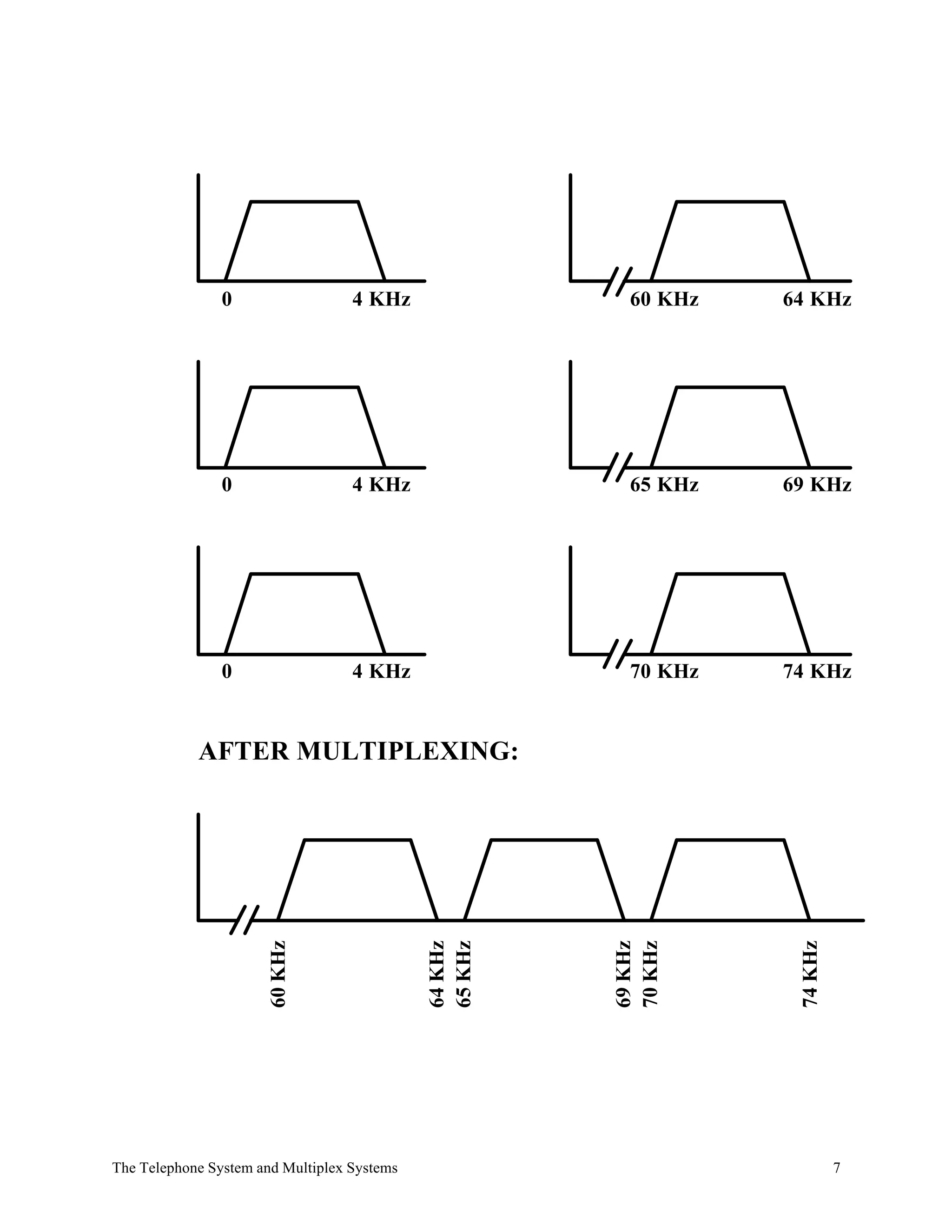
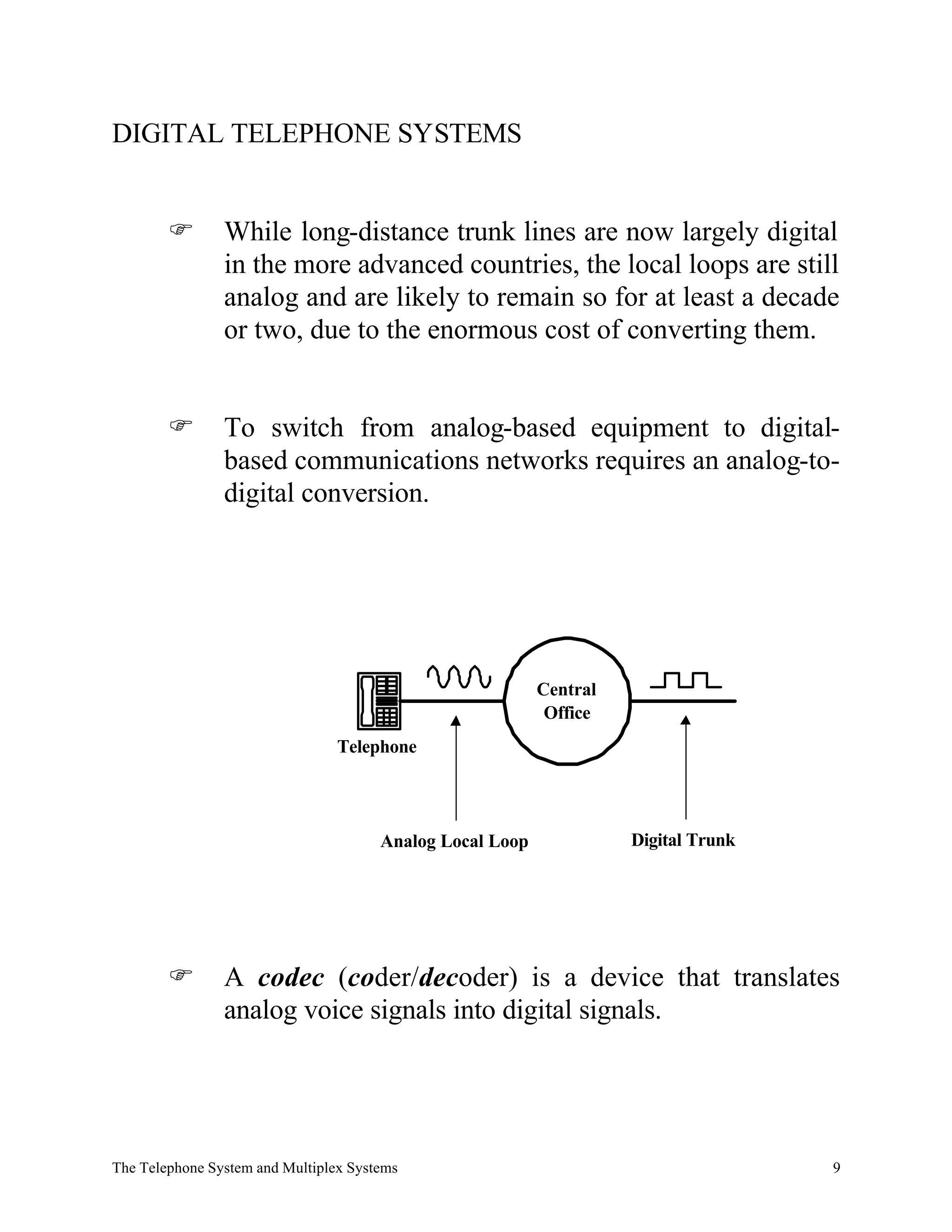
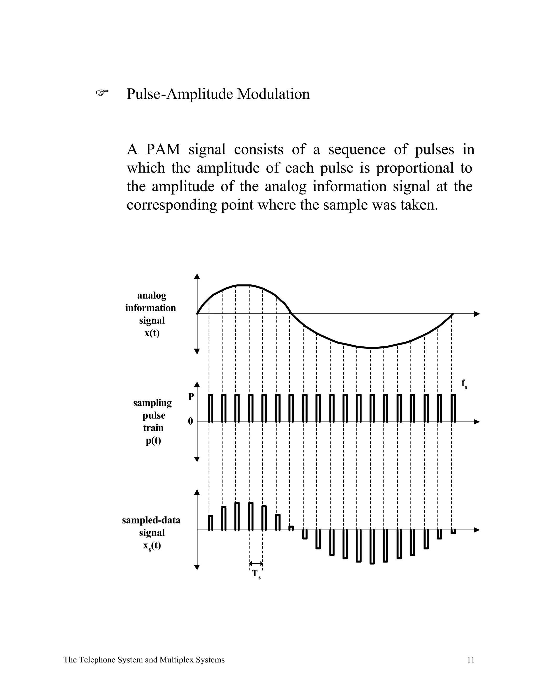

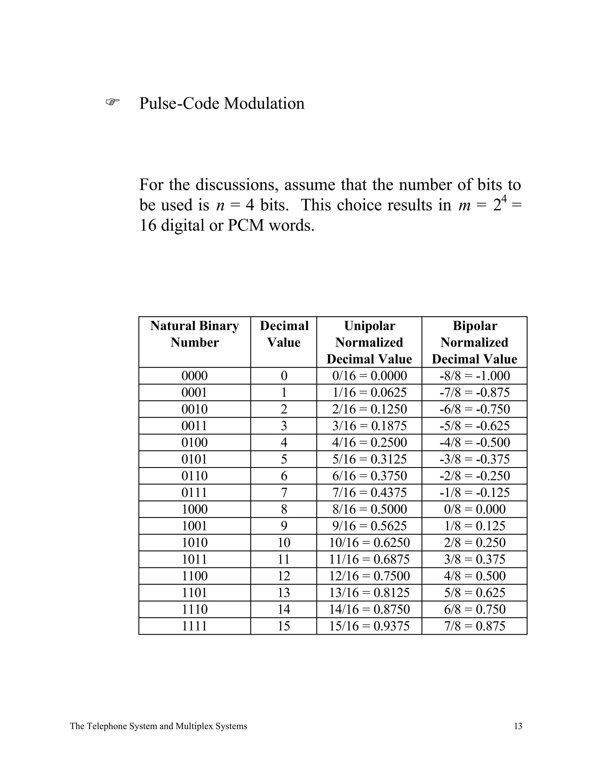


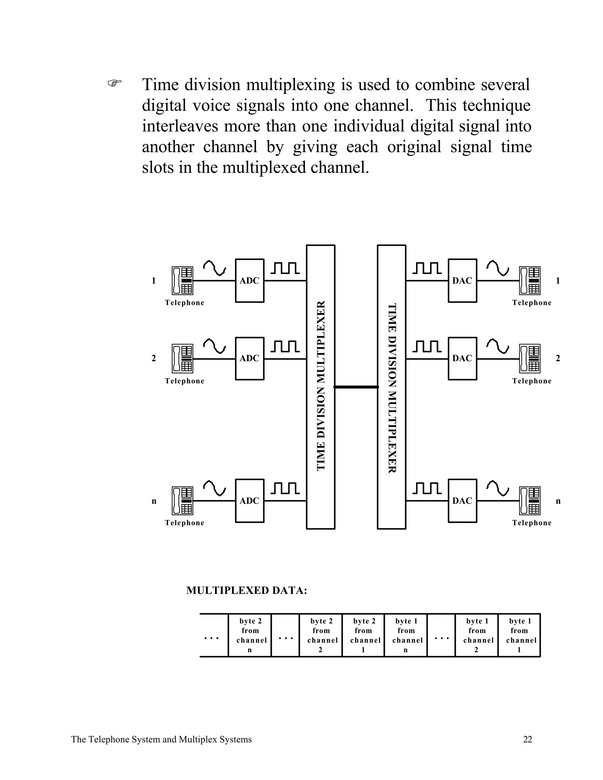
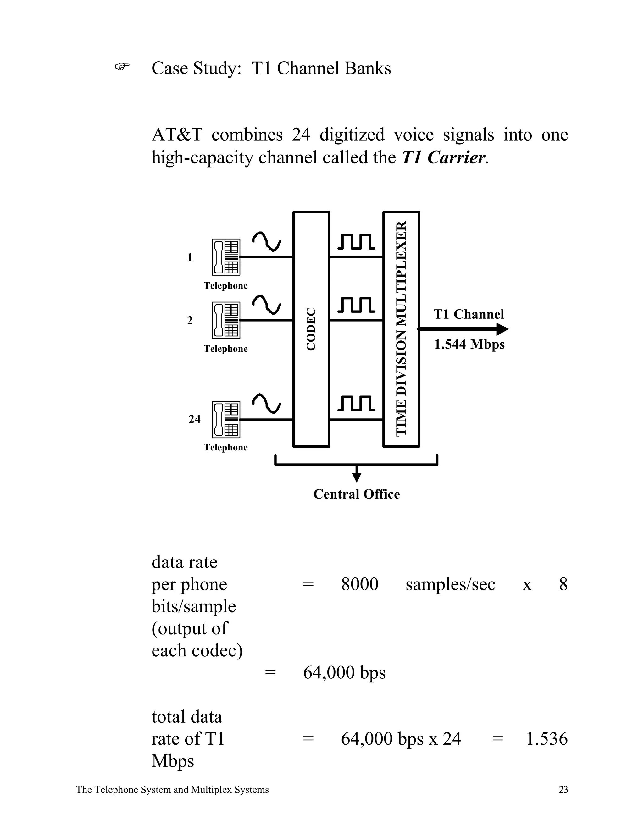


The document discusses analog and digital telephone systems and multiplexing techniques. It provides details on: 1) How analog telephone systems work using local loops and trunk lines to connect central offices. 2) The use of frequency division multiplexing and time division multiplexing to combine multiple signals over telephone lines. 3) How digital telephone systems convert analog signals to digital using pulse amplitude modulation, pulse code modulation, and codecs at central offices. 4) The process of quantization and coding used in pulse code modulation to represent analog signals with digital codes.