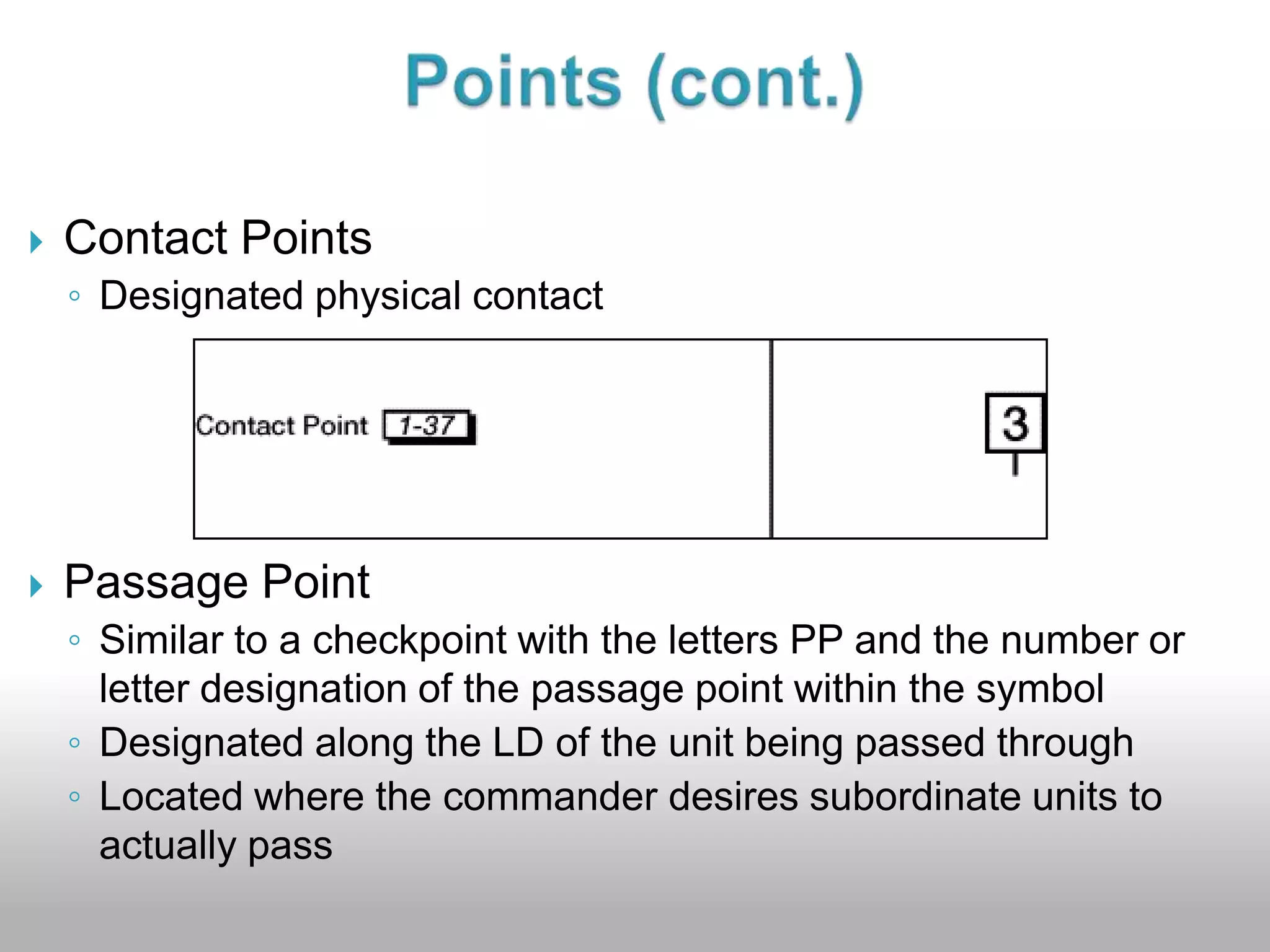
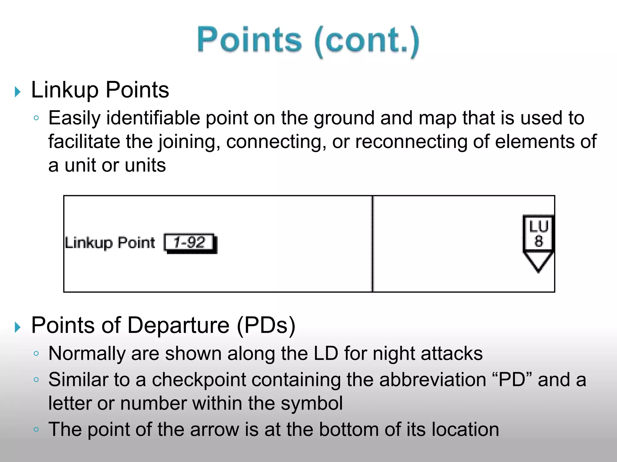
Downloaded 664 times


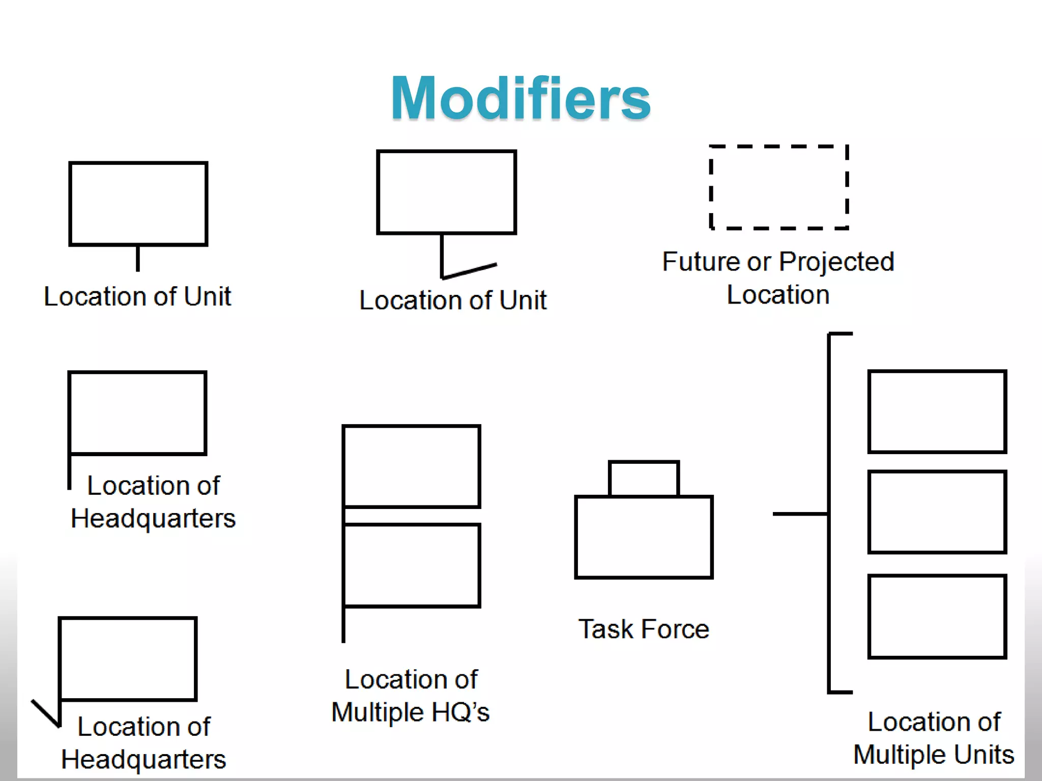


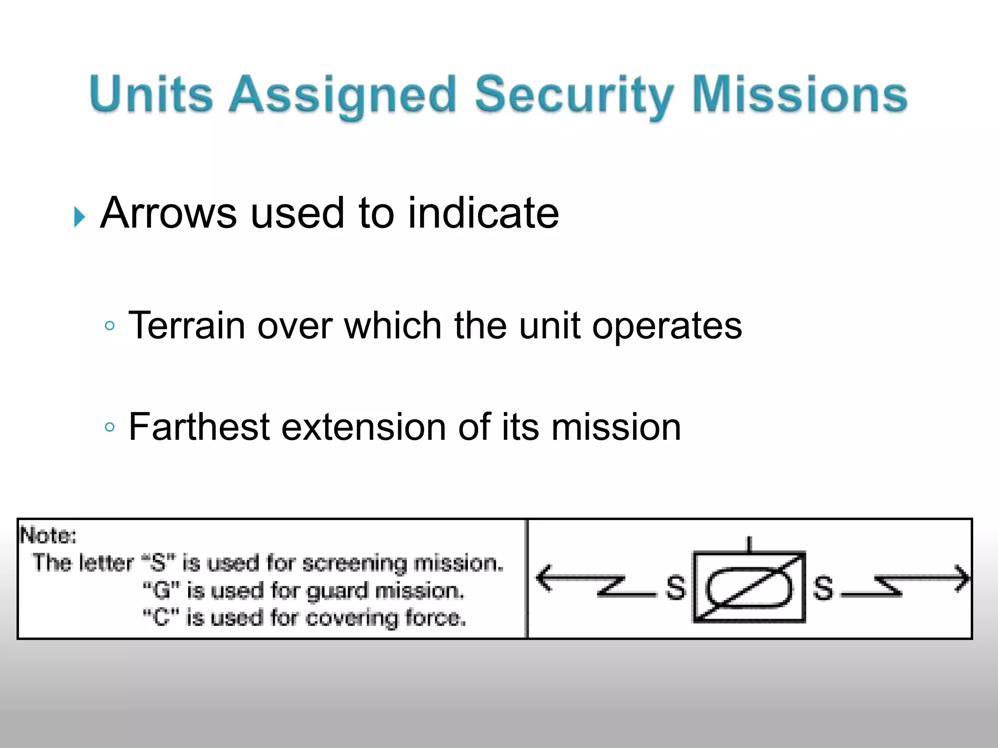
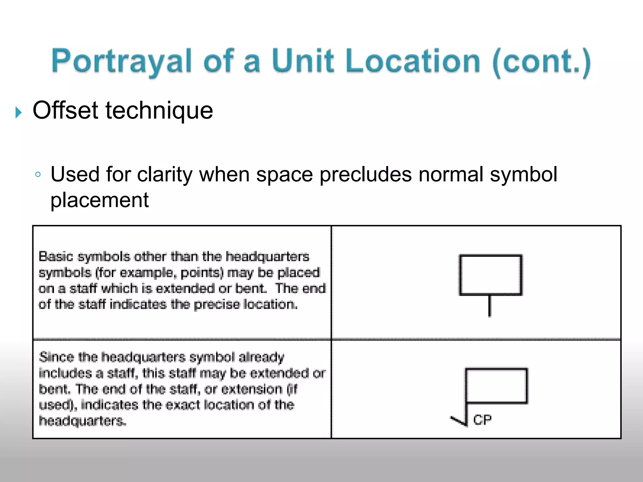
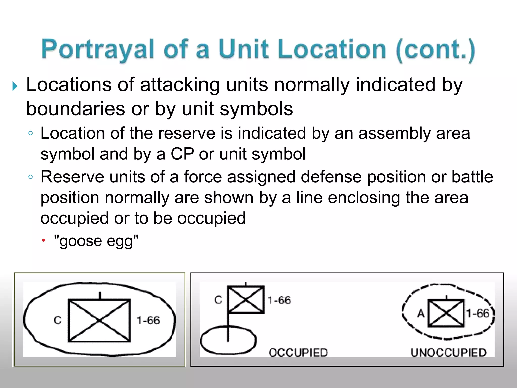
![Offset staffsMay be "bent" as required. Dashed for future or proposed locations Extend vertically from the bottom center of the symbol (except for command posts [CP])End of the offset staff indicates Exact locations of CPs and aid stations Center of mass for other units or installations The staff for a CP symbol is always on the left edgePortrayal of a Unit Location (cont.)](https://image.slidesharecdn.com/071-332-5000prepareanoperationoverlay-110308214135-phpapp02/75/071-332-5000-Prepare-an-Operation-Overlay-38-2048.jpg)
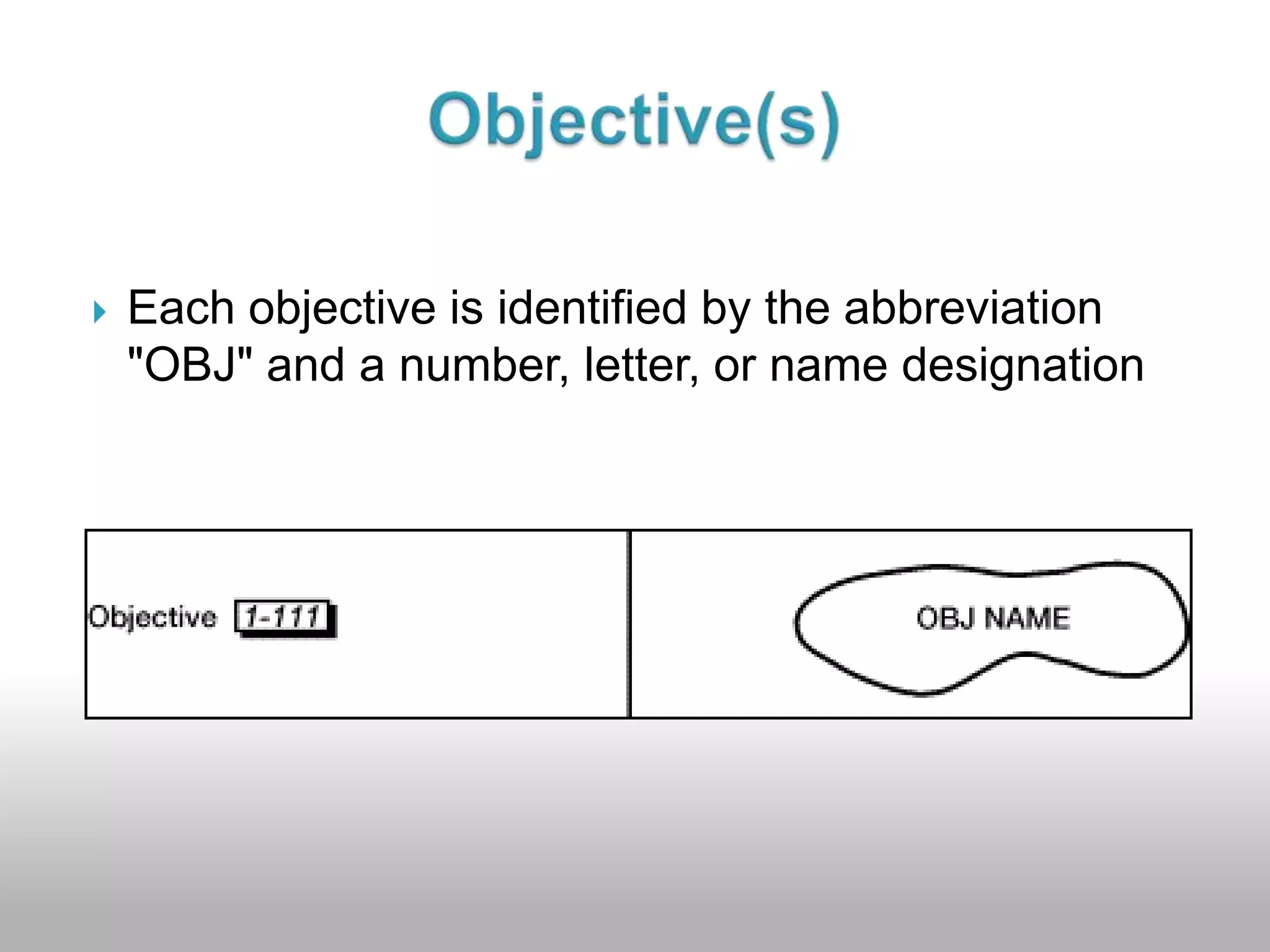
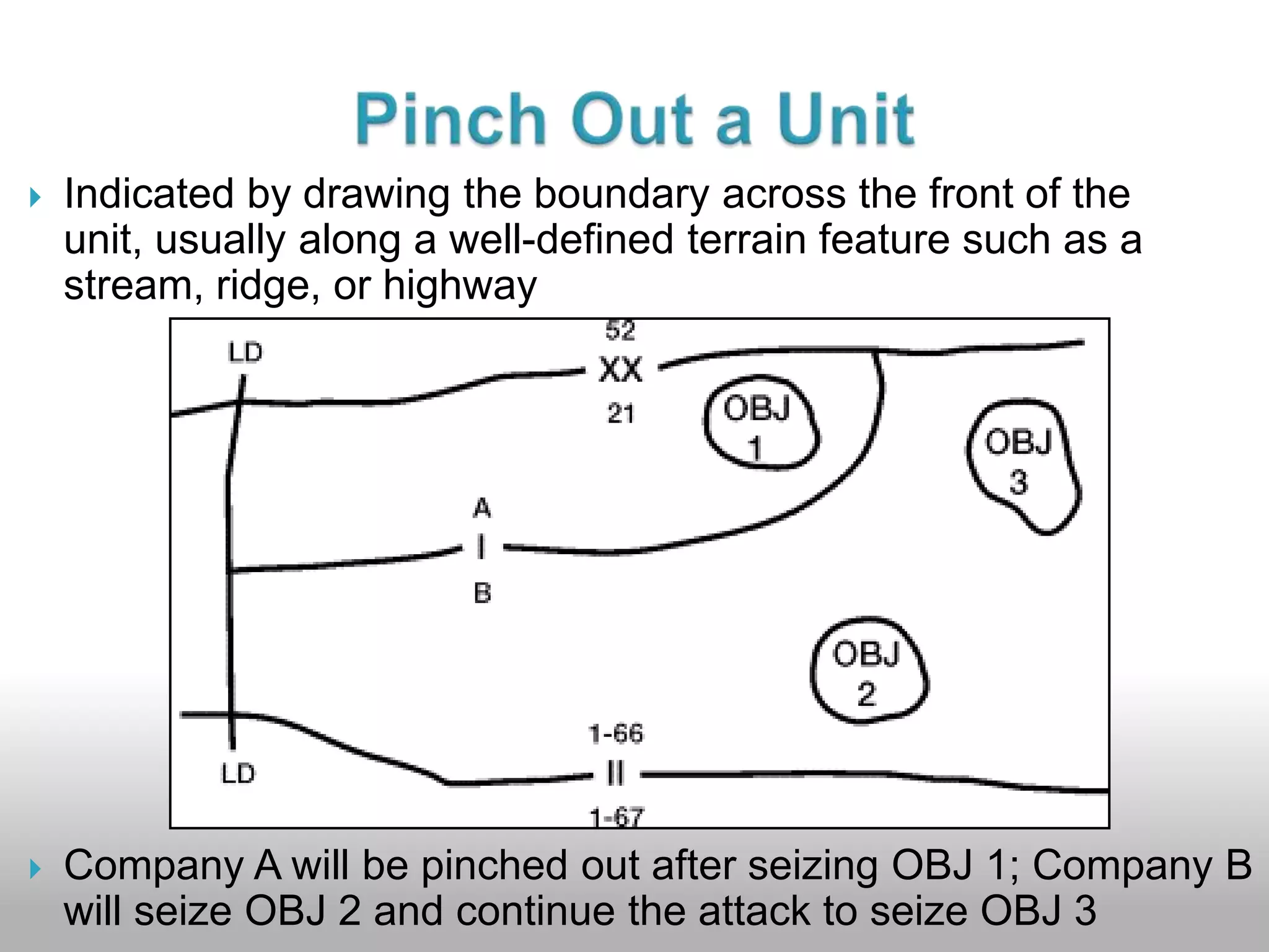
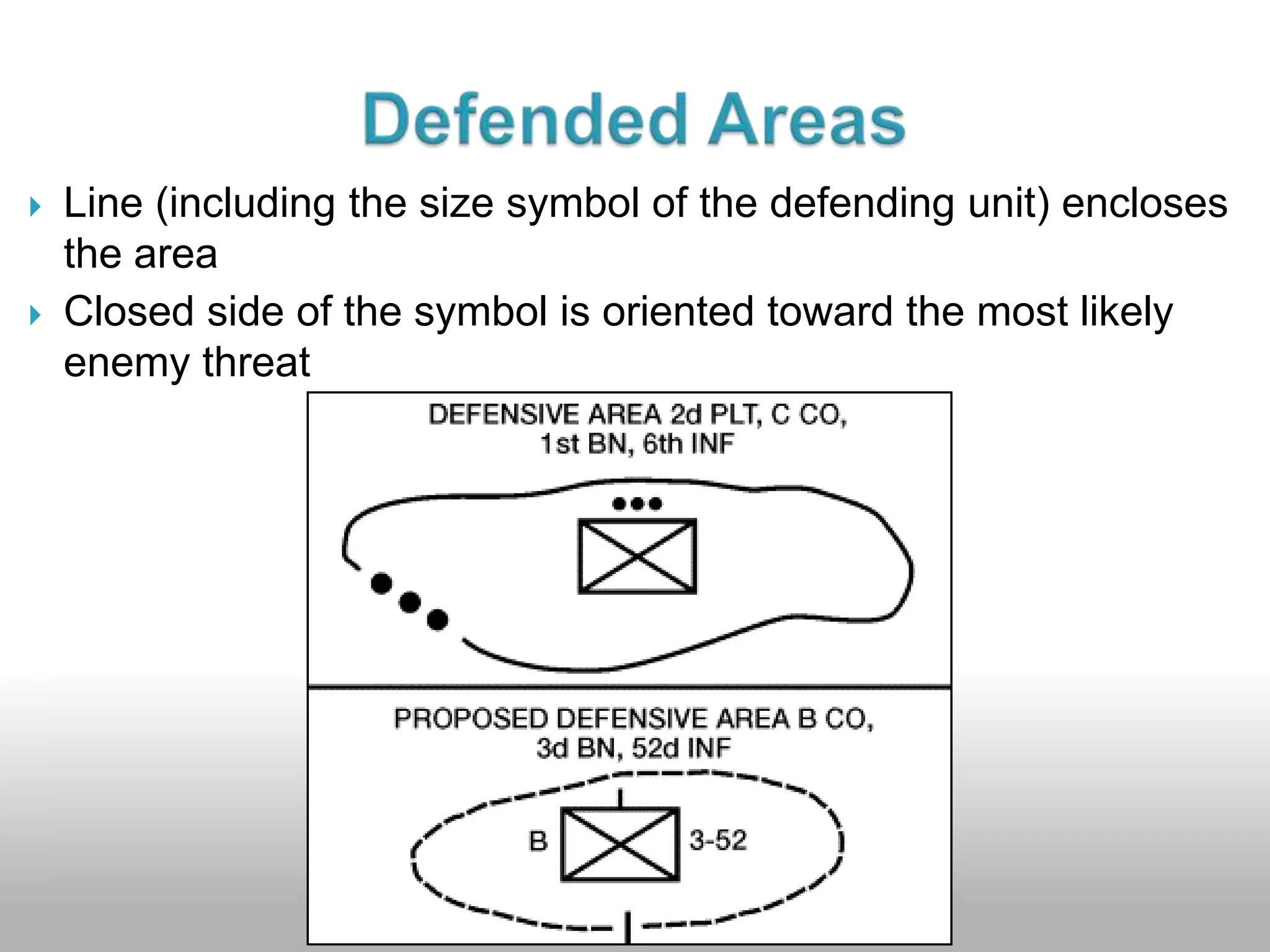


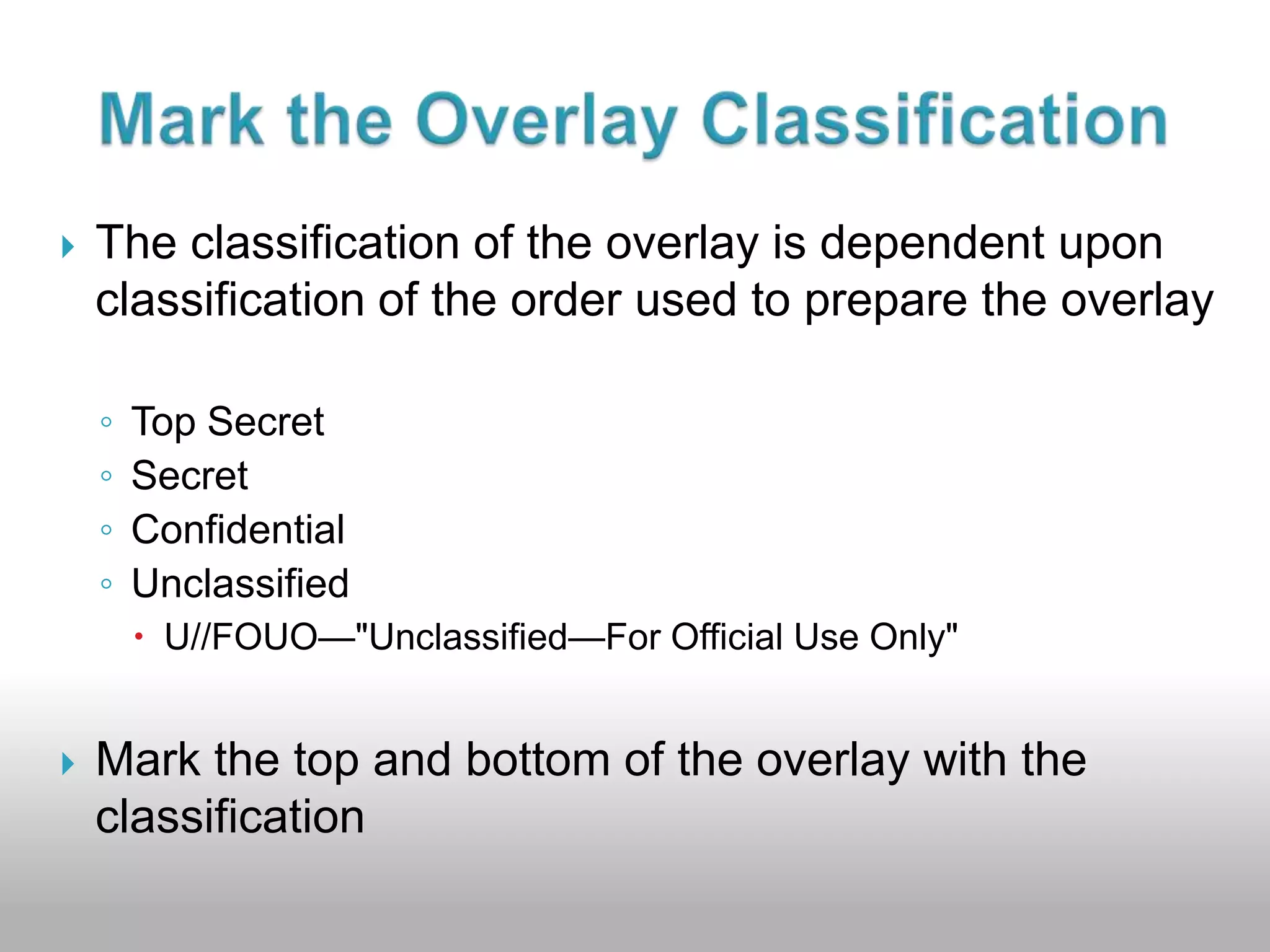
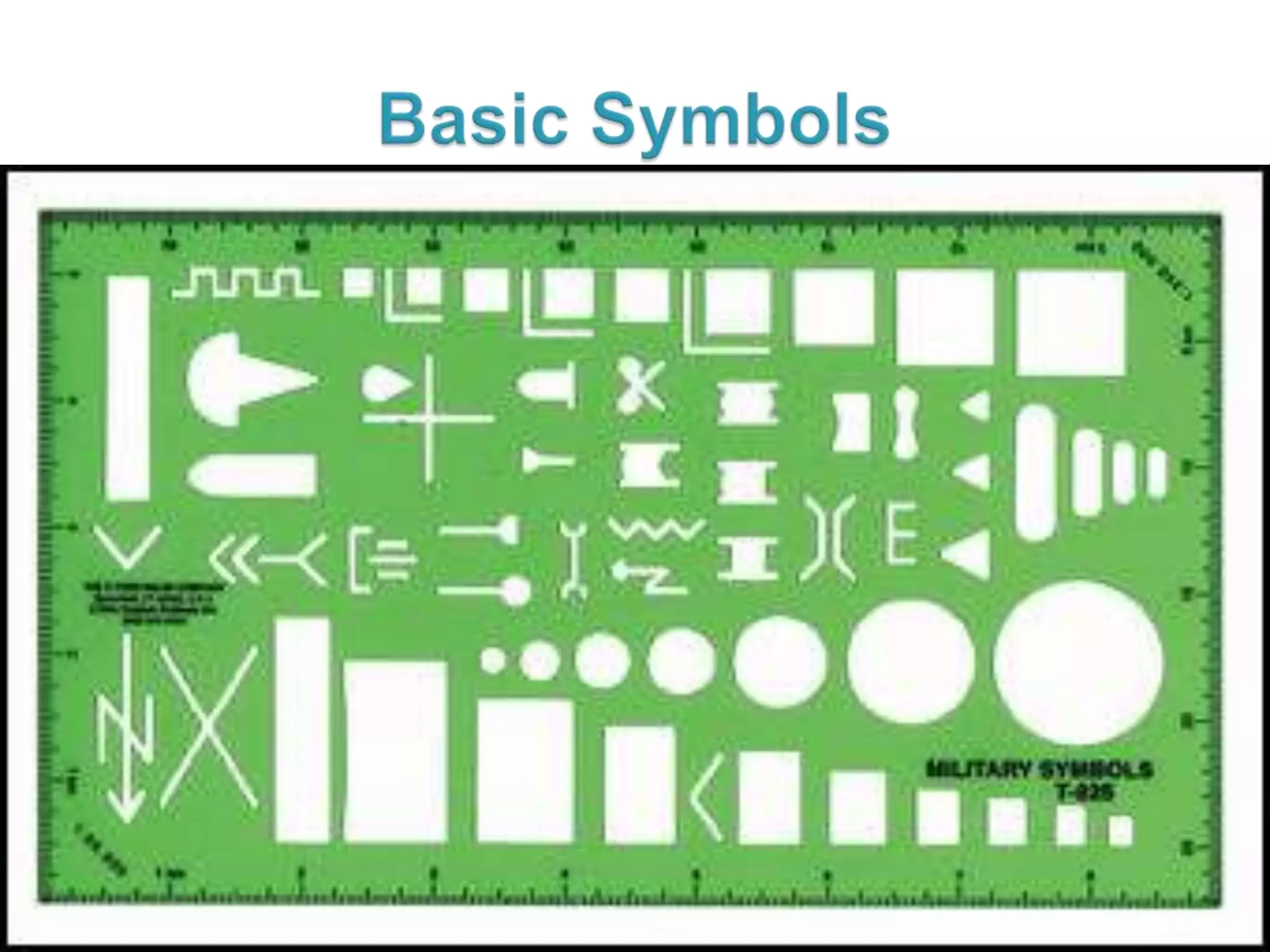
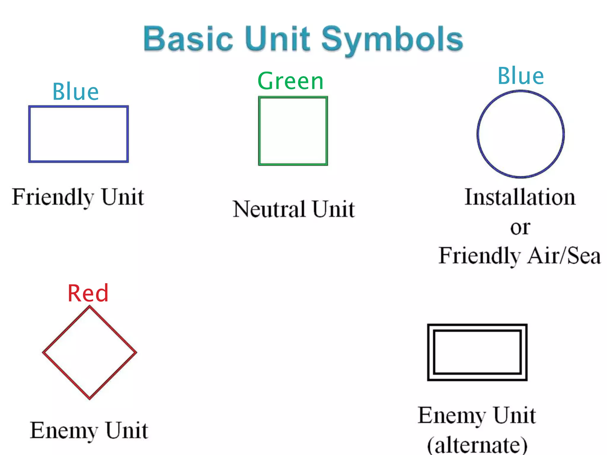
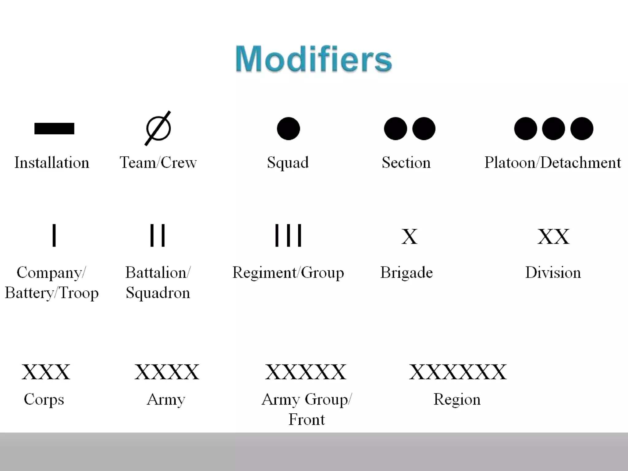
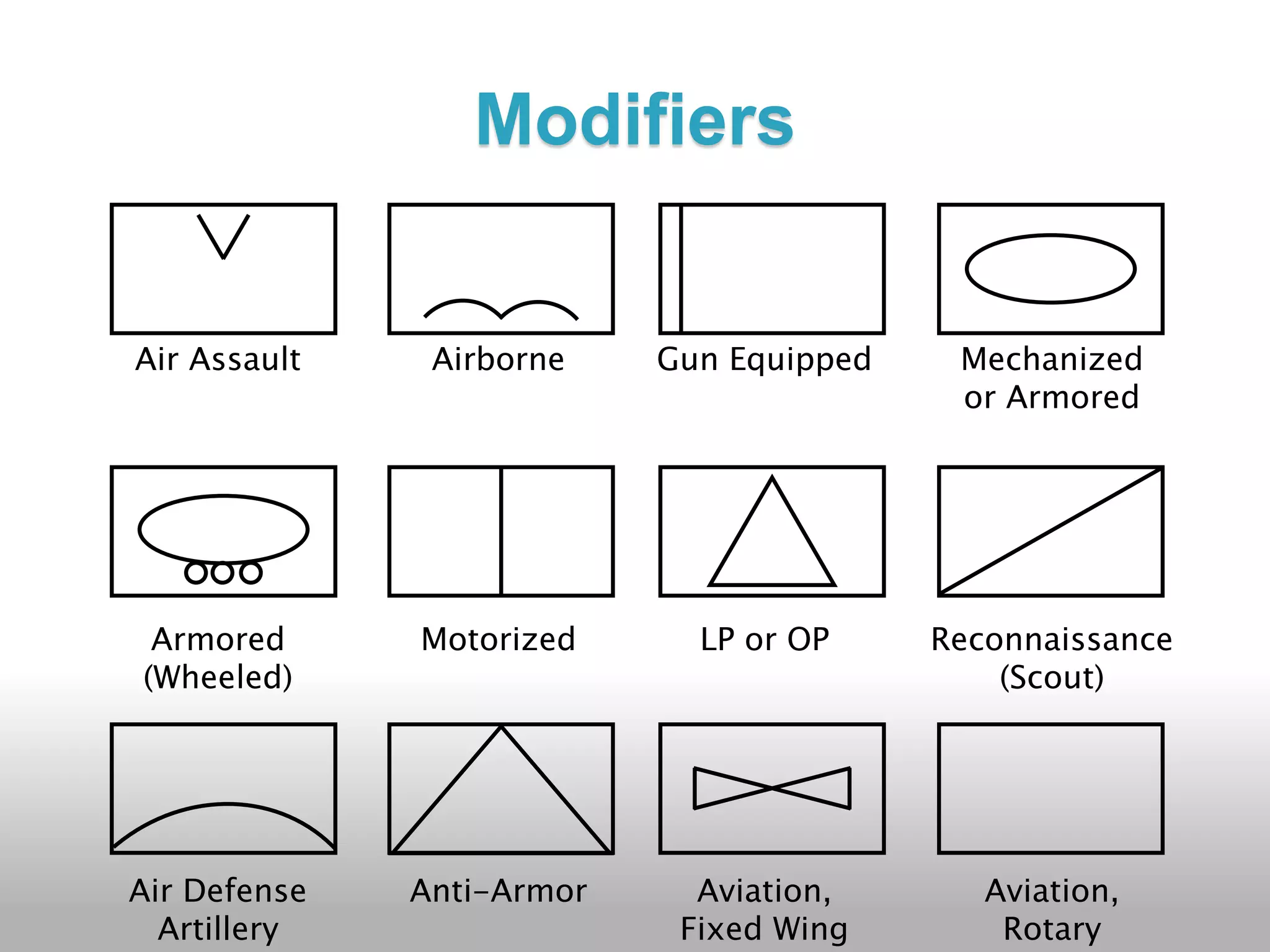
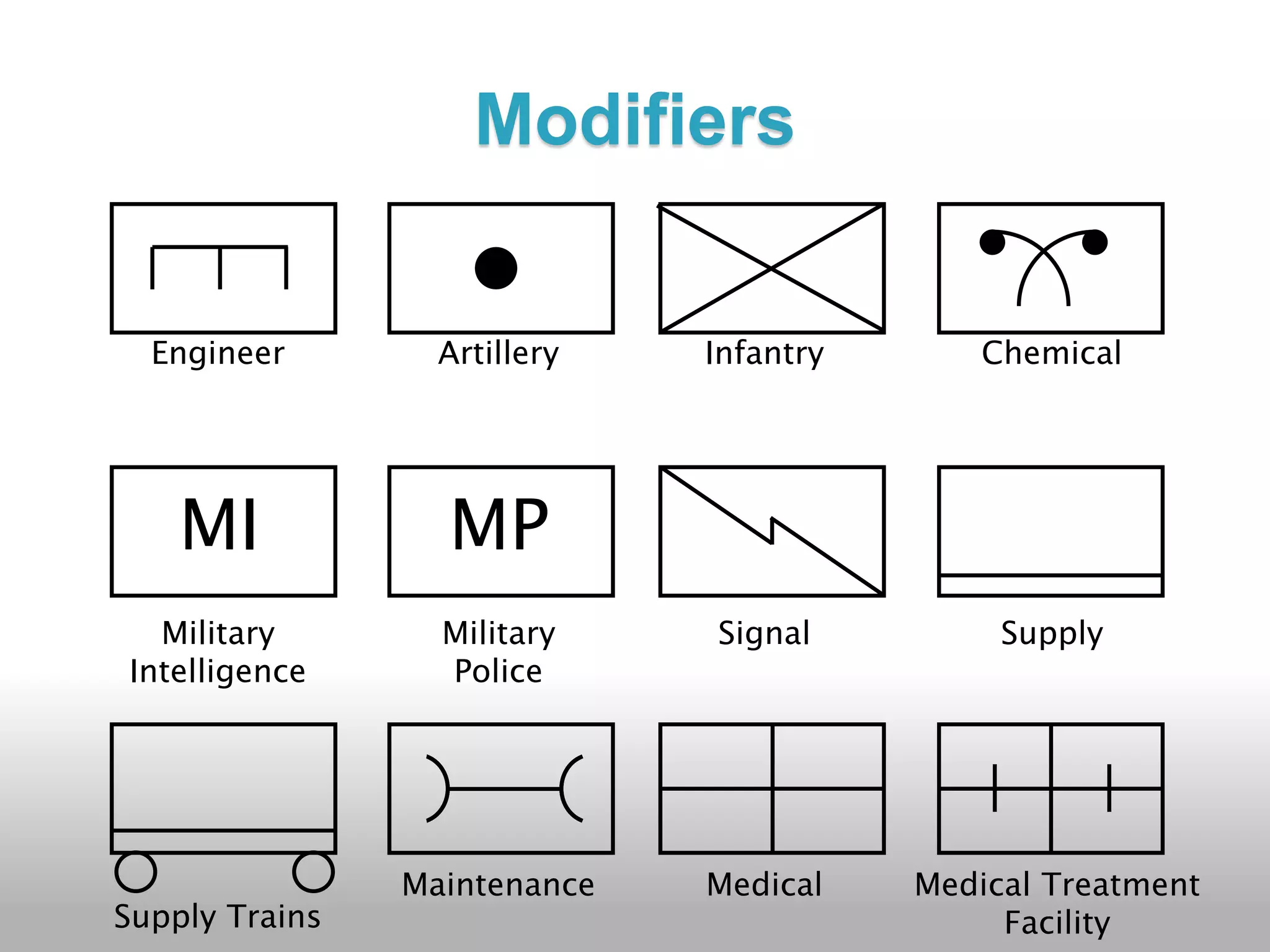
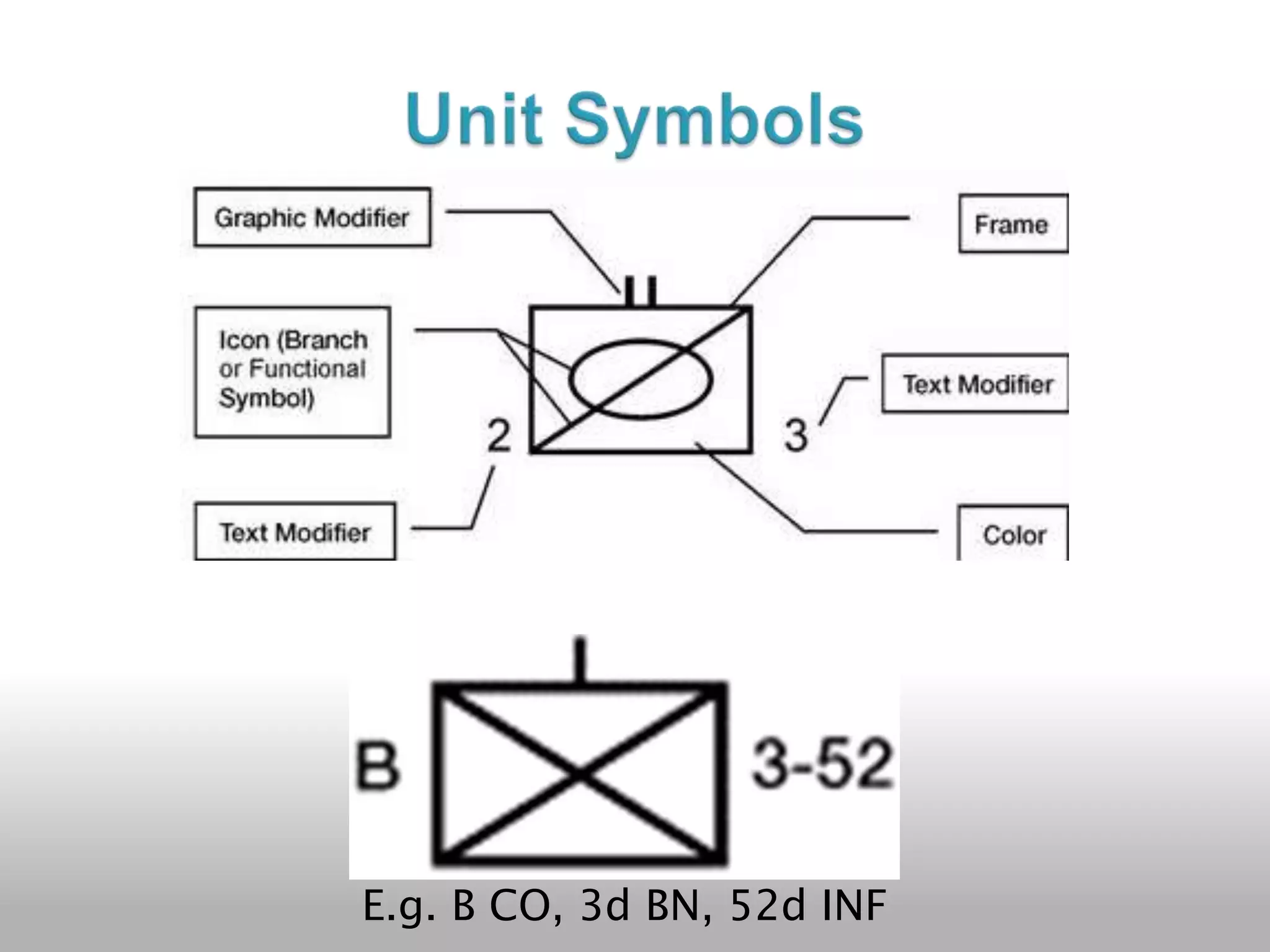
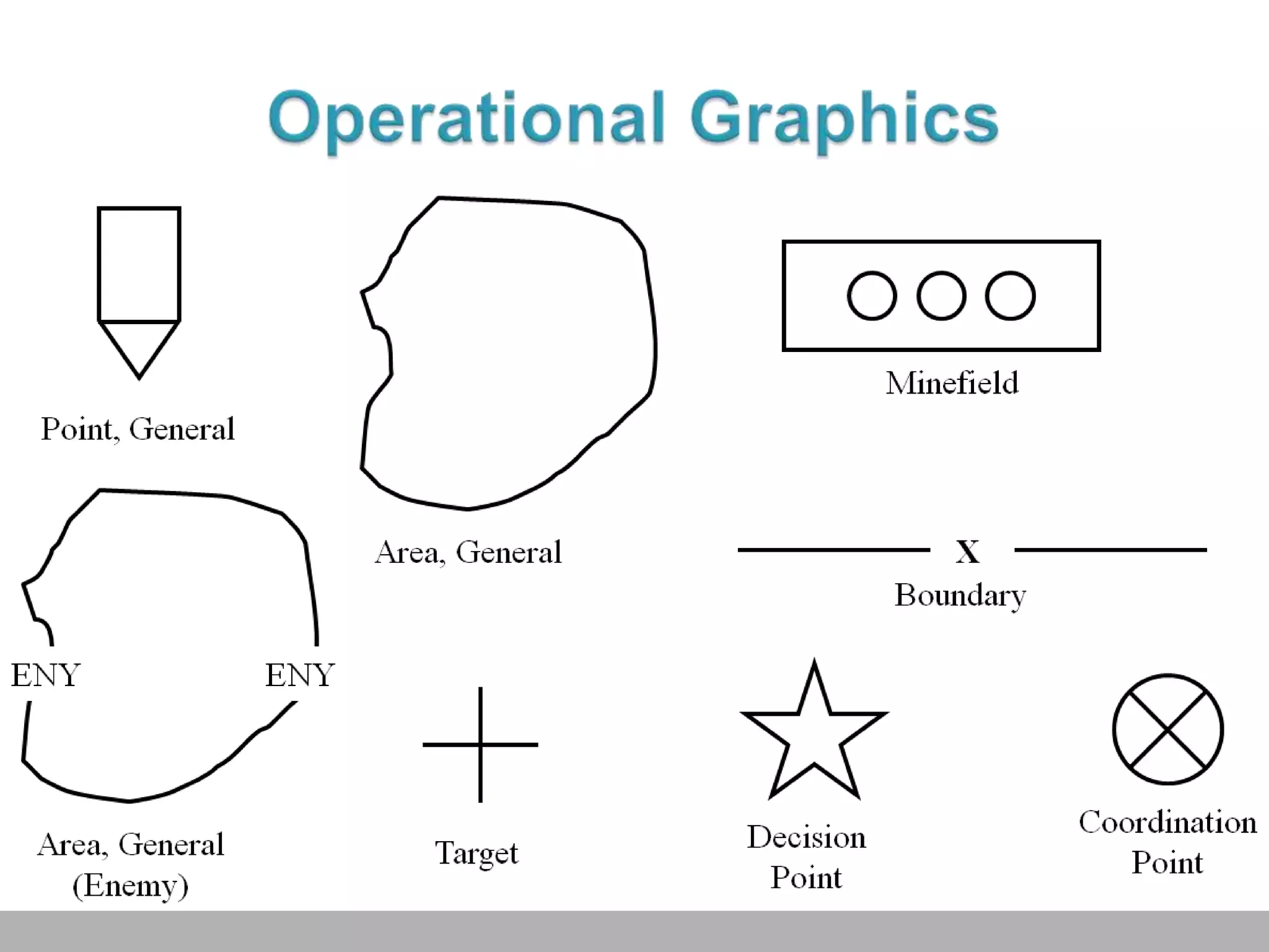
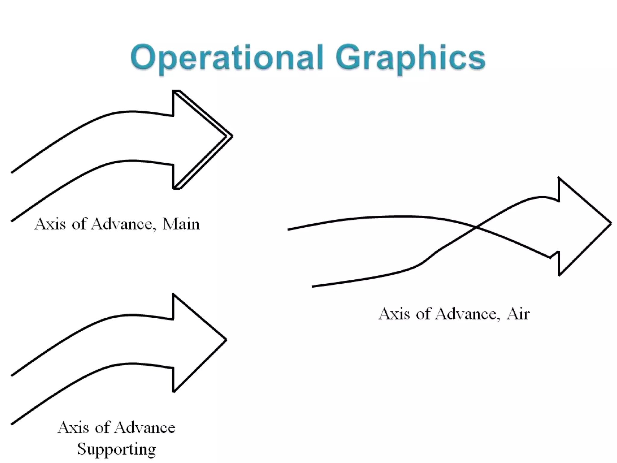
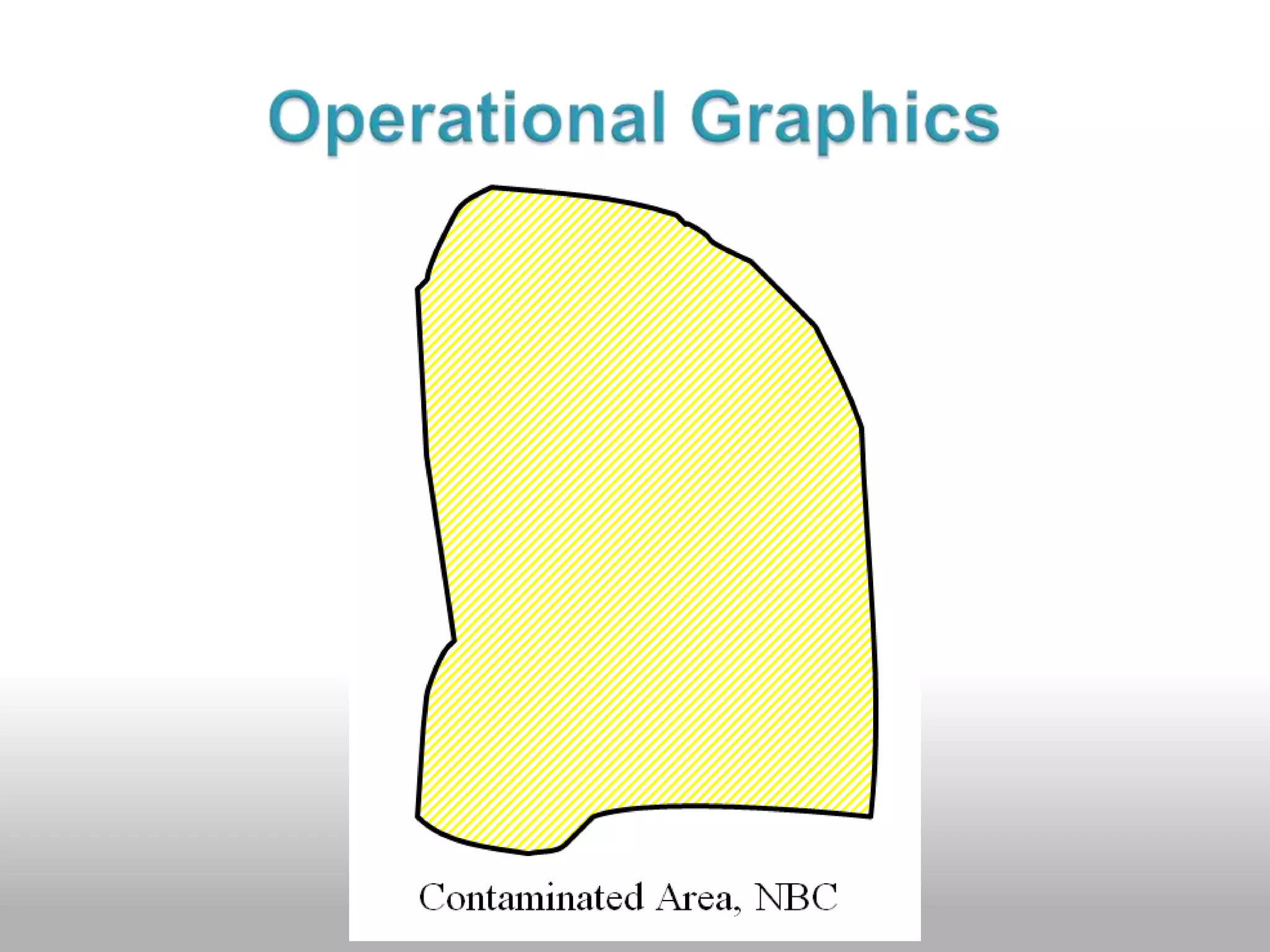
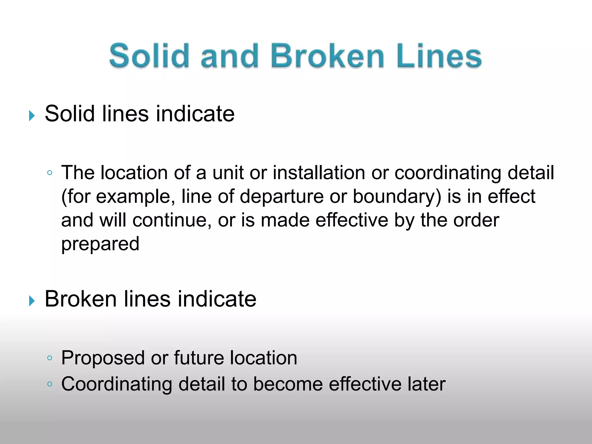
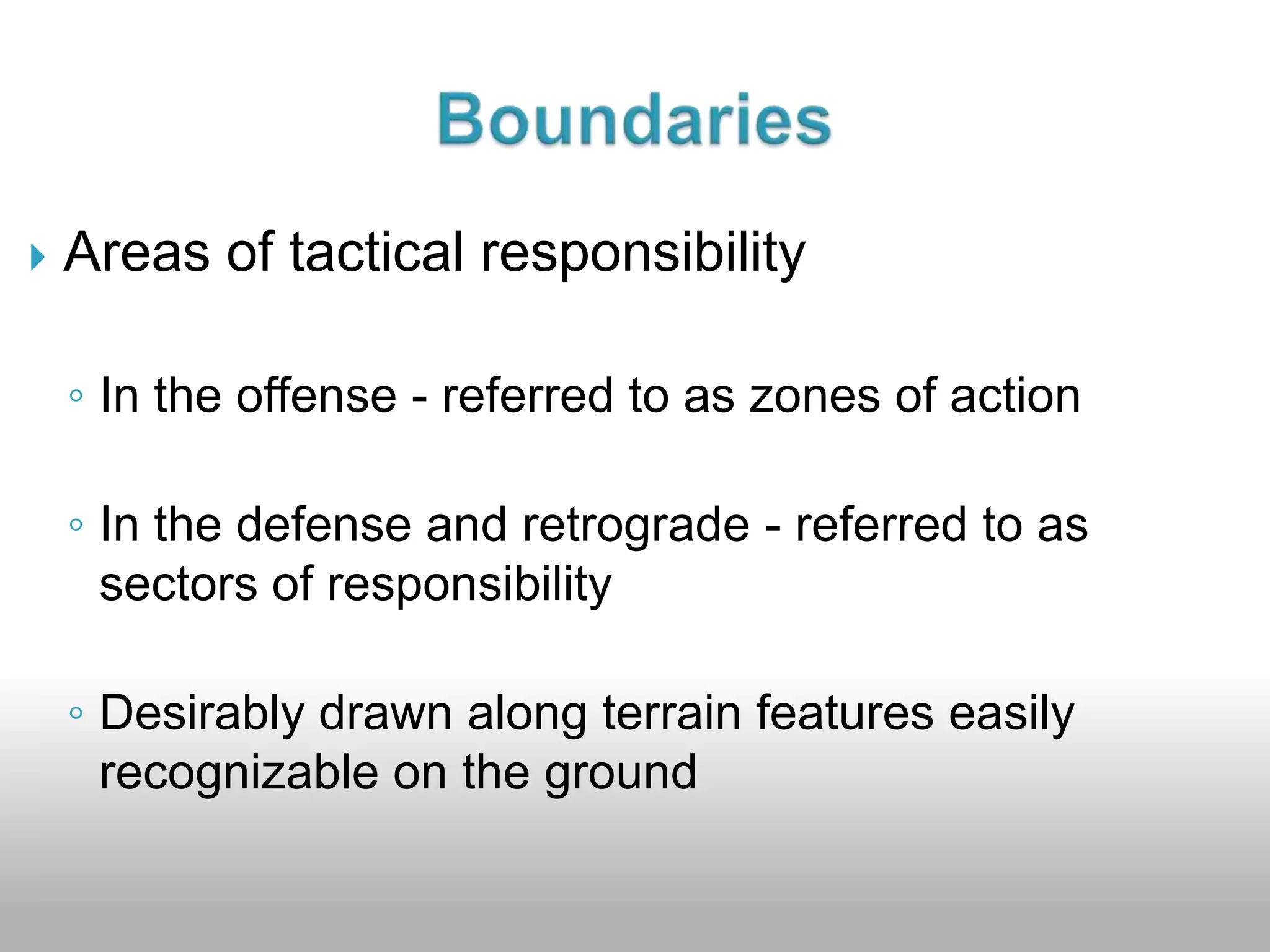
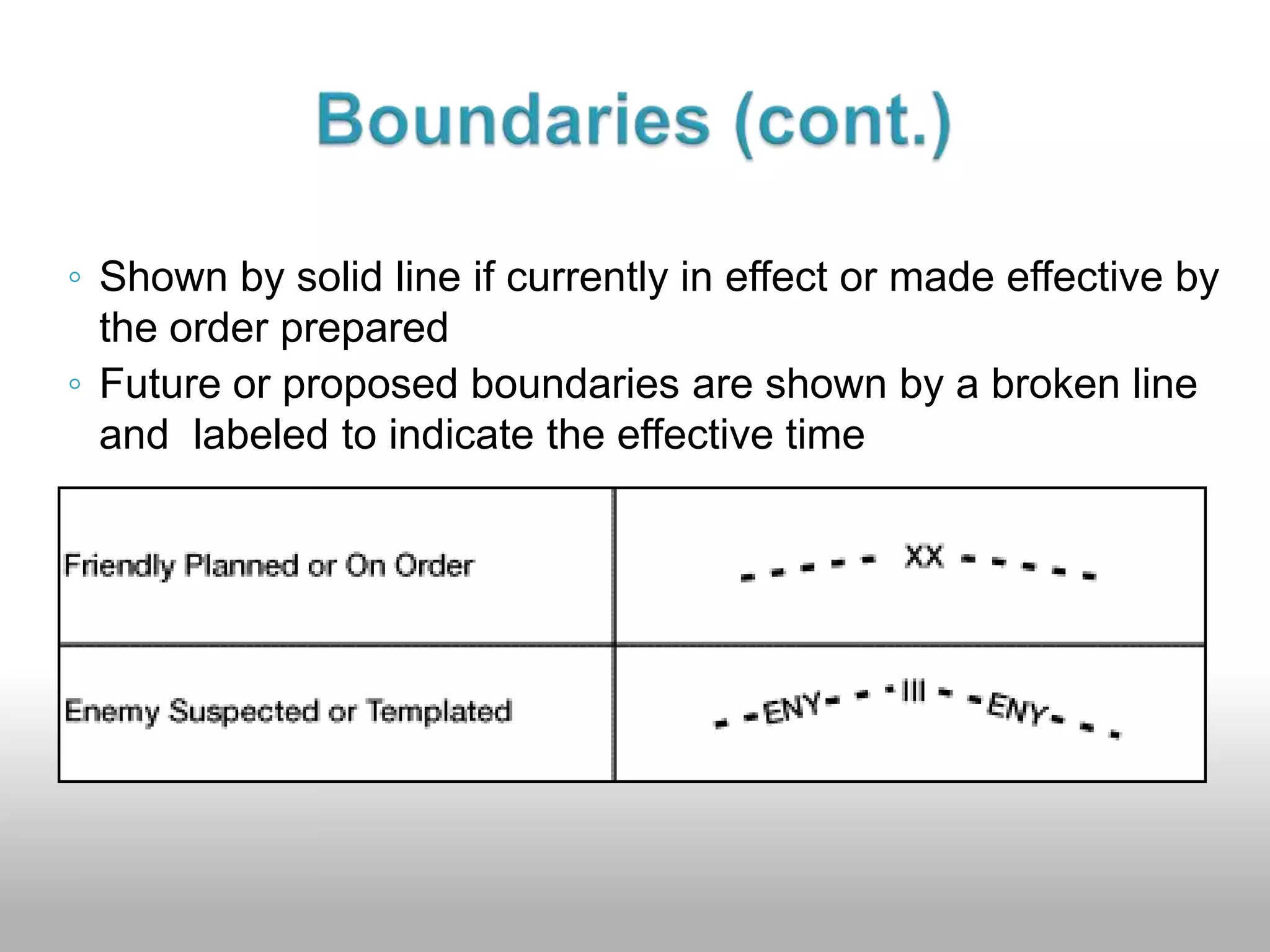
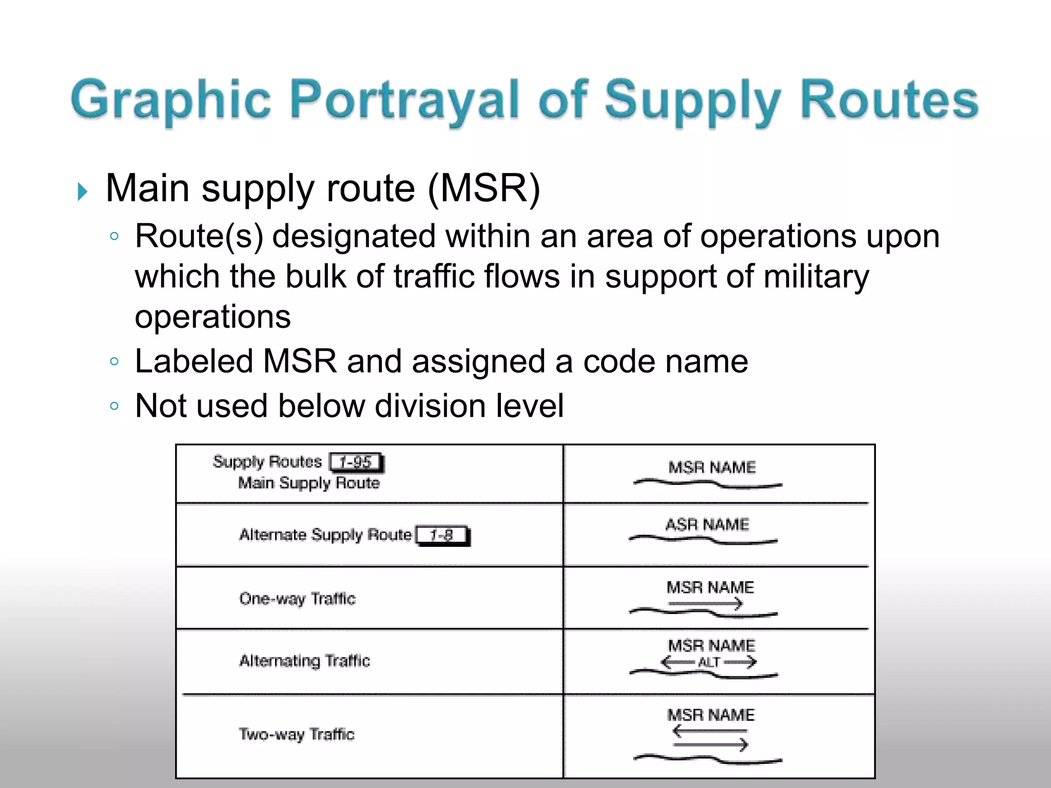
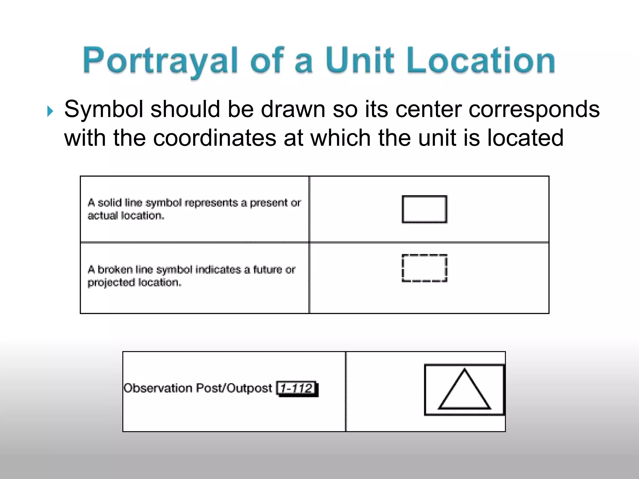
The document provides guidance on preparing an operation overlay using standard military symbols and graphics. It describes how to register and label the overlay, plot details such as unit locations and boundaries using appropriate colors, and mark the classification. Standard unit and graphic symbols are explained, including how to depict boundaries, phase lines, objectives, and other control measures.


![KOKODA: So it was at Kokoda? [Humanities]](https://cdn.slidesharecdn.com/ss_thumbnails/kokodasoitwaskokoda-130930085702-phpapp02-thumbnail.jpg?width=640&height=640&fit=bounds)


