Patent for Steamer with Wrapped Cord and Hose
•
0 likes•7 views

The patent describes a steamer device comprising a body containing a steam generation unit. The device has first and second side panels attached to the body that provide wrapping locations for storage of a power cord and steam supply hose. The wrapping locations are formed between the body and side panels and allow the cord and hose to be neatly wrapped and stored when not in use.

Recommended
More Related Content
Similar to Patent for Steamer with Wrapped Cord and Hose
Similar to Patent for Steamer with Wrapped Cord and Hose (20)
More from Mark Rosenzweig
Recently uploaded
Recently uploaded (20)
Patent for Steamer with Wrapped Cord and Hose
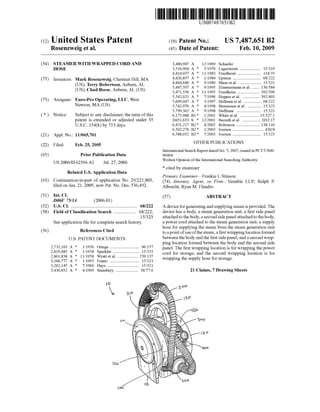
- 1. United States Patent USOO7487651B2 (12) (10) Patent No.: US 7487,651 B2 Rosenzweig et al. (45) Date of Patent: Feb. 10, 2009 (54) STEAMERWITH WRAPPED CORD AND 3,480,987. A 12/1969 Schaefer HOSE 3.510.904 A * 5/1970 Lagerstrom .................. 15,319 4.414,037 A * 1 1/1983 Friedheim .. ... 134/35 (75) Inventors: Mark Rosenzweig, Chestnut Hill, MA 3. So A 3. E.al. ---- s:sy aSee all. . ... ... ... .. . .. ... . S. GRosely, 5.447,597 A * 9/1995 Zimmermannetal. ...... 156,584 s s s 5,471,556 A * 1 1/1995 Friedheim ................... 392,399 5,542,021 A * 7/1996 Hopperetal. .... ... 392.403 (73) Assignee: Euro-Pro Operating, LLC, West 5,609,047 A * 3/1997 Hellman et al. ............... 68.222 Newton, MA (US) 5,742,976 A * 4/1998 Bensussen et al. ............ 15,323 - 5,799,362 A * 9/1998 Huffman .......... ... 15,321 (*) Notice: Subject to any disclaimer, the term ofthis 6,175,988 B1* 1/2001 White et al. ...... ... 15,327.1 patent is extended or adjusted under 35 D451,653 S * 12/2001 Berreth etal. ............... D32.17 U.S.C. 154(b) by 713 days. 6,431,217 B2 8/2002 Robinson .................... 138,110 6,502,276 B2 1/2003 Iversen .......................... 420.8 (21) Appl. No.: 11/065,701 6,588,052 B2 * 7/2003 Iversen ........................ 15,323 (22) Filed: Feb. 25, 2005 OTHER PUBLICATIONS International Search ReportdatedOct. 5, 2007, issuedin PCT/US06/ (65) Prior Publication Data O6464. US 2006/O162396 A1 Jul. 27, 2006 Written Opinion ofthe International Searching Authority. * cited by examiner Related U.S. Application Data Primary Examiner Frankie L. Stinson (63) Continuation-in-part ofapplication No. 29,221.803, (74) Attorne Agent, or Firm Venable LLP, Ralph P. filed on Jan. 21, 2005, now Pat. No. Des. 536,492. Albrecht; Ryan M. Flandro (51) Int. Cl. (57) ABSTRACT D6F 75/14 (2006.01) (52) U.S. Cl. ........................................................ 68/222 A deviceforgeneratingandsupplyingsteam isprovided.The (58) Field ofClassification Search ................... 68/222; device has a body, a steam generation unit, a first side panel 15/323 attachedtothebody,asecondsidepanelattachedtothebody, Seeapplication file forcomplete search history. a power cord attached to the steam generation unit, a Supply hose for Supplying the steam from the steam generation unit(56) References Cited U.S. PATENT DOCUMENTS 2,731,103 A 1/1956 Ortega ......................... 96.157 2,819,485 A 1/1958 Sparklin ...... ... 15,323 - - - - - 239,137 ck ck 2,861,838 A * 1 1/1958 Wyattet al. .....ck ck ck 3,166,777 A 1/1965 Frantz ......... ... 15,323 3,262,145 A 7/1966 Hays ....... ... 15,321 3,436,852 A 4, 1969 Stansbury ................... 38,776 O a toapointofuseofthesteam,afirstwrappinglocationformed between thebody andthe first sidepanel, anda secondwrap ping location formed between the body and the second side panel. The first wrapping location is forwrapping the power cord for storage, and the second wrapping location is for wrapping the Supply hose for storage. 21 Claims, 7 Drawing Sheets
- 2. US 7487,651 B2Sheet 1 of 7Feb. 10, 2009U.S. Patent FIG. 1
- 3. U.S. Patent Feb. 10, 2009 Sheet 2 of7 US 7487,651 B2
- 4. U.S. Patent Feb. 10, 2009 Sheet 3 of7 US 7487,651 B2 3od la 20 12 o 2O t S. tiss A NSSIt
- 5. U.S. Patent Feb. 10, 2009 Sheet 4 of7 US 7487,651 B2 Y S |O
- 6. U.S. Patent Feb. 10, 2009 Sheet 5 Of 7 US 7487,651 B2
- 7. U.S. Patent Feb. 10, 2009 Sheet 6 of7 US 7487,651 B2
- 8. U.S. Patent Feb. 10, 2009 Sheet 7 Of 7 US 7487,651 B2 fSr CSnasN NsNs 2 r E. re t -- e E. sa se
- 9. US 7487,651 B2 1. STEAMER WITH WRAPPED CORD AND HOSE This application is a Continuation-In-Part ofU.S. Design patent application Ser. No. 29/221,803 filed Jan. 21, 2005. BACKGROUND OF THE INVENTION 1. Field ofthe Invention The present invention relates generally to steamers. More particularly, the invention relates to portable steamers with a cord and a hose that wrap around the Steamer for storage. 2. Related Art Portable steamers used forcleaninghave become increas ingly morepopularin recentyears. Portable steamers can be battery-powered or can require plugging into an electrical outlet. Most steamers have a hose fortransporting the steam from a steam generation unit, orboiler, to the point ofuse of thesteam.Aproblemassociatedwith manyportablesteamers is storage ofthe Steam Supply hose and, ifpresent, the elec trical power cord when the steamer is not in use. BRIEF SUMMARY OF THE INVENTION The invention addresses the problem ofhow to store the steam Supply hose and the electrical power cord when the steameris notin use. This problem isaddressedbyproviding areas on the body of the steamer for wrapping the steam supply hose and the power cord around the body (or other portion ofthesteamer)toprovideaneatandeasywayto store the steam Supply hose and the power cord. Particular embodiments ofthe invention provide a device forgenerating andSupplying steam. The devicehasabody, a steam generation unit, a first side panel attachedto the body, a second side panel attached to the body, a power cord attached to the steam generation unit, a Supply hose for Sup plyingthe steam from the steam generation unit to apoint of useofthesteam,afirstwrappinglocation formedbetweenthe body andthefirstsidepanel,anda second wrapping location formed between thebodyandthe secondsidepanel.The first wrappinglocation isforwrappingthepowercord forstorage, and the second wrapping location is for wrappingthe Supply hose for storage. Other embodiments ofthe invention provide a device for generating and Supplying steam. The device has a body, a steam generation unit, a first side panel attachedto the body, a second side panel attached to the body, a power cord attached to the steam generation unit, a Supply hose for Sup plyingthe steam from the steam generation unit to apoint of use ofthesteam,afirstwrapping location formedonthebody and bounded by the first side panel, and a second wrapping location formed on thebody andboundedby the second side panel. The first wrapping location is forwrapping the power cord for storage, and the second wrapping location is for wrapping the Supply hose for storage. Otherembodiments,aswellasthestructureandfunctionof preferredembodiments willbecome apparent from aconsid eration ofthe description, drawings, and examples. BRIEF DESCRIPTION OF THE DRAWINGS The foregoing and other features and advantages of the invention will be apparent from the following, more particu lardescription ofpreferredembodiments ofthe invention, as illustrated in the accompanying drawings wherein like refer ence numbersgenerally indicate identical, functionally simi lar, and/or structurally similarelements. 5 10 15 25 30 35 40 45 50 55 60 65 2 FIG. 1 is a perspective view of an embodiment of the invention; FIG. 2 is a front view ofthe embodiment shown in FIG. 1; FIG. 3 is a rear view ofthe embodiment shown in FIG. 1; FIG. 4 is a left side view oftheembodiment shown in FIG. 1; FIG.5isarightside viewoftheembodimentshown inFIG. 1; FIG. 6 is a top view ofthe embodiment shown in FIG. 1; and FIG. 7 is a bottom view ofthe embodiment shown in FIG. 1. DETAILED DESCRIPTION OF THE INVENTION An exemplaryembodimentoftheinvention is showninthe drawingsand describedherein. The exampleofthe invention shown in thedrawings is a steamer10havinga body 100 that contains a steam generation unit, or boiler. Attached to one sideofbody 100 isa sidepanel 110havinga supportleg 112. Attached to theopposite sideofbody 100 is a side panel 120 havinga supportleg 122(bestseen in FIGS.4and5). Steamer 10 is also provided with a handle 130 to facilitate carrying steamer 10. A hose 200 is provided for directing the steam from the steam generation unit to the point ofuse ofthe steam. Hose 200is connectedto thesteamgenerationunitby wayofahose connectionport220andhas,atitsoppositeend,asteamwand 210. Steam wand 210 provides acomfortable way to grip the end ofhose 200 and direct the steam where needed. Thefiguresshowhose200beingwrappedaroundbody 100 inawrappinglocation116formedbybody 100andsidepanel 110 (best shown in FIGS. 2and3). Inalternateembodiments, wrapping location 116 is formed by the body alone and the body is configured to provide horizontal constraint for hose 200 as well as vertical constraint. A power cord 300 is provided to connect the steam gen eration unittoanelectrical outlet.A wrappinglocation 126 is formed by body 100 and side panel 120 to provide a storage locationforpowercord300. Inalternateembodiments,wrap pinglocation 126 is formedby thebody aloneandthebody is configured to provide horizontal constraint for power cord 300 as well as vertical constraint. As shown by the drawings, wrapping locations 116, 126 provide convenient and neat storage ofhose 200 and power cord 300. In this embodiment, sidepanels 110, 120andbody 100are generally circular in shape. It is noted, however, that other shapes can also be used. For example, oval or polygonal shapes can be used. Also, although Support legs 112, 122 are each shown as havinga single contactarea forcontactingthe Surface on which steamer 10 sits, it is noted that Support legs having two or more contactpoints each and/orhaving differ ent shapes can also be used. Side panels 110, 120 can be removable so that they can be replacedby sidepanelshaving different shapes orcolors. For example, side panels 110, 120 can be triangular shaped with the lower leg ofeach triangle acting as the contact point (or Supportleg). Interchangeablesidepanels may bedesirableto alter the color or shape of steamer 10 and thus its visual impact. Inthisexample, steamer10isalsoprovidedwithafillercap and pressure reliefsafety valve 400. Filler cap and pressure reliefsafety valve400 can be removed to fill steamer10 with water and, in this example, includes a pressure relief safety
- 10. US 7487,651 B2 3 valve that vents pressure to the atmosphere if the internal pressure ofthe steam generation unit rises above a predeter mined value. As shown in FIGS. 3-5, a wandholder 140 is provided on body 100 to hold steam wand 210 when not in use. The embodiments illustrated and discussed in this specifi cation are intended only to teach those skilled in the art the best way known to the inventors to make and use the inven tion. Nothing in this specification should be considered as limiting the scope ofthe invention. All examples presented are representative and non-limiting. The above-described embodiments of the invention may be modified or varied, withoutdeparting fromtheinvention, as appreciatedbythose skilled in theartin lightoftheaboveteachings. Itis therefore to be understood that the invention may be practiced other wise than as specifically described. What is claimed is: 1. A device forgenerating and Supplying steam, compris ing: a body; a steam generation unit; a first side panel attached to the body and having a first Support leg extending from its perimeter; a second side panel attached to the body and having a second Support leg extending from its perimeter; apower cord attached to the steam generation unit; a Supply hose for Supplying the steam from the steam generation unit to a point ofuse ofthe steam; a first wrapping location formed between the body and the first side panel; and a second wrapping location formed between the body and the second side panel, wherein the first wrapping location is for wrapping the power cord for storage, and the second wrapping location is for wrapping the Supply hose for storage. 2. The device ofclaim 1, wherein the first side panel is on afirstsideofthebodyandthesecondsidepanelisonasecond side ofthe body opposite to the first side. 3. The device of claim 1, wherein the first side panel is circular and the second sidepanel is circular. 4. Thedeviceofclaim 1,whereinthesteamgenerationunit is contained within the body. 5. The device ofclaim 1, wherein the body is generally circular in cross section. 6. The device of claim 1, further comprising a handle extending from the body. 7.Thedeviceofclaim 1,furthercomprisingasteam Supply wand attached to an end ofthe steam Supply hose. 8. The deviceofclaim 7, furthercomprisinga wandholder attached to thebody for securing the wand in a storage posi tion. 9. The device of claim 1, wherein the side panels are removable from the body such that the side panels are inter changeable with other side panels. 10. Thedeviceofclaim 1, wherein thefirstsidepanelison afirstsideofthebodyandthesecondsidepanelisonasecond side ofthe body opposite to the first side, the first side panel is circular, the second sidepanel is circular, and the body is generally circular in cross section. 11.A device forgenerating andSupplying steam, compris 1ng: 10 15 25 30 35 40 45 50 55 60 a body; a steam generation unit; a first side panel attached to the body and having a first Support leg extending from its perimeter, a second side panel attached to the body and having a second Support leg extending from its perimeter; a power cord attached to the steam generation unit; a Supply hose for Supplying the Steam from the steam generation unit to a point ofuse ofthe steam; a first wrapping location formed on the body and bounded by the first side panel; and a second wrapping location formed on the body and bounded by the second side panel, wherein the first wrapping location is for wrapping the power cord for storage, and the second wrapping location is for wrapping the Supply hose for storage. 12.Thedeviceofclaim 11,whereinthefirstsidepanel ison afirstsideofthebodyandthesecondsidepanelisonasecond side ofthe body opposite to the first side. 13. The device ofclaim 11, wherein the first side panel is circular, and the second side panel is circular. 14. The device ofclaim 11, wherein the steam generation unit is contained within the body. 15. The device ofclaim 11, wherein the body is generally circular in cross section. 16. The device ofclaim 11, further comprising a handle extending from thebody. 17. The device of claim 11, further comprising a steam Supply wand attached to an end ofthe Steam Supply hose. 18. The device of claim 17, further comprising a wand holderattachedto thebody forsecuringthewand inastorage position. 19. The device ofclaim 11, wherein the side panels are removable from the body such that the side panels are inter changeable with other side panels. 20.Thedeviceofclaim 11,whereinthefirstsidepanelison afirstsideofthebodyandthesecondsidepanelisonasecond side ofthe body opposite to the first side, the first side panel is circular, the second side panel is circular, and the body is generally circular in cross section. 21.A device forgenerating andSupplying steam, compris ing: a body; a steam generation unit; a first side panel attached to the body; a second side panel attached to the body; a power cord attached to the steam generation unit; a Supply hose for Supplying the Steam from the steam generation unit to a point ofuse ofthe steam; a first wrapping location formed between the body and the firstsidepanel for wrappingthe powercord for storage; and a second wrapping location formedbetween thebody and the second side panel for wrapping the Supply hose for Storage, wherein the first and second side panels are removable from thebody Suchthatthe sidepanels are interchange able with other side panels. k k k k k