1. * GB785218 (A)
Description: GB785218 (A) ? 1957-10-23
Improvements to ventilators
Description of GB785218 (A)
We, COLT VENTILATION LIMITED, a British
Company, of Surbiton, Surrey do hereby declare the invention, for
which we pray that a patent may be granted to us, and the method by
which it is to be performed, to be particularly described in and by
the
following statement:
The invention relates to a ventilator comprising one or more groups of
parallel pivoted louvres, connected for parallel movement.
It is an object of the invention to provide a ventilator of this kind
which provides a construction which is weathertight when the
ventilator is closed, and good air flow characteristics when the
ventilator is open.
According to the invention the ventilator comprises one or more groups
of adjacent louvres each of which is arcuate in crosssection and
mounted for rotation about a longitudinal axis located between its
upper and lower edges, and each of which is connected to a control
linkwork so that during adjustment all the louvres of a group are
caused to rotate through the same angle in the same rotational sense.
In this way when the ventilator is opened substantially smooth air
flow over the surfaces of the louvre is attained so that air will pass
more freely through the ventilators than in ventilators of comparable
area with straight louvres In addition more positive direction of the
air flow is ensured at an angular setting of the louvres, since the
air flow is substantially undisturbed over the surfaces of each louvre
Weathertightness when closed may be ensured by forming a smooth lip at
the lower edge of each louvre, overlapping the upper edge of the
adjacent louvre.
In a preferred form the ventilator comprises a framework, parallel
pivot rods 785,218 detachably mounted in the framework and each louvre
is secured at each end to a mounting plate pivoted on the rod; the 45
2. mounting plates for each group of louvres are connected to a control
linkwork In this form of construction one mounting plate may carry a
stud passing through an arcuate slot in a guide plate carried by the
50 framework, the stud being provided with a nut so that the stud may
be locked at any predetermined position in the arcuate slot thus
ensuring that the louvres of the group are held at a predetermined
angular setting 55 The guide plate may conveniently engage over two
adjacent pivots and thus be held rigidly with respect to the
framework.
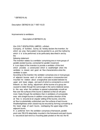
The invention is illustrated in the accompanying drawings in which: 60
Figure 1 is a front elevation taken from the interior of the space to
be ventilated, whilst Figure 2 is a side elevation partly in section
of the ventilator shown in Figure 1 65 Referring to the drawings, the
ventilator structure comprises a framework constructed as an angular
frame 1 in the sides of which are mounted parallel free pivoted rods 2
detachably secured in position by split pins 70 3 or the like Each
louvre 4 comprises a smooth slat of generally arcuate aerofoil section
swept out near its lower edge to form a lip 14 and is secured at each
end to a mounting plate 5 which is pivoted on one 75 of the rods 2
Each mounting plate is pivoted at one corner to a control link 6
whereby the mounting plates 5 and louvres 4 are caused to undergo
simultaneous parallel movement Mounted in engagement 80 with two
adjacent rods 2 is a quadrant shaped plate 7 having an arcuate slot 8
serving as a guide for a stud 9 securing one of the mounting plates 5
to the control link 6.
PATENT SPECIFICATION
Inventor:-LEONARD GORDONDAVIES.
Date of filing Complete Specification: Jan 13, 1956.
Application Date: Oct 15, 1954 No 26693154.
Complete Specification Published:: Oct 23, 1957.
Index at Acceptance Class 137, A 2 C 1.
International Classification:-F 24 Y.
COMPLETE SPECIFICATION.
Improvements to Ventilators.
785,218 The other end of the stud 9 is fitted with a wing nut 10 so
that the guide plate 7 may be gripped when the wing nut is tightened.
It will thus be appreciated that the louvre having the mounting plate
provided with a stud acts as a controlling louvre and when preset to
any position and locked there, controls the angular setting of the
remaining louvres of the group It will of course be l A appreciated
that a similar linkage may be provided at each side of the ventilator
and that a similar guide plate stud and wing nut may be provided at
each side.
The ventilator shown in Figure 2 shows in full lines the setting when
3. the ventilator is fully closed each louvre 4 having its lip 14
overlapping the top edge of the adjacent louvre and presenting an
unbroken weatherproof surface to the exterior Stops 11 are provided
for engagement over the outer edge of the top louvre and under the lip
14 at the bottom edge of the bottom louvre.
When it is desired to open the ventilator the wing nut 10 is loosened
and the control louvre moved until it takes up the desired angular
position which may, for example, be the fully opened position shown in
chain lines in Figure 2, when the control link 6 will also assume the
position shown in chain : lines in Figure 2 The wing nut 10 is then
tightened to lock the louvres 4 rigidly in position Of course it will
be appreciated that the louvres may be locked in any intermediate
position.
5) Various modifications are obviously possible Thus the ventilator
may comprise two or more groups of inter-connected louvres each of
which groun is independently adjustable so that the air stream
entering the space to be ventilated may be guided in different
directions The pivoted rods may be rotationally fixed in the side
members of the framework, the mounting plates being a frictional fit
on the pivot rods so that the-stud and guide slot are no longer
required It is also possible to fix the pivoted rods permanently in
the side members of the frame and to bolt or otherwise detachably
secure each guide to its mounting plate so that the ventilator may
still be assembled on site and any louvre may be detached without
disturbing the remaining louvres or the control link work.
* Sitemap
* Accessibility
* Legal notice
* Terms of use
* Last updated: 08.04.2015
* Worldwide Database
* 5.8.23.4; 93p
* GB785219 (A)
Description: GB785219 (A) ? 1957-10-23
Improvements in or relating to the manufacture of tuning coils for use in
circuits of radio, television and the like
4. Description of GB785219 (A)
PATENT SPECIFICATION
Date of filing Complete Specification: Sept 21, 1955.
Application Date: Sept 21, 1964 No 27297/54.
Complete Specification Published: Oct 23, 1967.
Index at Acceptance -Class 38 ( 2), T( 1 C: 7 C 1 83: 7 C 6: 11).
International Classification:-HO 2 b.
COMPLETE SPECIFICATION.
Improvements in or relating to the Manufacture of Tuning Coils for Use
in Circuits of Radio, Television and the like.
We, E K COLE LIMITED, of Ekdo Works, Priory Crescent, Southend-on-Sea,
Essex, a British Company, and ARTHUR EDWARD KING, of 2 Highfield
Close, Westcliff-on-Sea,
Essex, a British Subject, do hereby declare the invention, for which
we pray that a patent may be granted to us, and the method by which it
is to be performed, to be particularly described in and by the
following statement:-
This invention relates to the manufacture of tuning coils for use in
circuits of radio, television and the like.
Short wave coils for such circuits must usually be wound with great
accuracy so as to ensure the correct length and number of turns A
difficulty arises in securing the ends of the coil without detracting
from accurate winding This is usually effected by having a slotted
disc mounted at each end of the coil former and winding into the
anchoring slots the ends of the wire from the coils Not only is this a
relatively delicate operation but it also involves the expense of
fitting the discs which moreover have proved to be far from ideal as a
fixing means.
It has been proposed to wind a multilayer inductance coil upon a
former of thermoplastic material and to provide the coil with integral
extending ends of wire bent to a direction parallel with the axis of
the former and to embed the said ends in the wall of the former by the
application of pressure and heat In such a case, however, the embedded
ends formed no part of the coil and their position was not designed to
determine within accurate limits the exact dimensions of the coil and
hence its inductance.
One feature of the present invention is a tuning coil for use in radio
and similar lPrice 3 s 6 d l circuits, comprising a cylindrical former
of thermoplastic material on which conducting wire is wound into a
single-layer coil, the length of the coil being determined by
anchoring the ends of the coil in the material of the former by heat
5. and pressure applied at predetermined positions.
Another feature of the invention is a method of making tuning coils
for use in radio and similar circuits, in which conducting wire is
wound into a single-layer coil upon a cylindrical former of
thermoplastic material, the length of the coil being determined by
subjecting the ends of the coil to heat and pressure at predetermined
positions so that they are forced below the surface of the former and
embedded in the softened material thereof, which when cooling anchors
the ends of the coil.
A further feature of the invention is an apparatus for carrying out
the foregoing method, comprising means for mounting the coil former
and a plunger or plungers adapted to be heated and to force the ends
of the coil into the coil former.
The coil former will usually be mounted on a mandrel during the
winding operation and after winding, the ends of the coil are secured
as above stated before the coil is removed from the mandrel.
The above and other features of the invention will be apparent from
the following description and the appended claims.
The invention will be more readily understood by a perusal of the
following description of one form thereof having reference to the
drawings accompanying the Provisional Specification and in which:-
Figure 1 illustrates diagrammatically sufficient of a coil winding
machine to illustrate the modifications according to the invention;
Figure 2 is a perspective view of a coil 785,219 65.
785,219 manufactured by the machine of Figure 1; and Figure 3
illustrates in more detail a part shown in Figure 1.
, In Figure 1 a cylindrical coil former 1 of thermoplastic material is
shown mounted on a mandrel 2 which is rotated by a spur wheel 3 driven
in the usual manner A wire 4 is wound, by the usual method, on the
former 1 to form the coil shown, the convolutions being evenly spaced
apart.
When winding has been completed two heated plungers 5 are noved into
forceable contact with the ends of the coil at an exact predetermined
position, thereby determining the length of the coil Each plunger has
a sphenoidal tip for engaging the wire of the coil as shown in Figure
3.
This causes the thermoplastic material of z O the former, at the point
of engagement to soften and the ends of the coil are forced below the
normal surface of the former The plungers are then raised and on
cooling, the embedded ends of the coil are firmly -5 anchored in the
former The wire is then severed from the supply of wire carried by the
machine and the resultant coil is showvn in Figure 2 The coil and its
former may then 1 ue easily removed from the mandrel without fear olf
damage to the coil or its fixed ends.
6. It has been found possible to make coils quickly and with great
accuracy by the above method In the case of bifilar wound coils :,5
used for instance in discriminator circuits for television receivers,
the above method of manufacture has been applied with material
advantages.
* Sitemap
* Accessibility
* Legal notice
* Terms of use
* Last updated: 08.04.2015
* Worldwide Database
* 5.8.23.4; 93p
* GB785220 (A)
Description: GB785220 (A) ? 1957-10-23
Improvements in or relating to electricity supply arrangements
Description of GB785220 (A)
COMPLETE SPECIFICATION.
Improvements in or relating to Electricity Supply Arrangements.
We, E. K. COLE LIMITED of Ecko Works,
Priory Crescent, Southend;on-Sea, Essex, a
British Company, and ARTHUR EDWARD
KING, of 7 Satanita Close, Westcliffe-on-Sea,
Essex, a British Subject, do hereby declare the invention, for which
we pray that a patent may be granted to us, and the method by which it
is to be performed, to be particularly described in and by the
following statement:
This invention relates to means for supplying electricity to apparatus
mounted on a movable conveyor. The invention is in particular for use
in soak test equipment for electrical apparatus e.g. radio or
television receivers. In such soak test the apparatus is subjected to
conditions simulating those experienced in actual use of the apparatus
and it is necessary to move the apparatus on a conveyor so that each
apparatus under test enters the test system at the same point,
7. receives the same conditions of test for the same period of time, and
may be removed from the conveyor at a given position when the test is
complete.
Of course the conveyor may be adapted for more than one test system to
be operated simultaneously and spread over its length but for
simplicity we shall describe the simplest form in which the conveyor
constitutes a single system.
In such a system it is important to avoid sparking which gives rise to
electrical interference and a system with a stationary conductor
traversed by sliding electrical contacts is defective from this point
of view.
A feature of the invention is a means for supplying electricity to
apparatus on a movable conveyor, in which the supply conductors, from
which parallel connections are provided for connecting to apparatus on
the conveyor, move synchronously with the conveyor.
Another feature of the present invention is an arrangement for
supplying electricity to apparatus under test which comprises feeder
electric conductors in two continuous bands, passing about guides,
means for supplying electricity to the conductors so that they
constitute opposite terminals of an electrical supply, means for
imparting motion to the conductors about their guides, means for
moving a conveyor synchronously with said conductors and means fixed
at predetermined spacing along said conductors for supplying
electricity to apparatus carried by the conveyor.
The above and other features of the invention will be more readily
understood from a perusal of the following description having
reference to the drawing accompanying the
Provisional Specification and which is a perspective view of
sufficient to illustrate one embodiment of the invention.
In the drawing, gun metal drums 1, la are adapted to be rotated about
vertical shafts 2 and 2a, the drums 1 (and the other similar drums, if
desired) being resiliently engaged by copper carbon brushes (not
shown) bearing against their peripheries or against their horizontal
faces, as desired. A number of drums similar to 1 and la, and
similarly arranged, are used at other appropriate positions (not
shown) along the conveyor. The drums are insulated from their shafts
by suitable bushes. Two horizontally disposed endless copper bands 3
and 4 pick up current from the drums 1 around which they pass (for
example the conductors 3 and 4 may be a line and neutral on a single
phase supply). We have found that laminated bands of copper are
preferable to single bands of corresponding overall thickness, and we
have successfully used bands, 2" wide and consisting of 2 laminations
each 0.040" thick, in conjunction with guide drums of 14" diameter.
Between the conductors are fixed in spaced relation carriers 5 at the
8. extremities of which are runners 6
which ride within guide rails 7 and 8. The carriers 5 are insulated
from the copper bands from which electrical connections (not shown)
are taken to terminals 9 on the carriers. From these terminals
flexible leads
10 connect to control apparatus 11 on trays
12. Control apparatus 11 serves to determine the voltages to be
supplied to apparatus to be carried by trays 12. The trays 12 are
fixed by links 13 to a chain 14 which meshes with sprocket wheels 15
and lSa on the shafts 2 and 2a. A. similar chain 16 is fixed to the
carriers 5 and engages, and is driven by, a sprocket wheel 17 which is
also mounted on the shaft 2. Similar sprocket wheels are mounted on
the other shafts. The shaft 2 is driven by spur wheels 18 and 19 from
a suitable source of drive.
In use the apparatus to be tested will be introduced into a tray 12
and connected via control apparatus 11 and flexible leads 10 with
terminals 9 on the appropriate carrier 5. When the shaft is driven,
the tray 12 is carried by the chain 14 as shown in the drawings and
synchronously with this movement the carriers 5 and conductors 3 and 4
also move. Thus throughout its traverse through the conveyor the
equipment under test is maintained supplied with electric current from
the conductors 3 and 4. Should it be desired at any time during the
movement of the equipment in the aforesaid manner automatically to
break the electric supply this can easily be effected by having
adjacent to the apparatus means which in a given position will break
the circuit between the flexible leads 10 and the terminals 9.
Various modifications may be made in the specific arrangements
described without exceeding the scope of the invention.
What we claim is : -
1. A means for supplying electricity to apparatus on a movable
conveyor, in which the supply conductors, from which parallel
connections are provided for connecting to apparatus on the conveyor,
move synchronously with the conveyor.
2. Means according to Claim 1, wherein the supply conductors comprise
horizontally disposed continuous metal bands which in operation bear
against the peripheries of metal drums or the like which rotate about
vertical axes and to which electricity is supplied by means of
resiliently engaging contacts such as carbon brushes.
3. Means according to Claim 2, wherein
said metal bands are secured to carriers
secured to a horizontally disposed chain
engaging a plurality of sprocket wheels
mounted on vertical shafts.
4. Means according to Claim 3, wherein
9. said metal drums are mounted on the
sprocket wheel shafts.
5. Means according to Claim 3, wherein the conveyor comprises a second
chain pro
vided with dependent trays or the like, said second chain engaging
further sprocket wheels mounted on said shafts so as to move
synchronously with the first-mentioned chain.
6. Means according to Claim 3, wherein the conveyor driving means is
coupled to one of said vertical shafts.
7. Means according to Claim 5, wherein each tray is provided with
control apparatus which determines the voltages to be supplied to
apparatus carried by the conveyor.
8. An arrangement for supplying electricity to apparatus under test
which comprises feeder electric conductors in two continuous bands,
passing about guides, means for supplying electricity to the
conductors so that they constitute opposite terminals of an electrical
supply, means for imparting motion to the conductors about their
guides, means for moving a conveyor synchronously with said conductors
and means fixed at predetermined spacing along said conductors for
supplying electricity to apparatus carried by the conveyor.
9. An arrangement according to Claim 8, wherein said bands are
horizontally disposed and the guides comprise metal drums or the like
rotatable about vertical axes.
10. An arrangement according to Claim 9, wherein electricity is
supplied to said bands by means of resiliently engaging contacts, such
as carbon brushes, which bear against said metal drums.
11. An arrangement according to Claim 9, wherein said drums are
mounted on vertical shafts which also carry sprocket wheels engaging a
chain to which are secured carriers secured to said bands, and driving
means being coupled to one of said shafts, whereby said conductors are
movable about said guide drums.
12. An arrangement according to Claim 11, wherein the means for moving
the conveyor synchronously with said conductors comprises a second
chain forming part of the conveyor and engaging further sprocket
wheels mounted on said shafts.
13. An arrangement according to Claim 17, wherein said conveyor
comprises a plurality of trays or the like dependent from said second
chain and spaced therealong in positions appropriate to the said
electricity supply means fixed along the said conductors.
14. Means for supplying electri^ity to apparatus on a movable
conveyor, substantiallv as herein described with reference to the
drawings accompanying the Provisional
Specification.
10. * GB785221 (A)
Description: GB785221 (A) ? 1957-10-23
Improvements relating to buckles for belts for personal wear
Description of GB785221 (A)
PATENT SPECIFICATION
Inventor:-HERBERT HOWARD WOOD.
Dale of filing Complete Specification: Nov 18, 1955.
Aplicati 1 on Date: Nov 29, 1954 No 34463154.
Costmplete Specification Published: Oct 23, 1957.
Index at Acceptance -lass 43, Al.
international Classification:-A 44 b.
COMPLETE SPECIFICATION.
Improvements relating to Buckles for Belts for Personal Wear.
We, THOMAS WALKER L Iuvr ED, a British Company, of St Paul's Square,
Birmingham 3, do hereby declare the invention, for which we pray that
a patent may be granted to us, and the method by which it is to be
performed, to be particularly described in and by the following
statement:-
This invention relates to buckles for belts for personal wear, such
buckles being of that kind which have a fixed prong or projection
(instead of a hinged prong) adapted to engage a hole in the free end
of the belt, the said buckle having an end bar, to which the fixed end
of the belt can be secured, and a transverse plate spaced from the
said end bar and carrying the aforesaid fixed prong or projection.
The object of the present invention is to provide a fixed-prong buckle
of the above kind of an improved construction.
According to the invention, a buckle for a belt for personal wear
consists of a frame having a pair of side bars joined together at one
end by an end bar, for the attachment of a fixed end of a belt, and
carrying between their opposite ends a plate spaced from the said end
bar and from which plate is stamped a fixed prong or projection for
engagement with a hole in the other end of the belt, the said fixed
prong or projection being set rearwardly of the plane of the plate and
being integrally joined to the latter inwards of the plate's outer
11. periphery, at an edge of an aperture in the said plate Preferably 3.5
the prong or projection is joined to the plate at a place near to the
front edge of the aperture, that is the edge which is furthest from
the end bar of the buckle.
Figure 1 of the accompanying drawing is 410 a front elevation of a
buckle constructed in accordance with one form of the present
invention.
lPrice 3 s 6 d l Figure 2 is an end view of the buckle.
Figure 3 is a horizontal section on line III-III, Figure 1.
Figure 4 is a perspective rear view of the buckle.
Figure 5 is a horizontal section through the buckle and a portion of a
belt attached to and fastened by the said buckle.
Figure 6 is a front elevation of a modified form of buckle in
accordance with the invention, but without the cap or cover which is
subsequently applied.
Figure 7 is a horizontal section on line VII-VII, Figure 6.
Figure 8 is a front elevation of the end portion of the buckle with
the cap or cover applied.
Figure 9 is a horizontal section on line IX-IX, Figure 8.
Figure 10 is a plan of the cap.
Referring to Figures 1 to 5 of the drawing, the belt buckle therein
shown comprises a U-shaped frame having side bars 1 joined at their
rear ends by an integral end bar 2 for attachment to the fixed end 3
of the belt, as shown in Figure 5 These side bars 1 are joined at
their front ends by an integral lozenge-shaped transverse plate 4
spaced from the end bar, the said plate 4 being integrally joined at
its opposite ends to the side bars This plate is provided with a
short, fixed, integral prong 5, of cranked form, for engaging a
selected hole in the free end 6 of the belt, as shown in Figure 5, the
said prong being set rearwardly of the plane of the plate 4 and
projecting obliquely from its inner face, away from its front edge, as
shown, being stamped or punched out of the plate so as to be left
joined thereto at a place near to, but spaced inwards of, the said
front edge of the plate The punching or stamping operation for forming
the prong 7959221 6,5 785,221 is caused to remove a substantial
portion of metal on either side of the prong, so as to leave the plate
4 with a large ornamental aperture 7 of substantially elliptical or
other suitable shape, the prong projecting centrally behind the said
aperture.
The belt is fastened by passing the free end 6 behind the plate 4, so
as to engage the prong 5 with one or other of the holes in the belt,
and then passing said free end forwardly through the buckle frame, the
pull on the belt maintaining the prong in full engagement with the
hole.
12. In the modification shown in Figures 6 to 10, the buckle comprises a
U-shaped metal frame consisting of side bars 1, 1, joined by an end
bar 2, as in Figures 1 to 5, but in this modification the said end bar
2 carries a clamping plate 8 and lay-band 9, non201 adjustable end of
the belt being clamped to said plate 8 in known manner by a lever-grip
device 10 pivoted between ears 11 on the plate (see Figure 7), whilst
the forward ends of the side bars 1, 1, are joined by an integral
circular plate 12 The said plate 12 is disposed forwards of the arms
1, 1, the latter having their forward ends bent or cranked forwardly,
as shown in Figure 7, and integrally joined to the plate 12 at top and
bottom thereof The said plate 12 is provided with a short fixed
integral prong 5 stamped or pressed out of it so as to be left joined
to the plate at a place near to, but spaced inwards of, the front
peripheral edge portion of the latter The prong 5 projects obliquely
and rearwardly from the inner face of the plate, away from the said
front edge portion of the plate, and is adapted to engage a selected
adjustment hole in the free end of the belt.
In order to fasten a belt provided with the above-described buckle,
the free end of the belt is passed behind the circular plate 12 and
through the opening in the buckle frame until the selected adjustment
hole 4.5 can be engaged with the fixed prong.
The stamping or punching of the prong 5 out of the aforesaid circular
plate 12 leaves a slot 13 in the said plate, and in order to conceal
this slot, and impart a neat and attractive appearance to the buckle,
an ornamental metal cap or cover 14 is attached to the plate The said
cap or cover is of a shallow, circular dish shape, having a shallow
annular peripheral wall 15 adapted to be closed or clenched over the
peripheral edge of the plate 12, as in Figures S and 9, said wall
being gapped at top and bottom, at 16 (Figure 10) to fit over the
forwardly-bent ends of the arms 1, 1, where they join the plate.
* Sitemap
* Accessibility
* Legal notice
* Terms of use
* Last updated: 08.04.2015
* Worldwide Database
* 5.8.23.4; 93p
* GB785222 (A)
Description: GB785222 (A) ? 1957-10-23
13. New monoazo dyestuffs derived from cyanuric chloride
Description of GB785222 (A)
Translate this text into Tooltip
[75][(1)__Select language]
Translate this text into
The EPO does not accept any responsibility for the accuracy of data
and information originating from other authorities than the EPO; in
particular, the EPO does not guarantee that they are complete,
up-to-date or fit for specific purposes.
PATENT SPECIFICATION -
Inventor: WILLIAM ELLIOT STEPHEN Date of filing Complete
Specification: Nov 14, 1955.
Application Date: Nov 29, 1954.
No 34499/54.
Complete Specification Published: Oct 23, 1957.
ERRATUM SPECIFICATION No 785,222
Page 8, line 36, after " boiling " insert " solution " THE PATENT
OFFICE, 23rd June, 1958.
stu me prc losi I 209,-/zi tnere Is aescrinea rne m Ianulacure ui azo
dyestuffs by synthesising dyestuffs containing one or more cyanuric
nuclei, ( 1) by uniting together or with other suitable components by
reaction which lead to the formation of azo dyestuffs, intermediate
products containing one or more cyanuric nuclei, or ( 2) by uniting
azo dyestuffs containing appropriate groupings, either to each other
or to other complexes, radicals or suitable residues by reaction with
the halogen of cyanuric halides.
In the said Specification there are disclosed monoazo dyestuffs,
wherein there are attached to the triazine ring two chlorine atoms and
which are obtained by reaction of one molecular proportion of an
aminonaphthol sulphonic acid with one molecular proportion of cyanuric
chloride and subsequently treating the product with a diazo compound
obtained by diazotising for example aniline, p-toluidine or
p-aminoacetanilide There are also disclosed monoazo dyestuffs, wherein
there are attached to the triazine ring one chlorine atom and one
anilino group, and which are obtained by reaction of one molecular
proportion of an aminonaphthol sulphonic acid and one molecular
proportion of aniline with one molecular proportion of cyanuric
14. chloride and subsequently treating the product with a diazo compound
obtained by diazotising a substitution product of aniline having a
negative substituent for example Cl, COTI or SO 3 H.
Adw 1 virbc LLZLU uy UIC IU Ll Udllt ul V Ql U)l UW, have superior
tinctorial value and superior fastness to wet treatments, as compared
with monoazo dyestuffs of comparable shade specifically described in
United Kingdom Specification No 209723 containing only 1 chlorine atom
attached to the triazine ring and superior fastness to light as
compared with monoazo dyestuffs of comparable shade specifically
described in United Kingdom Specification No.
209,723 which contain two chlorine atoms attached to the triazine ring
but which do not contain the ortho-sulphophenylazo substituent, when
the dyestuffs are applied to cellulosic textile materials by a process
which comprises impregnating the said textile materials with the
dyestuff in aqueous solution and subsequently subjecting the textile
material to the action of an acid-binding agent in aqueous medium for
a short period of time of the order only of a few minutes,
advantageously in the presence of an electrolyte such as sodium
chloride or sodium sulphate.
According to our invention we provide new monoazo dyestuffs which in
the form of their free acids are of the formula P 03 H H /_/ Cl A > 5
N Y C I 785,222 Index a Interna L b; he pi th be inl PATENT
SPECIFICATION
Inventor: WILLIAM ELLIOT STEPHEN Date of filing Complete
Specification: Nov 14, 1955.
Application Date: Nov 29, 1954.
No 34499/54.
Complete Specification Published: Oct 23, 1957.
Index at acceptance:-Class 2 ( 4), G, P 1 (A 3: F 4), P 9 A 3 A 4.
International Classification:-CO 9 b.
COMPLETE SPECIFICATION
New Monoazo Dyestuffs Derived from Cyanuric Chloride We, IMPERIAL
CHEMICAL INDUSTRIES LIMITED, of Imperial Chemical House, Millbank,
London, S W 1, a British Company, do hereby declare the invention, for
which we pray that a patent may be granted to us, and the method by
which it is to be performed, to be particularly described in and by
the following statement: -
This invention relates to new monoazo dyestuffs and more particularly
it relates to new monoazo dyestuffs which are valuable for the
production of fast red colourations on cellulosic materials.
In United Kingdom Specification No.
209,723 there is described ithe manufacture of azo dyestuffs by
synthesising dyestuffs containing one or more cyanuric nuclei, ( 1) by
uniting together or with other suitable components by reaction which
15. lead to the formation of azo dyestuffs, intermediate products
containing one or more cyanuric nuclei, or ( 2) by uniting azo
dyestuffs containing appropriate groupings, either to each other or to
other complexes, radicals or suitable residues by reaction with 'the
halogen of cyanuric halides.
In the said Specification there are disclosed monoazo dyestuffs,
wherein there are attached to the triazine ring two chlorine atoms and
which are obtained by reaction of one molecular proportion of an
aminonaphthol sulphonic acid with one molecular proportion of cyanuric
chloride and subsequently treating the product with a diazo compound
obtained by diazotising for example aniline, p-toluidine or
p-aminoacetanilide There are also disclosed monoazo dyestuffs, wherein
there are attached to the triazine ring one chlorine atom and one
anilino group, and which are obtained by reaction of one molecular
proportion of an aminonaphthol sulphonic acid and one molecular
proportion of aniline with one molecular proportion of cyanuric
chloride and subsequently treating the product with a diazo compound
obtained by diazotising a substitution product of aniline having a
negative substituent for example Cl, COHor SO 3 H.
There are no compounds disclosed in the said specification, however,
which contain attached to the triazine ring, in addition to two atoms
of chlorine, the residue of an aminonaphthol sulphonic acid coupling
component to which is attached the residue of a diazo component of the
benzene series which contains sulphonic acid groups.
We have found that certain monoazo dyestuffs of the kind containing
two chlorine atoms attached to the triazine ring and also an
aminonaphthol sulphonic acid radical containing an ortho,
sulphophenylazo substituent, which dyestuffs in their free acid form
are represented by the formula given below, have superior tinctorial
value and superior fastness to wet treatments, as compared with
monoazoi dyestuffs of comparable shade specifically described in
United Kingdom Specification No 209723 containing only 1 chlorine atom
attached to the triazine ring and superior fastness to light as
compared with monoazo dyestuffs of comparable shade specifically
described in United Kingdom Specification No.
209,723 which contain two chlorine atoms attached to the triazine ring
but which do not contain the ortho-sulphophenylazo substituent, when
ithe dyestuffs are applied to, cellulosic textile materials by a
process which comprises impregnating the said (textile materials with
the dyestuff in aqueous solution and subsequently subjecting the
textile material to the action of an acid-binding agent in aqueous
medium for a short period of time of the order only of a few minutes,
advantageously in the presence of an electrolyte such ias sodium
chloride or sodium sulphate.
16. According to our invention we provide new monoazo dyestuffs which in
the form of their free acids are of the formula PO 03 H ?H NH C A NN =
HS 785,222 7.5 wherein the benzene nucleus A optionally bears further
substituents other than hydroxyl and amino groups, X stands for a
hydrogen atom or a substituent other than halogen, and wherein Y 1 and
Ye iare such that one of Y 1 and Y, stands for a hydrogen atom and the
other stands for a hydrogen atom or the group -SOH.
According to our invention we also provide a process for the
manufacture of the said new monoazo dyestuffs which comprises
diazotising a primary aromatic amine of the formula: wherein X has the
meaning stated above and (the benzene nucleus may optionally bear
further substituents other than hydroxy and amino groups, and coupling
the diazo compound lthus formed with a coupling component of the
formula: c l OH NH C C l wherein Y, and Y have the meaning stated
above.
As examples of primary aromatic amines which may be used in the
process of our invention there may be mentioned aniline-2sulphonic
acid, aniline-2:5-disulphonic-acid, 3-aminobenzotrifluoride 4
sulphonic acid,2:4-dimethylaniline 6 sulphonic acid,
4chloro-5-methylaniline 2 sulphonic acid, 5chloro 4
methylaniline-2-sulphonic acid, 3acetylaminoaniline-6-sulphonic acid,
4-acetylaminoanilin e-2-sulphonic acid, 4-chloroaniline2-sulphonic
acid, 3:4 dichloroaniline-6-sulphonic acid,
4-methylaniline-2-sulphonic acid, 3-methylaniline-6-sulphonic acid,
2:4-dimethoxyaniline-6-sulphonic acid, 4-methoxyaniline2-sulphonic
acid and 5 methoxyaniline 2sulphonic acid.
As coupling components for use in the process of -our invention there
may be used for example the primary condensation products obtained by
reaction of l-amino-8-naphthol6-sulphonic acid or
1-amino-8-naphthol-3: 6disulphonic acid, or
1-amino-8-naphthol-4:6disulphonic acid, with one molecular proportion
of cyanuric chloride in aqueous medium.
According to a further feature of our invention we provide an
alternative process for the manufacture of the said new monoazo
dyestuffs which comprises reacting a monoazo compound which in the
form of its free acid is of the formula 3 H OH N N=N X H 5031 Y
wherein X, Y, and Y, have the meaning stated above and the benzene
nucleus A may optionally bear further osubstituents other than
hydroxyl and amino groups, with one molecular proportion of cyanuric
chloride The monoazo compound may conveniently be in the form of its
alkali metal salt, for example its sodium salt.
The monoazo compounds used as starting materials for reaction with
cyanuric chloride by the alternative process of the invention may be
obtained by coupling, in alkaline medium, the diazo compound obtained
17. by diazotising a primary aromatic amine, as defined above, with lan
aminonaphthol sulphonic acid of the formula wherein the Y 1 and Y have
the meanings stated above, or, alternatively, when the said diazo
compound does not contain an acylamino group, by coupling the said
diazo compound 75 with the N-acetyl derivative of the aminonaphthol
sulphonic acid and subsequently removing the acetyl group by
hydrolysis with for example caustic soda.
In the process of our invention, the diazo 80 tising of the primary
aromatic amine and the coupling of the diazo compound thus produced
wvith the coupling component are preferably carried out at a
temperature below 5 C, conveniently at a temperature between O and 85
C In the process of our invention wherein there is used a coupling
component containing the cyanuric nucleus it is advantageous to use
for the coupling reaction the said coupling componente prepared in
situ at temperatures 90 between Oland 5 C by methods known from the
literature and to carry out the couplings at similar temperatures and
at as low a p H as is possible for efficient coupling, in order that
side reactions, for example hydrolysis of the 95 chlorine atoms
remaining attached to the triazine ring, are minimized.
In the manufacture of the new dyestuffs of the invention by the
alternative process, namely by reacting equimolecular proportions 100
of a monoazo compound of the formula stated and cyanuric chloride, the
reaction is preferably carried out in aqueous medium at temperatures
between O and 50 C.
785,222 785,222 3 Similarly, in order to avoid such side-reactions
during manufacture and storage, it is generally preferable to isolate
the new dyestuffs from the media in which they have been formed at a p
H from 6 4 to 7 8 and to dry the resultant dyestuff pastes at
relatively low temperatures, for example between 200 and 400 C.,
preferably in the presence of buffering agents suitable for
maintaining a p H value of about 6 5 Examples of such buffering agents
are mixtures of disodium hydrogen phosphate and sodium dihydrogen
phosphate or of disodium hydrogen phosphate and potassium dihydrogen
phosphate.
The new dyestuffs of this invention in the form of their alkali metal
salts are readily soluble in water and are especially suitable for the
production of level and fast red colourations on cellulosic textile
materials by continuous dyeing techniques, for example by a process
which comprises impregnating the said textile materials in aqueous
medium with the dyestuff and thereafter subjecting the textile
materials, optionally after drying, to the action of an acid binding
agent for example caustic soda, in aqueous medium advantageously
containing an electrolyte such as sodium chloride or sodium sulphate,
for a short period of time, commonly of the order only of a few
18. minutes, at temperatures lying between atmospheric temperature and the
temperature of the boiling solution and also by printing methods, for
example by a process which comprises applying to the said textile
materials a printing paste containing the dyestuff and a substance
which on heating or steaming liberates an acid binding agent, for
example sodium bicarbonate, and subsequently subjecting the textile
materials to the action of heat or steam The colourations thus
produced possess a high degree of fastness to light and to wet
treatments, especially to repeated washing.
The invention is illustrated but not limited by the following Examples
in which the parts are by weight.
EXAMPLE 1.
A solution of 18 5 parts of cyanuric chloride in 100 parts of acetone
is poured into a stirred mixture of 300 parts of water and 300 parts
of crushed ice, and 2 parts of 2 N hydrochloric acid are added To the
suspension of cyanuric chloride thus obtained there is added during 1
hour a solution of 36 3 parts of the disodium salt of
1-amino-'8-naphthol3: 6-disulphonic acid, in 160 parts of water, which
has been made faintly alkaline to Brilliant Yellow by the addition of
aqueous sodium carbonate solution, the temperature of the mixture
during and subsequent to the addition being kept below 50 C The
reaction mixture is stirred until no unchanged 1-amino8-naphthol-3:
6-disulphonic acid remains in the resulting solution.
A suspension of the diazo compound from 16.45 parts of
aniline-2-sulphonic acid, obtained by diazotising a mixture of the
aniline-2-sulphonic acid in 200 parts of water and 22 parts of
hydrochloric acid (density 1.18) at a temperature between G' and 20 C
70 with 6 55 parts of sodium nitrite is added to the mixture during 5
minutes while the temperature of the mixture is maintained between G O
and 50 C 50 Parts of sodium acetate crystals are then added during 10
75 minutes to the mixture, which is then stirred for about 20 hours at
a temperature between 00 and 40 C after which time sufficient
anhydrous sodium carbonate is added to render the aqueous medium
slightly alkaline to litmus 80 Sufficient sodium chloride to give a
concentration of 200 grams per litre is added and the mixture is
stirred for 30 minutes and then filtered The solid on the filter is
washed with % aqueous sodium chloride solution and 85 dried at 20 to
450 C The product forms a bluish-red powder which dissolves in water
to give a yellowish-red solution and in concentrated sulphuric acid to
give a reddish-violet solution 90 When applied to cellulosic fibres,
for example, cotton, by the aforesaid method of impregnation and
subsequent treatment with an acid binding agent, yellowish-red
colourations are obtained possessing very good fastness 95 to repeated
washing and good fastness to light.
19. EXAMPLE 2.
A solution of 18 5 parts of cyanuric chloride in 100 parts of acetone
is poured into a stirred mixture of 300 parts of water and 300 100
parts of crushed ice To the suspension of cyanuric chloride thus
obtained there is added at a temperature below 40 C during 1 hour a
solution in 700 parts of water of 59 7 parts of the trisodium salt of
the aminoazo compound, 105 obtained by coupling diazotised 2: 4
Ldimethylaniline-6-sulphonic acid with 1-acetylamino-8naphthol-3:
6-disulphonic acid in alkaline medium and hydrolysing the product with
caustic soda The mixture is stirred for one 110 hour at a temperature
below 40 C and then 2 N aqueous sodium carbonate solution is added
gradually during a further hour at such a rate as to maintain the
mixture slightly acid to litmus The mixture is then made slightly 115
alkaline to litmus by the addition of more 2 N aqueous sodium
carbonate solution Sufficient sodium chloride to give a concentration
of 200 grams per litre is added and the mixture is stirred for 30
minutes and then filtered The 120 solid on the filter is then washed
with 20 % aqueous sodium chloride solution and dried at a temperature
between 20 and 450 C The product forms a bluish-red powder which
dissolves in water to give a red solution and 125 in concentrated
sulphuric acid to give a redviolet solution.
EXAMPLE 3.
An alternative method for the preparation of the dyestuff of Example 1
is as follows: 4 7 g 5,222 A solution of 18 5 parts of cyanuric
chloride in 100 parts of acetone is poured into a stirred mixture of
300 parts of water and 300 parts of crushed ice During 40 minutes
there is added to the suspension so formed a solution of 56 9 parts of
the trisodium salt of the aminoazo compound formed by coupling
orthanilic acid with 1-acetylamino-8-naphthol3: 6-disulphonic acid in
the presence of sodium carbonate and hydrolysing the product in
aqueous solution by means of caustic soda The mixture is stirred at a
temperature between 0 and 50 C for 30 minutes and then sodium
carbonate solution is added to it gradually until the solution formed
reacts alkaline to litmus paper Sufficient salt to give a
concentration of 200 grams per litre is then added and then an aqueous
solution containing 7 parts of anhydrous disodium hydrogen phosphate
and 12 5 parts of anhydrous potassium dihydrogen phosphate is added
and the mixture is stirred for 2 hours and then filtered The solid is
mixed intimately with 4 parts of anhydrous disodium hydrogen phosphate
and 7 2 parts of anhydrous potassium dihydrogen phosphate and dried at
40 -C.
EXAMPLE 4.
This Example describes an alternative method for the manufacture of
the dyestuff described in Example 1 The procedure of Example 1 is
20. carried out up to and including the addition of the suspension of the
diazo compound of aniline-2-sulphonic acid to the solution containing
the N-dichlorocyanuryl-lamino-8-naphthol-3: 6-disulphonic acid Then
there is gradually added to the stirred mixture, while keeping the
temperature between 00 and C, sufficient soda ash to render the
mixture only slightly acid to Congo Red paper.
Sufficient sodium chloride is then added to give a concentration of
200 grams per litre and the mixture is stirred for 30 minutes, after
which time the gradual addition of soda ash is resumed until the p H
of the mixture is between 6 and 7 as indicated by Universal Indicator
paper, and afterwards in sufficient quantity as required to maintain a
p H of 6-7 for 1 hour At the end of this period more soda ash is added
to make the mixture alkaline to glazed red litmus paper and maintain
it so until all the diazo component has reacted A solution of 7 parts
of anhydrous disodium hydrogen phosphate and 12 5 parts of anhydrous
potassium dihydrogen phosphate in parts of water is then added and the
mixture is stirred for a further 30 minutes while keeping the
temperature at 00 to 40 C, and then filtered The solid is washed with
a % aqueous solution of sodium chloride, mixed with 4 parts of
anhydrous disodium hydrogen phosphate and 7 2 parts of anhydrous
potassium dihydrogen phosphate, and then dried at 20-45 C In the
following Table are listed derivatives of aniline-2-sulphonic acid
which in equivalent amount can be substituted for it as diazo
components in the method of the above Example Also listed in the Table
are the shades of the dyeings obtained on cotton when the
corresponding products are applied from aqueous solutions by padding
and after-treating, optionally after drying, the padded material with
brine solution containing caustic soda at varying temperatures In all
cases these dyeings show very good fastness to severe washing and to
soda boiling.
Diazo component coupled with N-dichlorocyanuryl-l-amino-8naphthol-3:
6-disulphonic acid 4-Chloro-5-methyl-2-aminobenzene-sulphonic a
4-toluidine-3-sulphonic acid
5-chloro-4-methyl-2-aminobenzene-sulphonic a
4-chloroaniline-2-sulphonic acid aniline-2: 5-disulphonic acid
3-aminobenzotrifluoride-4-sulphonic acid 3:
4-dichloroaniline-6-sulphonic acid 3-aminoanisole-4-sulphonic acid
EXAMPLE 4.
A solution of 18 5 parts of cyanuric chloride in 100 parts of acetone
is poured into a stirred mixture of 300 parts of water and 300 parts
of crushed ice and 2 parts of 2 N hydrochloric acid are added There is
then added to the suspension of cyanuric chloride during 50 minutes, a
solution of 36 3 parts of the disodium salt of 1-amino-8-naphthol-4:
6disulphonic acid in 250 parts of water which has been made faintly
21. alkaline to Brilliant Shade of dyeings on cotton Red Bluish red Bluish
red Red Very yellowish red Very yellowish red Bluish red Red Yellow by
the addition of sodium carbonate solution, the temperature of the
mixture during and subsequent to the additions being 100 kept below 50
C The reaction mixture is stirred until no unchanged
1-amino-8naphthol-4: 6-disulphonic acid remains in the resulting
solution A suspension of the diazo compound from 16 45 parts of
aniline-2 105 sulphonic acid prepared by diazotising a mixture of the
aniline-2-sulphonic acid in 200 parts of water and 18 parts of
hydrochloric 785,222 and bluish red solutions respectively and gives
yellowish red colourations on cellulosic materials for example cotton
when applied thereto by padding with an aqueous solution and after
treating the padded material with a brine solution containing caustic
soda The colourations obtained lose little depth when submitted to
severe washing or soda boiling.
In place of the 16 45 parts of aniline-2sulphonic acid used as diazo
component in this Example the compounds tabulated below may be
substituted for it in equivalent amounts and the dyestuffs then
obtained give when applied to cellulosic materials colourations having
the shades indicated below and very good resistance to severe washing
and to soda boiling.
acid (density 1 18) by means of 6 55 parts of sodium nitrite keeping
the temperature between 00 and 20 C is then added to the resulting
solution formed as above The ensuing procedure involving the gradual
addition of sodium carbonate and the addition of salt to the coupling
mixture and ultimately of a mixture of sodium dihydrogen phosphate and
potassium dihydrogen phosphate dissolved in water after the coupling
reaction is completed is the same as described in Example 4 After
filtering off the dyestuff the filter cake is mixed with 4 parts of
anhydrous disodium hydrogen phosphate and 7 2 parts of anhydrous
potassium dihydrogen phosphate and dried at to 400 C The product
dissolves in water and in sulphuric acid to give yellowish red Diazo
component coupled with l-(dichlorocyanurylamino)-8naphthol-4:
6-disulphonic acid 4-Toluidine-3-sulphonic acid
4-chloroaniline-2-sulphonic acid 3-aminobenzotrifluoride-4-sulphonic
acid -
* Sitemap
* Accessibility
* Legal notice
* Terms of use
* Last updated: 08.04.2015
* Worldwide Database
* 5.8.23.4; 93p