SlideShare a Scribd company logo
1 of 8
Download to read offline
US007946306B2
(12) Ulllted States Patent (10) Patent N0.: US 7,946,306 B2
Ampoyo (45) Date of Patent: May 24, 2011
(54) PORTABLE GARAGE 5,241,977 A * 9/1993 Flores et a1. ............. .. 135/8806
D362,729 S 9/1995 Kitchel
- 5,558,261 A * 9/1996 H d ....................... .. 224/511
(76) Inventor: Geoffrey Ampoyo, Alexandrla, VA (US) 5,575,300 A 11/1996 Jasmin
_ _ _ _ _ 5,579,796 A * 12/1996 Mallo et a1. .............. .. 135/8806
( * ) Not1ce: Subject to any dlsclalmer, the term ofthis 13403382 $ 1/1999 James
patent is extended or adjusted under 35 2 i?mes
a a BISOII
U'S'C' 154(1)) by 0 days‘ 5,954,076 A 9/1999 McGinnis
6,035,874 A * 3/2000 Po-Chang ................ .. 135/88.06
(21) APP1~ NOJ 11/844,570 6,394,118 B1 * 5/2002 Cikanowick et a1. .... .. 135/8806
6,402,220 B2 6/2002 Allen
(22) Filed: Aug. 24, 2007 6,988,505 B2 1/2006 Powell et a1.
2004/0040590 A1 3/2004 Powell et al.
(65) Prior Publication Data FOREIGN PATENT DOCUMENTS
US 2008/0053505 A1 Mar. 6, 2008 W0 WO 91/18164 11/1991
W0 WO 96/13645 5/1996
Related US. Application Data * Cited by examiner
60 P " l l' t' N.60/824116 ?ld A .
( ) 3503138061121 app 10a Ion O ’ ’ e on ug Primary Examiner * David Dunn
’ ' Assistant Examiner * Noah Chandler Hawk
(51) Int_ CL (74) Attorney, Agent, or Firm * Shlesinger, Arkwright &
E04H 15/06 (2006.01) Garvey LLP
(52) US. Cl. .................................................. .. 135/88.06
(58) Field of Classi?cation Search ............. .. 135/8801, (57) ABSTRACT
135/8805, 88,06; 224/4226, 4227, 4228, A portable shelter that attaches to the outsides ofthe tires of
224/558; 248/291, 229,14, 22923, 22924, the vehicle, as opposed to the body or Wheel hubs of the
248/229_13, 231'51 vehicle. The shelter includes a canopy attached to an upper
See application ?le for complete Search history, end of at least one mast, and a mast base that is attached to a
loWer end of the mast. The mast base comprises a threaded
(56) References Cited bolt, a plate having a threaded opening for receiving the bolt
US. PATENT DOCUMENTS
2,477,051 A * 7/1949 Eisenhauer,Sr. ....... .. 152/225R
2,508,757 A 5/1950 Gray
3,036,583 A 5/1962 Miller
4,529,023 A * 7/1985 Deland ................... .. 152/225R
4,605,030 A 8/1986 Johnson
4,655,236 A 4/1987 Dorame et al.
4,667,692 A 5/1987 Tury et a1.
4,944,321 A 7/1990 Moyet-Ortiz
therethrough, and a holder for receiving a loWer end of the
bolt. The base also includes a plurality ofarms that each have
a ?rst end attached to the holder and a second end attached to
a hook. Braces are mounted betWeen the plate and the arms so
that When the bolt moves relative to the plate, the arms move
relative to the holder so that the hooks on the arms can receive
the outsides of a tire.
12 Claims, 4 Drawing Sheets
4..
100
/- 130
US. Patent May 24, 2011 Sheet 1 014 US 7,946,306 B2
US. Patent May 24, 2011 Sheet 2 of4 US 7,946,306 B2
FIG. 4
US. Patent May 24, 2011 Sheet 3 of4 US 7,946,306 B2
US. Patent May 24, 2011 Sheet 4 of4 US 7,946,306 B2
120
40
W
130
US 7,946,306 B2
1
PORTABLE GARAGE
CROSS-REFERENCE TO RELATED
APPLICATIONS
This application claims priority to US. provisional patent
application No. 60/824,116 to Geoffrey Ampoyo ?led on
Aug. 31, 2006, entitled “Portable Garage,” the subject matter
ofWhich is herein incorporated by reference in its entirety.
BACKGROUND OF THE INVENTION
1. Field of the Invention
The present invention is directed to a portable shelter for
covering a vehicle. More speci?cally, the present invention
involves a portable garage that attaches to the outsides of a
vehicle’s tires so that the garage does not damage the body of
the vehicle or the Wheel hubs.
2. Brief Description of the Prior Art
One ofthe most desired aspects ofoWning an automobile is
having your oWn garage. People tend to park under a shade of
a tree or a shade ofa tall building during hot sunny Weather to
avoid going inside an automobile With an oven-like tempera
ture after parking for a feW hours. Also, during Winter, people
Without garages do not have a choice but to park outdoors and
expose their vehicles to the elements. These individuals have
to hope that When hail occurs, it does not damage their auto
mobiles.
Portable shelters for automobiles are Well knoWn and have
been around for some time, such as the US. Pat. No. 4,655,
236 to Dorame et al., US. Pat. No. 6,988,505 to PoWell et al.,
and US. Pat. No. 5,575,300 to James. These devices use the
ground or the center of a Wheel hub for support. As a result,
the prior art shelters can mar or otherWise damage a vehicle.
Thus, there is a need for a portable shelter that does not come
in contact With a vehicle’s surface or Wheel hub.
SUMMARY OF THE INVENTION
The present invention is directed to a portable shelter for a
vehicle that attaches to the outsides of the vehicle’s tires so
that the shelter does not contact and damage the vehicle’s
body surface or Wheel hubs. The shelter includes a canopy
attached to an upper end of at least one mast, and a mast base
that is attached to a loWer end of the mast. The mast base
comprises a threaded bolt, a plate having a threaded center
opening for receiving said bolt therethrough, and a holder for
receiving a loWer end of said bolt. The base also includes a
plurality of arms that each have a ?rst end attached to the
holder and a second end attached to a hook that is adapted to
receive an outside of a tire. Braces are mounted betWeen the
plate and the arms so that When the bolt moves relative to the
plate, the arms move relative to the holder so that the hooks on
the arms can receive the outsides of a tire.
It is an object of the invention to provide an automobile
shelter that can be easily assembled and to ?t a variety of
automobile siZes.
Another object of the invention is to provide a portable
automobile shelter With a telescoping vertical support mast
attached to a clamping mechanism that grips the outsides ofa
vehicle tire.
Still another object of the invention is to provide an auto
mobile shelter that can be adjusted to a vehicle’s height and
also independently adjustable mast for protection against the
Weather.
20
25
30
40
45
50
55
60
65
2
Still another object of the invention is to provide an auto
mobile shelter that does not come into contact With a vehicle
body.
Another object ofthe invention is to provide an automobile
shelter having a ?exible fabric cover With a frame secured by
a latch to the masts.
These advantages and other features of the invention Will
become apparent upon studying the illustrations and descrip
tions of the embodiment of the invention.
BRIEF DESCRIPTION OF THE DRAWINGS
A better understanding of the invention Will be had With
respect to the accompanying draWings Wherein:
FIG. 1 is a right side perspective vieW ofa portable garage
in accordance With the present invention;
FIG. 2 is a perspective vieW ofa mast-clamping base ofthe
invention;
FIG. 3 is a perspective vieW of a U-shaped element ofthe
invention;
FIG. 4 is a front perspective vieW of an automobile shel
tered by the portable shelter ofthe present invention;
FIG. 5 is a front plan vieW of the sheltered automobile of
FIG. 4;
FIG. 6 is a front plan vieW ofthe mast clamping mechanism
attached to a tire; and
FIG. 7 is a front perspective vieW shoWing the inner tubing
received Within the outer tubing of the mast of the present
invention.
DETAILED DESCRIPTION OF THE PREFERRED
EMBODIMENT
As shoWn in FIGS, 1, 4, and 5, a portable canopy 10 is
attached to a U-shaped element 40 ofan inner tubing mast 35.
The U-shaped element 40 serves as a clamping means so that
the canopy frame 10 may be moved Within the slot of the
U-shaped element 40 to adjust the position of the canopy 10
relative to an automobile 20 to assure exact coverage of the
automobile 20.
The canopy frame 10 is preferably a rectangular shape that
is bent into an inverted V-shape. The frame 10 consists of
adjustable interconnected tubes and three sub frame compo
nents 32, 33, and 34. The interconnected tubes 31 are con
nectedto each otherby a threaded bolt on one end ofeach tube
and a threadednut onthe other end ofeach tube. Alternatively,
the interconnected tubes are telescoping tubes. Each of the
three sub frame components 32, 33 and 34 are connected by
?tting means, such as a T-?tting and L-?ttings. A canopy
fabric covers the entire frame 10, and the fabric is secured to
the frame 10 by securing means, such as tie doWns or Vel
cro®. The canopy fabric can be replacedWith a ?exible screen
type fabric for use on high Wind areas.
FIG. 3 shoWs the U-shaped element 40 having a latch 120
and hinges to clamp and lock the canopy frame 10. The inner
tubing mast 35 is attached to the U-shaped element 40. The
inner tubing mast 35 slides inside an outer tubing mast 30 to
adjust the height of the canopy 10. To adjust height of the
canopy 10, cotterpins are placed in aligned holes (not shoWn)
of the outer and inner masts 35 and 30, respectively, to lock
the outer and inner masts 35 and 30 in place relative to each
other. In an alternative embodiment, the outer tubing mast 30
is replaced by a height adjustable extension mast (not shoWn)
that can be planted on the ground and reinforced With ropes
and stakes to be used as a stand-alone shelter or garage.
The outer tubing mast 30 is attached to a triangular metal
plate 60 of a mast clamping base 50. As shoWn in FIG. 2, the
US 7,946,306 B2
3
outer tubing mast 30 is secured to the triangular plate 60 via
threads in the center of the triangular plate 60. In an alterna
tive embodiment, the plate 60 canhave more or less thanthree
clamping arms.
FIG. 2 shoWs the mast clamping base 50. A turning handle
140 is attached at an upper end of a threaded bolt 110, Which
screWs into the triangular metal plate 60 having threads in the
center. A loWer end of the bolt 110 mounts to a stationary
circular metal holder 112 so that the bolt 110 is able to rotate
freely Within the circular metal holder. In an alternative
embodiment, the upper end of the bolt 110 is mounted to an
unthreaded triangular metal plate 60 so that the bolt 110 is
free to rotate relative to the triangularplate 60 as the loWer end
of the bolt is screWed into a threaded circular metal holder.
The circular metal holder has three equally spaced tabs that
each receives an arm 80. The arms 80 are U-shaped in cross
section. In an alternative embodiment, the circular metal
holder 112 can have more or less than three tabs and corre
sponding arms 80.
An upper end of a rectangular metal brace 70 is pivotally
mounted to a loWer edge ofthe triangular metal plate 60, and
a loWer end ofthe brace 70 is pivotally mountedto a U-shaped
arm 80. As the bolt 110 is screWed into or out ofthe triangular
metal plate 60, the in-and-out motion ofthe bolt 110 relative
the triangular metal plate 60 causes the upper end of the
rectangular metal piece 70 to pivot about the connection to
triangular metal piece 60 and the loWer end ofthe rectangular
metal piece 70 to pivot about the connection to the U-shaped
arm 80. The pivoting movement of the rectangular metal
piece 70 causes the U-shaped arm 80 to either extend out
Wardly from the circular metal holder 112 or to move
inWardly toWard the circular metal holder 112.
A sliding rectangular metal piece 90 slides Within the slot
of each of the U-shaped arms 80. A hooking means 100 is
attached to a loWer end ofthe sliding piece 90, and the hook
ing means 100 is designed to attach to an outside of a tire. In
the preferred embodiment, the hooking means 100 is a
U-shaped hook 100. A bolt (not shoWn) is threaded through
the U-shaped hook 100 at the loWer end of the sliding rect
angular metal piece 90 With a ?at rectangular metal strip
mounted at the loWer end ofthe sliding piece 90. The bolt can
be screWed in or out to alloW adjustment for a variety oftire
Widths. A pin locks the sliding piece 90 in place relative to an
arm 80 so that the mast clamping base 50 can be siZed to
accommodate a variety oftire siZes. FIG. 6 shoWs a close up
vieW of a mast clamping mechanism attached to a tire 130.
In sum, turning the handle 140 clockWise or counterclock
Wise causes the bolt 110 to move in or out the triangular metal
plate 60 Which in turn push or pull the rectangular metal brace
70. The push or pull action ofthe rectangular metal brace 70
causes the U-shaped arm 80 to move outWardly or inWardly so
that the U-shaped hook 100 can be secured to the outside of
the automobile tire 130.
While the present invention has been described in terms of
speci?c embodiments, it is to be understood that the invention
is not limited to these disclosed embodiments. This invention
may be embodied in many different forms and should not be
construed as limited to the embodiments set forth herein;
rather, these embodiments are provided by Way ofillustration
only and so that this disclosure Will be thorough, complete
and Will fully convey the full scope of the invention to those
skilled in the art. Indeed, many modi?cations and other
embodiments of the invention Will come to mind of those
skilled in the art to Which this invention pertains, and Which
are intended to be and are covered by both this disclosure, the
draWings and the claims.
25
30
35
40
45
50
55
60
65
4
What is claimed is:
1. A portable shelter for sheltering a vehicle, comprising:
a) a canopy for sheltering the vehicle;
b) a plurality ofmasts each having a ?rst end securedto said
canopy;
c) a plurality of mast bases each secured to a respective
second end of said masts;
d) said mast bases each including a plurality ofhooks that
attach to an outside ofa tire ofthe vehicle, a bolt having
an outer end and an inner end, a plate having a threaded
opening for threadedly receiving said bolt therethrough,
a holder for rotatably receiving therein said inner end of
said bolt, a plurality of arms each having a ?rst end
attached to said holder and a second end attached to a
respective one of said hooks, and a plurality of braces
each having a ?rst end pivotally connected to said plate
and a second end pivotally connected to a respective one
of said arms;
e) said holder ofeach of said mast bases is spaced from the
tire When said mast bases are secured to the tire;
f) said plate is movable toWard said holder When said bolt
is turned one Way to cause each of said braces to push a
respective one of said arms and cause said ?rst end of
each ofsaid arms and said holder to move aWay from the
tire, Whereby said hooks are secured to the tire; and
g) said plate is movable aWay from said holder When said
bolt is turned another Way to cause each ofsaid braces to
pull a respective one ofsaid arms and cause said ?rst end
of each of said arms and said holder to move toWard the
tire, Whereby said hooks are loosened from the tire.
2. A portable shelter as in claim 1, Wherein said canopy
includes a frame bent into an inverted V-shape.
3. A portable shelter as in claim 2, Wherein said canopy
includes a fabric attached to said frame.
4. A portable shelter as in claim 3, Where said frame
includes interconnected tubes.
5.A portable shelter as in claim 1, Wherein each second end
of said masts includes a clamp for attaching to said canopy.
6. A portable shelter as in claim 5, Wherein said clamp
includes an U-shaped element.
7. A portable shelter as in claim 1, Wherein said arms are
U-shaped in cross-section.
8. A portable shelter as in claim 1, Wherein each of said
hooks includes a member adjustably attached to each of said
arms.
9. A portable shelter as in claim 1, Wherein:
a) said arms each includes a U-shaped cross-section; and
b) each of said hooks includes a member disposed Within
said U-shaped cross-section.
10. A portable shelter as in claim 1, and further comprising
a handle attached to said outer end ofsaid bolt forturning said
bolt.
11. A portable shelter as in claim 1, Wherein each of said
masts includes an inner tubing disposed Within an outer tub
ing.
12. A method of sheltering a vehicle, comprising:
a) providing a plurality of mast bases, each mast base
including a plurality ofhooks that attach to an outside of
a tire of the vehicle, a bolt having an outer end and an
inner end, a plate having a threaded opening for thread
edly receiving said bolt therethrough, a holder for rotat
ably receiving said inner end of said bolt therein, a
plurality of arms each having a ?rst end attached to said
holder and a second end attached to a respective one of
said hooks, and a plurality of braces each having a ?rst
end pivotally connected to said plate and a second end
pivotally connected to a respective one of said arms;
US 7,946,306 B2
5
b) for each of said mast bases, attaching said hooks to an
outside of a respective tire of the vehicle, turning said
bolt one Way to move said plate toWard said holder to
cause each of said braces to push a respective one ofsaid
arms and cause said ?rst end of each of said arms and
said holder to move aWay from the tire, Whereby said
hooks are secured to the tire;
6
c) providing a plurality ofmasts each having a ?rst end and
a second end;
d) for each mast, securing said mast ?rst end to a respective
one of said mast bases; and
e) securing a canopy to said second end of each of said
masts.

More Related Content

What's hot

4301 4305.output
4301 4305.output4301 4305.output
4301 4305.outputj1075017
 
Us5101215 sistem de turn telescopic
Us5101215 sistem de turn telescopicUs5101215 sistem de turn telescopic
Us5101215 sistem de turn telescopicKaterina Dumitrescu
 
4 frank a. mello - 4236654 - apparatus for blowing insulating material into...
4   frank a. mello - 4236654 - apparatus for blowing insulating material into...4   frank a. mello - 4236654 - apparatus for blowing insulating material into...
4 frank a. mello - 4236654 - apparatus for blowing insulating material into...Mello_Patent_Registry
 
4496 4500.output
4496 4500.output4496 4500.output
4496 4500.outputj1075017
 
55 daniel david dobrinski - 6303861 - connector for connecting a conductor ...
55   daniel david dobrinski - 6303861 - connector for connecting a conductor ...55   daniel david dobrinski - 6303861 - connector for connecting a conductor ...
55 daniel david dobrinski - 6303861 - connector for connecting a conductor ...Mello_Patent_Registry
 
4331 4335.output
4331 4335.output4331 4335.output
4331 4335.outputj1075017
 
4566 4570.output
4566 4570.output4566 4570.output
4566 4570.outputj1075017
 
5796 5800.output
5796 5800.output5796 5800.output
5796 5800.outputj1075017
 

What's hot (16)

780116
780116780116
780116
 
780077
780077780077
780077
 
780077
780077780077
780077
 
780077
780077780077
780077
 
4301 4305.output
4301 4305.output4301 4305.output
4301 4305.output
 
Us5101215 sistem de turn telescopic
Us5101215 sistem de turn telescopicUs5101215 sistem de turn telescopic
Us5101215 sistem de turn telescopic
 
4 frank a. mello - 4236654 - apparatus for blowing insulating material into...
4   frank a. mello - 4236654 - apparatus for blowing insulating material into...4   frank a. mello - 4236654 - apparatus for blowing insulating material into...
4 frank a. mello - 4236654 - apparatus for blowing insulating material into...
 
4496 4500.output
4496 4500.output4496 4500.output
4496 4500.output
 
55 daniel david dobrinski - 6303861 - connector for connecting a conductor ...
55   daniel david dobrinski - 6303861 - connector for connecting a conductor ...55   daniel david dobrinski - 6303861 - connector for connecting a conductor ...
55 daniel david dobrinski - 6303861 - connector for connecting a conductor ...
 
4331 4335.output
4331 4335.output4331 4335.output
4331 4335.output
 
4566 4570.output
4566 4570.output4566 4570.output
4566 4570.output
 
780087
780087780087
780087
 
780087
780087780087
780087
 
780087
780087780087
780087
 
5796 5800.output
5796 5800.output5796 5800.output
5796 5800.output
 
5796 5800.output
5796 5800.output5796 5800.output
5796 5800.output
 

Viewers also liked

Analisis pedagogica
Analisis pedagogicaAnalisis pedagogica
Analisis pedagogicainnovatic23
 
Analisis pedagogica
Analisis pedagogicaAnalisis pedagogica
Analisis pedagogicainnovatic23
 
SMAR 2012 Silver Award
SMAR 2012 Silver AwardSMAR 2012 Silver Award
SMAR 2012 Silver AwardJackie Turley
 
Un estandar para la informacion economica - financiera
Un estandar para la informacion  economica - financieraUn estandar para la informacion  economica - financiera
Un estandar para la informacion economica - financierayecamiyo
 
Process improvement in a building society
Process improvement in a building societyProcess improvement in a building society
Process improvement in a building societyTQMI
 
Why You Should Get Social
Why You Should Get SocialWhy You Should Get Social
Why You Should Get Socialjuliansteedman
 
Valores eticos y morales
Valores eticos y moralesValores eticos y morales
Valores eticos y moralesyecamiyo
 
Setya K - Observation Method of Residual Capacity Load on Pile Loading Test
Setya K - Observation Method of Residual Capacity Load on Pile Loading TestSetya K - Observation Method of Residual Capacity Load on Pile Loading Test
Setya K - Observation Method of Residual Capacity Load on Pile Loading TestSetya Kurniawan
 
72219130 sondir
72219130 sondir72219130 sondir
72219130 sondirBunz Lynch
 
Web Evaluation Tutorial:
Web Evaluation Tutorial:Web Evaluation Tutorial:
Web Evaluation Tutorial:abaker002
 

Viewers also liked (14)

Analisis pedagogica
Analisis pedagogicaAnalisis pedagogica
Analisis pedagogica
 
Analisis pedagogica
Analisis pedagogicaAnalisis pedagogica
Analisis pedagogica
 
SMAR 2012 Silver Award
SMAR 2012 Silver AwardSMAR 2012 Silver Award
SMAR 2012 Silver Award
 
Un estandar para la informacion economica - financiera
Un estandar para la informacion  economica - financieraUn estandar para la informacion  economica - financiera
Un estandar para la informacion economica - financiera
 
Process improvement in a building society
Process improvement in a building societyProcess improvement in a building society
Process improvement in a building society
 
Why You Should Get Social
Why You Should Get SocialWhy You Should Get Social
Why You Should Get Social
 
Famicuentos
FamicuentosFamicuentos
Famicuentos
 
Descubrimientos de una villa soñada
Descubrimientos de una villa soñadaDescubrimientos de una villa soñada
Descubrimientos de una villa soñada
 
Valores eticos y morales
Valores eticos y moralesValores eticos y morales
Valores eticos y morales
 
Setya K - Observation Method of Residual Capacity Load on Pile Loading Test
Setya K - Observation Method of Residual Capacity Load on Pile Loading TestSetya K - Observation Method of Residual Capacity Load on Pile Loading Test
Setya K - Observation Method of Residual Capacity Load on Pile Loading Test
 
72219130 sondir
72219130 sondir72219130 sondir
72219130 sondir
 
Resume
ResumeResume
Resume
 
CV 2015 Pavida S
CV 2015 Pavida SCV 2015 Pavida S
CV 2015 Pavida S
 
Web Evaluation Tutorial:
Web Evaluation Tutorial:Web Evaluation Tutorial:
Web Evaluation Tutorial:
 

Similar to US7946306 (7)

Similar to US7946306 (7) (20)

US8770662 (1)
US8770662 (1)US8770662 (1)
US8770662 (1)
 
US20120240757
US20120240757US20120240757
US20120240757
 
4246 4250.output
4246 4250.output4246 4250.output
4246 4250.output
 
780088
780088780088
780088
 
780088
780088780088
780088
 
780088
780088780088
780088
 
Us7487651
Us7487651Us7487651
Us7487651
 
5331 5335.output
5331 5335.output5331 5335.output
5331 5335.output
 
5331 5335.output
5331 5335.output5331 5335.output
5331 5335.output
 
US6899360
US6899360US6899360
US6899360
 
4811 4815.output
4811 4815.output4811 4815.output
4811 4815.output
 
21 gerald e. johnson - 5226522 - moving handrail guide mount with vibration...
21   gerald e. johnson - 5226522 - moving handrail guide mount with vibration...21   gerald e. johnson - 5226522 - moving handrail guide mount with vibration...
21 gerald e. johnson - 5226522 - moving handrail guide mount with vibration...
 
Us7377066
Us7377066Us7377066
Us7377066
 
4316 4320.output
4316 4320.output4316 4320.output
4316 4320.output
 
4521 4525.output
4521 4525.output4521 4525.output
4521 4525.output
 
5726 5730.output
5726 5730.output5726 5730.output
5726 5730.output
 
5726 5730.output
5726 5730.output5726 5730.output
5726 5730.output
 
US8251384 OTHER PLANET P2
US8251384 OTHER PLANET P2US8251384 OTHER PLANET P2
US8251384 OTHER PLANET P2
 
手枪击发钉击发机构
手枪击发钉击发机构手枪击发钉击发机构
手枪击发钉击发机构
 
96 100.output
96 100.output96 100.output
96 100.output
 

US7946306 (7)

  • 1. US007946306B2 (12) Ulllted States Patent (10) Patent N0.: US 7,946,306 B2 Ampoyo (45) Date of Patent: May 24, 2011 (54) PORTABLE GARAGE 5,241,977 A * 9/1993 Flores et a1. ............. .. 135/8806 D362,729 S 9/1995 Kitchel - 5,558,261 A * 9/1996 H d ....................... .. 224/511 (76) Inventor: Geoffrey Ampoyo, Alexandrla, VA (US) 5,575,300 A 11/1996 Jasmin _ _ _ _ _ 5,579,796 A * 12/1996 Mallo et a1. .............. .. 135/8806 ( * ) Not1ce: Subject to any dlsclalmer, the term ofthis 13403382 $ 1/1999 James patent is extended or adjusted under 35 2 i?mes a a BISOII U'S'C' 154(1)) by 0 days‘ 5,954,076 A 9/1999 McGinnis 6,035,874 A * 3/2000 Po-Chang ................ .. 135/88.06 (21) APP1~ NOJ 11/844,570 6,394,118 B1 * 5/2002 Cikanowick et a1. .... .. 135/8806 6,402,220 B2 6/2002 Allen (22) Filed: Aug. 24, 2007 6,988,505 B2 1/2006 Powell et a1. 2004/0040590 A1 3/2004 Powell et al. (65) Prior Publication Data FOREIGN PATENT DOCUMENTS US 2008/0053505 A1 Mar. 6, 2008 W0 WO 91/18164 11/1991 W0 WO 96/13645 5/1996 Related US. Application Data * Cited by examiner 60 P " l l' t' N.60/824116 ?ld A . ( ) 3503138061121 app 10a Ion O ’ ’ e on ug Primary Examiner * David Dunn ’ ' Assistant Examiner * Noah Chandler Hawk (51) Int_ CL (74) Attorney, Agent, or Firm * Shlesinger, Arkwright & E04H 15/06 (2006.01) Garvey LLP (52) US. Cl. .................................................. .. 135/88.06 (58) Field of Classi?cation Search ............. .. 135/8801, (57) ABSTRACT 135/8805, 88,06; 224/4226, 4227, 4228, A portable shelter that attaches to the outsides ofthe tires of 224/558; 248/291, 229,14, 22923, 22924, the vehicle, as opposed to the body or Wheel hubs of the 248/229_13, 231'51 vehicle. The shelter includes a canopy attached to an upper See application ?le for complete Search history, end of at least one mast, and a mast base that is attached to a loWer end of the mast. The mast base comprises a threaded (56) References Cited bolt, a plate having a threaded opening for receiving the bolt US. PATENT DOCUMENTS 2,477,051 A * 7/1949 Eisenhauer,Sr. ....... .. 152/225R 2,508,757 A 5/1950 Gray 3,036,583 A 5/1962 Miller 4,529,023 A * 7/1985 Deland ................... .. 152/225R 4,605,030 A 8/1986 Johnson 4,655,236 A 4/1987 Dorame et al. 4,667,692 A 5/1987 Tury et a1. 4,944,321 A 7/1990 Moyet-Ortiz therethrough, and a holder for receiving a loWer end of the bolt. The base also includes a plurality ofarms that each have a ?rst end attached to the holder and a second end attached to a hook. Braces are mounted betWeen the plate and the arms so that When the bolt moves relative to the plate, the arms move relative to the holder so that the hooks on the arms can receive the outsides of a tire. 12 Claims, 4 Drawing Sheets 4.. 100 /- 130
  • 2. US. Patent May 24, 2011 Sheet 1 014 US 7,946,306 B2
  • 3. US. Patent May 24, 2011 Sheet 2 of4 US 7,946,306 B2 FIG. 4
  • 4. US. Patent May 24, 2011 Sheet 3 of4 US 7,946,306 B2
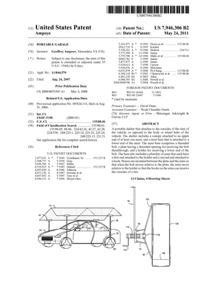
  • 5. US. Patent May 24, 2011 Sheet 4 of4 US 7,946,306 B2 120 40 W 130
  • 6. US 7,946,306 B2 1 PORTABLE GARAGE CROSS-REFERENCE TO RELATED APPLICATIONS This application claims priority to US. provisional patent application No. 60/824,116 to Geoffrey Ampoyo ?led on Aug. 31, 2006, entitled “Portable Garage,” the subject matter ofWhich is herein incorporated by reference in its entirety. BACKGROUND OF THE INVENTION 1. Field of the Invention The present invention is directed to a portable shelter for covering a vehicle. More speci?cally, the present invention involves a portable garage that attaches to the outsides of a vehicle’s tires so that the garage does not damage the body of the vehicle or the Wheel hubs. 2. Brief Description of the Prior Art One ofthe most desired aspects ofoWning an automobile is having your oWn garage. People tend to park under a shade of a tree or a shade ofa tall building during hot sunny Weather to avoid going inside an automobile With an oven-like tempera ture after parking for a feW hours. Also, during Winter, people Without garages do not have a choice but to park outdoors and expose their vehicles to the elements. These individuals have to hope that When hail occurs, it does not damage their auto mobiles. Portable shelters for automobiles are Well knoWn and have been around for some time, such as the US. Pat. No. 4,655, 236 to Dorame et al., US. Pat. No. 6,988,505 to PoWell et al., and US. Pat. No. 5,575,300 to James. These devices use the ground or the center of a Wheel hub for support. As a result, the prior art shelters can mar or otherWise damage a vehicle. Thus, there is a need for a portable shelter that does not come in contact With a vehicle’s surface or Wheel hub. SUMMARY OF THE INVENTION The present invention is directed to a portable shelter for a vehicle that attaches to the outsides of the vehicle’s tires so that the shelter does not contact and damage the vehicle’s body surface or Wheel hubs. The shelter includes a canopy attached to an upper end of at least one mast, and a mast base that is attached to a loWer end of the mast. The mast base comprises a threaded bolt, a plate having a threaded center opening for receiving said bolt therethrough, and a holder for receiving a loWer end of said bolt. The base also includes a plurality of arms that each have a ?rst end attached to the holder and a second end attached to a hook that is adapted to receive an outside of a tire. Braces are mounted betWeen the plate and the arms so that When the bolt moves relative to the plate, the arms move relative to the holder so that the hooks on the arms can receive the outsides of a tire. It is an object of the invention to provide an automobile shelter that can be easily assembled and to ?t a variety of automobile siZes. Another object of the invention is to provide a portable automobile shelter With a telescoping vertical support mast attached to a clamping mechanism that grips the outsides ofa vehicle tire. Still another object of the invention is to provide an auto mobile shelter that can be adjusted to a vehicle’s height and also independently adjustable mast for protection against the Weather. 20 25 30 40 45 50 55 60 65 2 Still another object of the invention is to provide an auto mobile shelter that does not come into contact With a vehicle body. Another object ofthe invention is to provide an automobile shelter having a ?exible fabric cover With a frame secured by a latch to the masts. These advantages and other features of the invention Will become apparent upon studying the illustrations and descrip tions of the embodiment of the invention. BRIEF DESCRIPTION OF THE DRAWINGS A better understanding of the invention Will be had With respect to the accompanying draWings Wherein: FIG. 1 is a right side perspective vieW ofa portable garage in accordance With the present invention; FIG. 2 is a perspective vieW ofa mast-clamping base ofthe invention; FIG. 3 is a perspective vieW of a U-shaped element ofthe invention; FIG. 4 is a front perspective vieW of an automobile shel tered by the portable shelter ofthe present invention; FIG. 5 is a front plan vieW of the sheltered automobile of FIG. 4; FIG. 6 is a front plan vieW ofthe mast clamping mechanism attached to a tire; and FIG. 7 is a front perspective vieW shoWing the inner tubing received Within the outer tubing of the mast of the present invention. DETAILED DESCRIPTION OF THE PREFERRED EMBODIMENT As shoWn in FIGS, 1, 4, and 5, a portable canopy 10 is attached to a U-shaped element 40 ofan inner tubing mast 35. The U-shaped element 40 serves as a clamping means so that the canopy frame 10 may be moved Within the slot of the U-shaped element 40 to adjust the position of the canopy 10 relative to an automobile 20 to assure exact coverage of the automobile 20. The canopy frame 10 is preferably a rectangular shape that is bent into an inverted V-shape. The frame 10 consists of adjustable interconnected tubes and three sub frame compo nents 32, 33, and 34. The interconnected tubes 31 are con nectedto each otherby a threaded bolt on one end ofeach tube and a threadednut onthe other end ofeach tube. Alternatively, the interconnected tubes are telescoping tubes. Each of the three sub frame components 32, 33 and 34 are connected by ?tting means, such as a T-?tting and L-?ttings. A canopy fabric covers the entire frame 10, and the fabric is secured to the frame 10 by securing means, such as tie doWns or Vel cro®. The canopy fabric can be replacedWith a ?exible screen type fabric for use on high Wind areas. FIG. 3 shoWs the U-shaped element 40 having a latch 120 and hinges to clamp and lock the canopy frame 10. The inner tubing mast 35 is attached to the U-shaped element 40. The inner tubing mast 35 slides inside an outer tubing mast 30 to adjust the height of the canopy 10. To adjust height of the canopy 10, cotterpins are placed in aligned holes (not shoWn) of the outer and inner masts 35 and 30, respectively, to lock the outer and inner masts 35 and 30 in place relative to each other. In an alternative embodiment, the outer tubing mast 30 is replaced by a height adjustable extension mast (not shoWn) that can be planted on the ground and reinforced With ropes and stakes to be used as a stand-alone shelter or garage. The outer tubing mast 30 is attached to a triangular metal plate 60 of a mast clamping base 50. As shoWn in FIG. 2, the
  • 7. US 7,946,306 B2 3 outer tubing mast 30 is secured to the triangular plate 60 via threads in the center of the triangular plate 60. In an alterna tive embodiment, the plate 60 canhave more or less thanthree clamping arms. FIG. 2 shoWs the mast clamping base 50. A turning handle 140 is attached at an upper end of a threaded bolt 110, Which screWs into the triangular metal plate 60 having threads in the center. A loWer end of the bolt 110 mounts to a stationary circular metal holder 112 so that the bolt 110 is able to rotate freely Within the circular metal holder. In an alternative embodiment, the upper end of the bolt 110 is mounted to an unthreaded triangular metal plate 60 so that the bolt 110 is free to rotate relative to the triangularplate 60 as the loWer end of the bolt is screWed into a threaded circular metal holder. The circular metal holder has three equally spaced tabs that each receives an arm 80. The arms 80 are U-shaped in cross section. In an alternative embodiment, the circular metal holder 112 can have more or less than three tabs and corre sponding arms 80. An upper end of a rectangular metal brace 70 is pivotally mounted to a loWer edge ofthe triangular metal plate 60, and a loWer end ofthe brace 70 is pivotally mountedto a U-shaped arm 80. As the bolt 110 is screWed into or out ofthe triangular metal plate 60, the in-and-out motion ofthe bolt 110 relative the triangular metal plate 60 causes the upper end of the rectangular metal piece 70 to pivot about the connection to triangular metal piece 60 and the loWer end ofthe rectangular metal piece 70 to pivot about the connection to the U-shaped arm 80. The pivoting movement of the rectangular metal piece 70 causes the U-shaped arm 80 to either extend out Wardly from the circular metal holder 112 or to move inWardly toWard the circular metal holder 112. A sliding rectangular metal piece 90 slides Within the slot of each of the U-shaped arms 80. A hooking means 100 is attached to a loWer end ofthe sliding piece 90, and the hook ing means 100 is designed to attach to an outside of a tire. In the preferred embodiment, the hooking means 100 is a U-shaped hook 100. A bolt (not shoWn) is threaded through the U-shaped hook 100 at the loWer end of the sliding rect angular metal piece 90 With a ?at rectangular metal strip mounted at the loWer end ofthe sliding piece 90. The bolt can be screWed in or out to alloW adjustment for a variety oftire Widths. A pin locks the sliding piece 90 in place relative to an arm 80 so that the mast clamping base 50 can be siZed to accommodate a variety oftire siZes. FIG. 6 shoWs a close up vieW of a mast clamping mechanism attached to a tire 130. In sum, turning the handle 140 clockWise or counterclock Wise causes the bolt 110 to move in or out the triangular metal plate 60 Which in turn push or pull the rectangular metal brace 70. The push or pull action ofthe rectangular metal brace 70 causes the U-shaped arm 80 to move outWardly or inWardly so that the U-shaped hook 100 can be secured to the outside of the automobile tire 130. While the present invention has been described in terms of speci?c embodiments, it is to be understood that the invention is not limited to these disclosed embodiments. This invention may be embodied in many different forms and should not be construed as limited to the embodiments set forth herein; rather, these embodiments are provided by Way ofillustration only and so that this disclosure Will be thorough, complete and Will fully convey the full scope of the invention to those skilled in the art. Indeed, many modi?cations and other embodiments of the invention Will come to mind of those skilled in the art to Which this invention pertains, and Which are intended to be and are covered by both this disclosure, the draWings and the claims. 25 30 35 40 45 50 55 60 65 4 What is claimed is: 1. A portable shelter for sheltering a vehicle, comprising: a) a canopy for sheltering the vehicle; b) a plurality ofmasts each having a ?rst end securedto said canopy; c) a plurality of mast bases each secured to a respective second end of said masts; d) said mast bases each including a plurality ofhooks that attach to an outside ofa tire ofthe vehicle, a bolt having an outer end and an inner end, a plate having a threaded opening for threadedly receiving said bolt therethrough, a holder for rotatably receiving therein said inner end of said bolt, a plurality of arms each having a ?rst end attached to said holder and a second end attached to a respective one of said hooks, and a plurality of braces each having a ?rst end pivotally connected to said plate and a second end pivotally connected to a respective one of said arms; e) said holder ofeach of said mast bases is spaced from the tire When said mast bases are secured to the tire; f) said plate is movable toWard said holder When said bolt is turned one Way to cause each of said braces to push a respective one of said arms and cause said ?rst end of each ofsaid arms and said holder to move aWay from the tire, Whereby said hooks are secured to the tire; and g) said plate is movable aWay from said holder When said bolt is turned another Way to cause each ofsaid braces to pull a respective one ofsaid arms and cause said ?rst end of each of said arms and said holder to move toWard the tire, Whereby said hooks are loosened from the tire. 2. A portable shelter as in claim 1, Wherein said canopy includes a frame bent into an inverted V-shape. 3. A portable shelter as in claim 2, Wherein said canopy includes a fabric attached to said frame. 4. A portable shelter as in claim 3, Where said frame includes interconnected tubes. 5.A portable shelter as in claim 1, Wherein each second end of said masts includes a clamp for attaching to said canopy. 6. A portable shelter as in claim 5, Wherein said clamp includes an U-shaped element. 7. A portable shelter as in claim 1, Wherein said arms are U-shaped in cross-section. 8. A portable shelter as in claim 1, Wherein each of said hooks includes a member adjustably attached to each of said arms. 9. A portable shelter as in claim 1, Wherein: a) said arms each includes a U-shaped cross-section; and b) each of said hooks includes a member disposed Within said U-shaped cross-section. 10. A portable shelter as in claim 1, and further comprising a handle attached to said outer end ofsaid bolt forturning said bolt. 11. A portable shelter as in claim 1, Wherein each of said masts includes an inner tubing disposed Within an outer tub ing. 12. A method of sheltering a vehicle, comprising: a) providing a plurality of mast bases, each mast base including a plurality ofhooks that attach to an outside of a tire of the vehicle, a bolt having an outer end and an inner end, a plate having a threaded opening for thread edly receiving said bolt therethrough, a holder for rotat ably receiving said inner end of said bolt therein, a plurality of arms each having a ?rst end attached to said holder and a second end attached to a respective one of said hooks, and a plurality of braces each having a ?rst end pivotally connected to said plate and a second end pivotally connected to a respective one of said arms;
  • 8. US 7,946,306 B2 5 b) for each of said mast bases, attaching said hooks to an outside of a respective tire of the vehicle, turning said bolt one Way to move said plate toWard said holder to cause each of said braces to push a respective one ofsaid arms and cause said ?rst end of each of said arms and said holder to move aWay from the tire, Whereby said hooks are secured to the tire; 6 c) providing a plurality ofmasts each having a ?rst end and a second end; d) for each mast, securing said mast ?rst end to a respective one of said mast bases; and e) securing a canopy to said second end of each of said masts.