SlideShare a Scribd company logo
1 of 14
Download to read offline
(12) United States Patent
Mello et al.
(54) ELECTRICAL SPLICE CONNECTOR
(75) Inventors: Keith F. Mello, Manchester, NH (US);
Richard Chadbourne, Merrimack, NH
(US); Daniel D. Dobrinski,
Hillsborough, NH (US)
(73) Assignee: FCI Americas Technology, Inc., Reno,
NV (US)
( *) Notice: Subject to any disclaimer, the term of this
patent is extended or adjusted under 35
U.S.C. 154(b) by 0 days.
(21) Appl. No.: 10/068,178
(22) Filed:
(65)
Feb. 6, 2002
Prior Publication Data
(51)
(52)
(58)
(56)
US 2003/0148671 A1 Aug. 7, 2003
Int. Cl? ........................... HOlR 4/50; HOlR 11/01
U.S. Cl. ........................................ 439/783; 439/863
Field of Search ................................. 439/796, 790,
439/783, 786, 863
References Cited
U.S. PATENT DOCUMENTS
414,362 A
1,657,970 A
3,205,300 A
3,384,704 A
4,066,368 A
11/1889 Anderson
1!1928 Ercole
9/1965 Becker
5/1968 Vockroth
1!1978 Mastalski et a!. ........... 403/211
10
'-.....
111111 1111111111111111111111111111111111111111111111111111111111111
GB
US006773311B2
(10) Patent No.:
(45) Date of Patent:
US 6,773,311 B2
Aug. 10,2004
4,362,352 A 12/1982 Hawkins eta!. ............ 339/248
4,428,100 A 1!1984 Apperson ................. 24/115 R
4,451,104 A 5/1984 Hodgson et a!.
4,698,031 A 10/1987 Dawson ...................... 439/863
4,857,020 A * 8/1989 Crosby ....................... 439/783
4,863,403 A 9/1989 Shannon
5,044,996 A 9/1991 Goto .......................... 439/783
5,278,353 A 1!1994 Buchholz et a!. ......... 174/84 R
5,683,273 A 11/1997 Garver et a!. ............... 439/784
6,068,525 A 5!2000 De Keyser
6,193,565 B1 2/2001 Herron ....................... 439/783
FOREIGN PATENT DOCUMENTS
858703 A 1!1961
OTHER PUBLICATIONS
Mello et al., (US 2002/0119710 Al) Electrical Connector
Having Frame and Slidable Members, Aug. 29, 2002.*
* cited by examiner
Primary Examiner---Chandrika Prasad
(74) Attorney, Agent, or Firm-Harrington & Smith, LLP
(57) ABSTRACT
An electrical conductor splice connector including a body;
conductor contacting wedges movably mounted on the
body; and at least one wedge movement anti-reverse clip
connected to the body and contacting one of the wedges. The
anti-reversing clip includes an anti-reversing tab, a removal
tab, a notch therebetween, and a wedge stop tab for limiting
reward movement of the wedges on the body.
37 Claims, 5 Drawing Sheets
U.S. Patent Aug. 10,2004 Sheet 1 of 5 US 6,773,311 B2
•
(.!)
-l.J_
-
US 6,773,311 B2
U.S. Patent
A.ug. 10,2004
Sheet 2 of 5
0
U.S. Patent Aug. 10,2004 Sheet 3 of 5 US 6,773,311 B2
Q)
-
U.S. Patent Aug.lO, 2004 Sheet 4 of s US 6,773,311 B2
1
12
FIG.5
22
98a 98b
98c
FIG.6 102
U.S. Patent Aug.lO, 2004 Sheet 5 of 5 US 6,773,311 B2
1
FIG.7
194 122 96
98a 98b
98c
FIG.8
US 6,773,311 B2
1
ELECTRICAL SPLICE CONNECTOR
BACKGROUND OF THE INVENTION
2
pair of conductor contacting wedges into a wedge receiving
area of a splice connector body, the wedges having projec-
tions which are inserted into initial mounting portions of
grooves in the body and subsequently moved into main
1. Field of the Invention
The present invention relates to electrical splices and,
more particularly, to an electrical splice connector and
method of forming a splice of electrical conductors.
5 sections of the grooves; and connecting a clip to the splice
connector body, the clip forming a direct barrier to move-
ment of at least one of the wedges such that the projections
are prevented from moving back into the initial mounting
portions of the grooves and becoming inadvertently discon-
2. Brief Description of Prior Developments 10 nected from the splice connector body.
Electrical splice connectors for connecting ends of elec-
trical conductors to each other are well known in the art.
U.S. Pat. No. 3,205,300 discloses one type of a splice which
comprises pairs of wedge shaped gripping members. U.S.
Pat. No. 6,193,565 discloses another type of splicing con- 15
nectar which comprises substantially open lateral sides.
There is a desire to provide an improved electrical conductor
splice connector which is easier to manufacture and
assemble than conventional connectors, but also allows for
open side loading of conductors into the connector. There is 20
also a desire to provide an anti-reversing movement function
to movement of wedges in the connector. There is also a
desire to provide the ability to overcome an anti-reversing
movement function. There is also a desire to provide a
splicing connector as a singular unit such that components of 25
the connector do not become inadvertently separated from
each other before connection to the conductors.
BRIEF DESCRIPTION OF THE DRAWINGS
The foregoing aspects and other features of the present
invention are explained in the following description, taken
in connection with the accompanying drawings, wherein:
FIG. 1 is a perspective view of an electrical conductor
splice connector incorporating features of the present inven-
tion;
FIG. 2 is a partial top plan view of one end of the body
of the connector shown in FIG. 1;
FIG. 3 is a side elevational view of a first one of the
conductor contacting wedges shown in FIG. 1;
FIG. 4 is a side elevational view of a second one of the
conductor contacting wedges shown in FIG. 1 intended to be
used with the first conductor contacting wedge shown in
FIG. 3;
SUMMARY OF THE INVENTION
In accordance with one aspect of the present invention, an
electrical conductor splice connector is provided comprising
a body; conductor contacting wedges movably mounted on
the body; and at least one wedge movement anti-reverse clip
connected to the body and contacting one of the wedges.
FIG. 5 is a partial top plan view of the rear ends of a pair
30
of the conductor contacting wedges shown in FIG. 1;
In accordance with another aspect of the present
35
invention, an electrical conductor splice connector is pro-
vided comprising a body; and a pair of opposing conductor
contacting wedges having bottom surfaces and outer lateral
side surfaces slidably located on the body. A first one of the
40
wedges comprises a cantilevered bar at a top portion of the
first wedge which slidably extends into a receiving area of
a second one of the wedges to interlock forward and reward
movement of the pair of wedges with each other.
FIG. 6 is a perspective view of the anti-reverse clip shown
in FIG. 1;
FIG. 7 is a partial perspective view of an alternate
embodiment of the connector shown in FIG. 1; and
FIG. 8 is a perspective view of the anti-reverse clip shown
in FIG. 7.
DETAILED DESCRIPTION OF THE
PREFERRED EMBODIMENT
Referring to FIG. 1, there is shown a perspective view of
an electrical conductor splice connector 10 incorporating
features of the present invention. Although the present
invention will be described with reference to the embodi-
45
ments shown in the drawings, it should be understood that
the present invention can be embodied in many alternate
forms of embodiments. In addition, any suitable size, shape
or type of elements or materials could be used.
In accordance with another aspect of the present
invention, an electrical conductor splice connector is pro-
vided comprising a body; and a pair of interlocked opposing
conductor contacting wedges slidably located on the body.
The body comprises wedge grooves. The wedges comprise
protrusions slidably located in the wedge grooves. At least 50
one of the wedge grooves comprises a main section and an
initial mounting portion located inwardly relative to the
main section. During locating of the pair of wedges on the
body the protrusion must be located in the initial mounting
portion of the wedge groove before the protrusion can be 55
moved into the main section of the wedge groove.
In accordance with one method of the present invention,
a method of assembling an electrical conductor splice con-
nector is provided comprising steps of inserting a wedge into
a wedge receiving area of a splice connector body; and 60
connecting an anti-reversing clip to a top side of the splice
connector body, the clip having an anti-reverse tab which
projects inward into the wedge receiving area and into
contact with the wedge.
The connector 10 generally comprises a body 12, two
pairs 14, 16 of conductor contacting wedges 18, 20, and two
wedge movement anti-reverse clips 22. In alternate
embodiments, the connector 10 could comprise additional or
alternative components. The connector 10 is generally
adapted to fixedly and electrically connect two conductors
A, B to each other. In alternate embodiments, the connector
10 could be adapted to attach more than two conductors to
each other.
The body 12 generally comprises a one-piece frame
member. However, in alternate embodiments, the body 12
could be comprised of more than one frame member. The
body or frame 12 is preferably comprised of metal with a
general C shaped cross section. The general C shape allows
conductors A, B to be inserted into the connector 10 through
the substantially open top side of the connector. However, in
In accordance with another method of the present
invention, a method of assembling an electrical conductor
splice connector is provided comprising steps of inserting a
65 alternate embodiments, the frame member 12 could be
comprised of any suitable type of material(s). In addition,
the frame 12 could have any suitable type of shape. Refer-
US 6,773,311 B2
3
ring also to FIG. 2, the frame member 12 comprises two
opposite ends or sides 24a, 24b. In the embodiment shown
~he two opposite sides 24a, 24b are substantially mirro;
Images of each other. However, in alternate embodiments,
the two opposite sides could have different shapes. 5
Each side 24a, 24b comprises a bottom 26 and two lateral
sides 28, 29 which forms a receiving area 34 for receiving
one of the pairs of wedges 18, 20 and an end of one of the
conductors A, B. The bottom 26 comprises a top side which
includes two wedge grooves 36, 37. The wedge grooves 36, 10
37 each comprise a main section 38 and two initial mounting
portions 40, 41. In the embodiment shown, the wedge
grooves of the two sides 24a, 24b share the same rear of
initial mounting portions 41. However, in alternate
embodiments, they might not share the same rear initial 15
mounting portions 41. The two lateral sides 28, 29 have top
sections with inwardly projecting ledges 42. This forms
channels 44 for slidably receiving outward lateral sides of
the wedges 18, 20 in the channels. The top sections of the
frame 12 also comprises clip mounting posts 46. However, 20
in alternate embodiments, any suitable means for attaching
the clips 22 to the frame 12 could be provided.
Referring now also to FIGS. 3, 4 and 5, one of the pairs
14, 16 of the wedges 18, 20 will be described. In this
embodiment, the pairs 14, 16 of wedges are identical to each 25
other; merely being orientated in reverse directions relative
to each other. However, in alternate embodiments, the pairs
of wedges could be different from each other. In another
alternate embodiment, a set of wedges for each conductor A,
B could comprise more than two wedges. In another alter- 30
nate embodiment, one or both sides 24a, 24b could comprise
merely a single wedge rather than a pair of wedges.
Each of the first wedges 18 generally comprise a bottom
side 48, a top side 50, an inward facing side 52, and an
outward facing side which is located in one of the channels 35
44. The bottom side 48 comprises two projections 54, 56. In
alternate embodiments, the bottom side 48 could comprise
more or less than two projections. The top side 50 generally
comprises a projection 58 located at a rear end 60 of the
wedge 18. The projection 58 forms a wedge retract/advance 40
tab. One function of the tab 58 is that it can be struck with
a hammer allowing the installer to advance and retract the
wedges 18, 20. The shape of the wedge retract/advance tab
is conductive to striking with a hammer, yet streamlined
enough so that when the connector is pulled through roller 45
blocks, the wedge retract/advance tabs do not get caught so
as to restrict the polling or to cause the conductor to
disengage from the wedges. The projection 58 forms a
contact surface 64 at its front side. The projection 58 extends
out of the receiving area 34 at the top of the frame 12. The 50
contact surface 64 is adapted to be a hit by a tool, such as
a hammer, when attempting to remove the wedges from a
gripping engagement with one of the conductors A, B. In an
alternate embodiment, the projection 58 might not be pro-
vided. A portion of the back surface of the tab 58 is straight 55
and perpendicular to the conductor gradations 98a-98c of
the anti-reverse tab 22. This is another function of the tab 58
in that it provides a good indicator that the wedges are in the
correct position for the type of conductor installed.
The inward facing side 52 comprises a projection 62 60
located proximate the projection 58. In the embodiment
shown, the projection 62 has a general cantilevered bar
shape. However, in alternate embodiments, the projection 62
could have any suitable type of shape. The inward facing
side 52 also comprises a separated section 66 forming a 65
gripping surface for gripping onto one of the conductors A,
B. In alternate embodiments, any suitable type of gripping
4
surface on the inward facing side 52 could be provided. The
gripping surface 66 has a general concave shape to form a
conductor groove. The top side 50 also comprises serrations
68 (see FIG. 1) along a majority of its length.
Each of the second wedges 20 generally comprises a
bottom side 70, a top side 72, an inward facing side 74, and
an outward facing side which is located in one of the
channels 44. The bottom side 70 comprises two projections
76, 78. In alternate embodiments, the bottom side 70 could
comprise more or less than two projections. The top side 72
generally comprises a projection 80 located proximate its
rear end 82. The projection 80 comprises an aperture 84
therein. Referring also to FIG. 5, the aperture 84 is sized and
shaped to be able to slidably receive the bar shaped projec-
tion 62 of the opposite wedge 18 therein. The inward facing
side 74 also comprises a serrated section 86 forming a
gripping surface for gripping onto one of the conductors A,
B. In alternate embodiments, any suitable type of gripping
surface on the inward facing side 74 could be provided. The
gripping surface 86 has a general concave shape to form a
conductor groove.
In the embodiment shown, in order to mount one of the
pairs of wedges 18, 20 to the frame 12, the wedges 18, 20
are mounted to each other in relatively close proximity. The
two gripping surfaces 66, 86 face each other. The bar shaped
projection 62 extends into the aperture 84. The pair of
wedges 18, 20 are then inserted into the receiving area 34.
As the wedges 18, 20 are inserted, the front bottom side
projections 54, 76 extend into the front initial mounting
portions 40 of the grooves 36, 37. Likewise, the rear bottom
side projections 56, 78 extend into the rear initial mounting
portions 41 of the grooves 36, 37. The wedges 18, 20 are
then moved outward relative to each other such that the
bottom side projections 54, 56, 76, 78 extended into the
main portions 38 of the grooves 36, 37. The wedges 18, 20
are then moved forward towards the outward ends of the
grooves 36, 37. This causes a misalignment of the bottom
side projections 54, 56, 76, 78 with the initial mounting
portions 40, 41 of the grooves 36, 37.
When the wedges 18, 20 are moved outward relative to
each other, portions of their top sides 50, 72 are located
under the inward projecting ledges 42. With the bottom side
projections 54, 56, 76, 78 restrained in the main portions 38
of the grooves 36, 37, and portions of the wedges being
constrained in the channels 44 by the inward projecting
ledges 42, the wedges 18, 20 are constrained to a sliding
movement along the paths of the grooves 36, 37. The
grooves 36, 37 are angled relative to each other. As the
wedges 18, 20 move towards the outer ends of the frame 12
the gripping surfaces 66, 86 moved towards each other. ~
the gripping surfaces 66, 86 move towards each other, the
wedges 18, 20 are able to grasp onto one of the conductors
A, B located between the two wedges.
As noted above, the bar shaped projection 62 is located in
the aperture 84. This provides an interlocking engagement
between the two wedges 18, 20 of each pair of wedges. This
interlocking engagement insurers that the two wedges 18, 20
will move outward and inward relative to the end of the
frame 12 in substantial unison with each other. In alternate
embodiments, an interlocking engagement between the pair
of wedges might not be provided. Alternatively, any suitable
type of interlocking engagement between the opposing pair
of wedges could be provided.
Regardless of the position of the opposing wedges, the bar
projection 62 on the first wedge 18 can preferably always
interface with the rectangular hole 84 on the second wedge
US 6,773,311 B2
5
20. One purpose of the wedge interlock configuration is that
it insures that the wedges always advance and retract at the
same rate in relation to each other. The pressure from each
of the wedge conductor grooves is always applied symmetri-
cally onto the conductor when the wedges are advanced.
6
prise alternative or additional sections. The anti-reverse tab
102 and the serrations 68 on the wedge 18 form a wedge
anti-reverse mechanism for the connector 10. These com-
ponents work together to allow the wedges to advance in one
5 direction only; in an outward direction towards the ends of
the connector frame 12.
Another purpose of the interlock configuration is that it
helps insertion of the conductor into the connector during
installation. Typically, during installation, the end of the
conductor is cut to remove any frayed strands. The end of the
conductor usually acquires a slight curvature; usually 10
referred to as "bananaing". The curvature or "bananaing"
makes it difficult for the conductor to be inserted into a
straight channel, such as the channel along the two opposing
wedge conductor groove surfaces 66, 86. The cantilevered
bar projection 62 allows the curved end of the conductor to 15
be swept under the bar projections 62 such that the conduc-
By design, when the conductor is inserted in between one
set of wedges, the wedges are moved forward towards the
nose or end of the connector. The wedges close applying
pressure between the conductor grooves of the wedges and
the conductor. As tension is applied axially on the conductor
away from the connector, the wedges advance to increasing
the pressure. As the wedges move forward the anti-reverse
tab 102 of the clip 22 clicks along the successive serrations
68 on the wedge 18. The serrations 68 preferably have a saw
tooth serrations design which allows the tab 102 to advance
into the next serration, but does not allow the tab 102 to go
tor portion under the bar projection is properly aligned in the
wedge conductor grooves. With the end under the bar
projection 62, the installer can then straighten the conductor
back to the opposite direction. Thus, this prevents the wedge
18 from reversing and decreasing pressure on the conductor.
by pushing it down into the channel between the wedge 20
conductor groove surfaces 66, 86 using the bar projection 62
The anti-reverse tab 102 extends in a general orthogonal
direction relative to the removal tab 100. The removal tab
100 allows a tool such as a slotted screwdriver, to be inserted
under the tab 100 for lifting the tab 100 upward. By lifting
this removal tab 100 upward, the anti-reverse tab 102
disengages from the wedge serrations 68 on the wedge 18.
as a fulcrum.
As noted above, the connector 10 includes two wedge
movement anti-reverse clips 22. In an alternate embodiment,
more or less than two wedge movement anti-reverse clips
could be provided. The two wedge movement anti-reverse
clips are identical to each other. However, in alternate
embodiments, the wedge movement anti-reverse clips could
be different from each other. The anti-reverse clips 22 are
each preferably comprised of a single stamped and formed
sheet metal member. However, in alternate embodiments,
the anti-reverse clips could be comprised of more than one
member, and could be comprised of any suitable type of
material(s) formed by any suitable type of manufacturing
process.
Referring also to FIG. 6, each of the connector anti-
reverse clips 22 generally comprises a main section 90, a
front section 92, and a rear section 94. The main section 90
generally comprises mounting holes 96 and markings 98a,
98b, 98c on a top side thereof. The clips 22 are located on
the top side of the frame 12 with the mounting posts received
in the mounting holes 96. The mounting posts 46 are then
deformed to fixedly attach the clips 22 to the frame 12. In an
alternate embodiment, any suitable means for mounting the
clips 22 to the frame 12 could be provided.
The clip 22 has the markings 98a-98c which are used as
features to indicate the position of the wedges 18, 20 for
proper conductor installation. The markings 98 are used as
graduation markings corresponding to conductor sizes that
the connector 10 is adapted to accommodate. In other words,
the anti-reverse clip comprises desired wedge location indi-
cia for multiple types of conductors, the indicia being
located on a top side of the clip. During installation of the
conductor, the wedges 18, 20 are advanced such that the
conductor grooves on the wedges tighten around the con-
ductor. When the wedges have been installed correctly on a
particular conductor size, the back of the wedge 18 becomes
aligned with the proper conductor graduation on the clip 22.
This is a visual indicator to the installer that the connector
10 has been properly installed for a particular size conductor.
In an alternate embodiment, the markings 98a-98c might
not be provided, or the connector 10 could be provided with
any suitable type of wedge positioning indicia or indicator.
The front section 92 generally comprises a removal tab
100, an anti-reverse tab 102, and a notch 104 therebetween.
In alternate embodiments, the front section 92 could com-
25 This allows the wedges 18, 20 to be retracted backward
towards the center of the frame 12. This gives the installer
the ability to make adjustments during installation. It also
gives the ability to remove the connector once installed.
As noted above, the clip 22 comprises a notch 104 located
30 between the two tabs 100, 102. By modifying the length of
the notch 104, the spring stiffness of the anti-reverse tab 102
can be changed. The shorter the length of the notch 104, the
stiffer the spring stiffness of the anti-reverse tab 102 will be.
The longer the length of the notch 104, the less stiff the
35 spring stiffness of the into reverse tab 102 will be. Increasing
the stiffness of the anti-reverse tab 102 decreases the ability
of the wedges to slide freely in the frame 12. Decreasing the
stiffness of the anti-reverse tab 102 increases the ability of
the wedges to slide freely in the frame 12. During design of
40 the anti reverse clip 22, with adjustment, the desired "feel"
of the sliding wedges can be achieved. In an alternate
embodiment, the notch 104 might not be provided.
The rear section 94 of the clip 22 comprises a wedge stop
tab 106. The anti-reverse tab and the wedge stop tab extend
45 in a general same direction. The wedge stop tab 106 is
provided to prevent the wedges from being retracted beyond
a certain point on the frame 12. This can be an important
feature to insure that the wedges 18, 20 remain in the frame
12 after assembly at the factory. During factory connector
50 assembly, the wedges 18, 20 are nested together and dropped
into the frame 12. The wedges are then spread apart such that
the outer lateral surfaces of the wedges are in contact with
the outer walls of the frame 12. The wedges are then
advanced forward on the wedge grooves of the frame 12 to
55 a point where the bottom side protrusions 54, 56, 76, 78 no
longer have the ability to engage with the initial mounting
portions 40, 41 of the slots 36, 37 and be removed from the
frame 12. The anti-reverse clip 22 is then assembled onto the
frame 12 and on top of the wedge 18. The wedge stop tab
60 106 abuts the rear side 60 of the wedge 18 and permanently
prevents the wedge 18 from moving back to a position where
the wedges can become disengaged from the frame 12 via
the initial mounting portions 40, 41 of the slots 36, 37. The
clip 22 is then fastened to the frame 12 thus preventing the
65 wedges 18, 20 from becoming detached from the frame 12.
Referring now also to FIGS. 7 and 8, an alternate embodi-
ment of the present invention will be described. In this
US 6,773,311 B2
7
embodiment, the connector frame 12 and pairs of wedges
18,20 are the same as the embodiment shown in FIG. 1. The
anti-reverse clip, however, is different. The clip 122 in this
embodiment generally comprises a main section 190, a front
section 192, and a rear section 194. The main section 190 is 5
the same as the main section 90 of the clip shown in FIG. 6.
The main section 190 comprises mounting holes 96 and
markings 98a-98c. The front section 192 is the same as the
front section 92 of the clip shown in FIG. 6. The front
section 192 comprises a removal tab 100, an anti-reverse tab
10
102, and a notch 104 therebetween.
The rear section 194 is different than the rear section 94
8
9. An electrical conductor splice connector as in claim 1
wherein the anti-reverse clip comprises desired wedge loca-
tion indicia for multiple types of conductors, the indicia
being located on a top side of the clip.
10. An electrical conductor splice connector as in claim 1
wherein the clip comprises a sheet metal member.
11. An electrical conductor splice connector comprising:
a body;
conductor contacting wedges movably mounted on the
body; and
at least one wedge movement anti-reverse clip connected
to the body and contacting one of the wedges wherein
the anti-reverse clip comprises a portion with an anti-
reverse tab which contacts one of the wedges, and a
removal tab located proximate the anti-reverse tab, the
removal tab being adapted to be moved away from the
body to thereby move the anti-reverse tab.
of the clip shown in FIG. 6. In this embodiment, the rear
section 94 comprises a laterally inward projection 198. As
shown in FIG. 7, the laterally inward projection 198 is 15
adapted to project behind the rear end 60 of the wedge 18.
The projection 198, similar to the tab 106 shown in FIG. 6,
limits rearward movement of the wedge 18 on the frame 12.
However, the projection 98 can be formed merely by stamp-
ing the sheet metal blank which forms the clip 122 and does
not require a bending process as would be required with the
clip 22 shown in FIG. 6. The design of the clip 122 in FIG.
12. An electrical conductor splice connector as in claim 11
wherein the anti-reverse clip comprises a notch located
20
between the anti-reverse tab and the removal tab.
8 also requires less material than the clip 22 shown in FIG.
6. This can reduce manufacturing costs. In alternate
embodiments, any suitable type of anti-reverse clip could be 25
provided.
It should be understood that the foregoing description is
only illustrative of the invention. Various alternatives and
modifications can be devised by those skilled in the art
without departing from the invention. Accordingly, the 30
present invention is intended to embrace all such
alternatives, modifications and variances which fall within
the scope of the appended claims.
What is claimed is:
1. An electrical conductor splice connector comprising:
a body having a general C-shaped cross section;
conductor contacting wedges movably mounted on the
body; and
35
13. An electrical conductor splice connector as in claim 11
wherein the anti-reverse tab extends in a general orthogonal
direction relative to the removal tab.
14. An electrical conductor splice connector comprising:
a body;
conductor contacting wedges movably mounted on the
body; and
at least one wedge movement anti-reverse clip connected
to the body and contacting one of the wedges wherein
the anti-reverse clip comprises an anti-reverse tab at a
front end of the clip which engages serrations on one of
the wedges and a wedge stop tab at a rear end of the
clip.
15. An electrical conductor splice connector as in claim 14
wherein the anti-reverse tab and the wedge stop tab extend
in a general same direction.
16. An electrical conductor splice connector as in claim 14
wherein the anti-reverse tab and the wedge stop tab extendat least one wedge movement anti-reverse clip connected
to the body and contacting one of the wedges. 40 in general orthogonal directions.
2. An electrical conductor splice connector as in claim 1
wherein the anti-reverse clip is mounted to a top side of the
body.
3. An electrical conductor splice connector as in claim 1
wherein the body comprises two wedge receiving areas, the 45
two wedge receiving areas comprising substantially open
top sides.
4. An electrical conductor splice connector as in claim 1
wherein at least one of the wedges comprises serrations on
a top side which are engaged by a portion of the anti-reverse 50
clip.
5. An electrical conductor splice connector as in claim 1
wherein the conductor contacting wedges comprise a pair of
wedges which are connected to each other by a connection
for forward and rearward movement on the body in unison 55
with each other.
17. An electrical conductor splice connector comprising:
a body having a general C-shaped cross section; and
a pair of opposing conductor contacting wedges having
bottom surfaces and outer lateral side surfaces slidably
located on the body, wherein a first one of the wedges
comprises a cantilevered bar at a top portion of the first
wedge which slidably extends into a receiving area of
a second one of the wedges to interlock forward and
reward movement of the pair of wedges with each
other.
18. An electrical conductor splice connector as in claim 17
wherein the body comprises two wedge receiving areas
having substantially open top sides.
19. An electrical conductor splice connector as in claim 17
wherein the body comprises wedge grooves and the wedges
comprise protrusions slidable located in the wedge grooves,
and wherein at least one of the wedge grooves comprises a
main section and an initial mounting portion located
inwardly relative to the main section, and wherein during
6. An electrical conductor splice connector as in claim 5
wherein a first one of the wedges comprises a bar slidably
extending into a receiving area of a second one of the
wedges.
7. An electrical conductor splice connector as in claim 6
wherein the bar is located proximate a top side of the first
wedge and the receiving area is located proximate a top side
of the second wedge.
60 locating of the pair of wedges on the body the protrusion
must be located in the initial mounting portion of the wedge
groove before the protrusion can be moved into the main
section of the wedge grooves.
8. An electrical conductor splice connector as in claim 7
wherein the first wedge comprises an upwardly extending
movement tab which extends out of the body.
20. An electrical conductor splice connector as in claim 17
65 further comprising at least one wedge movement anti-
reverse clip connected to the body and contacting one of the
wedges.
US 6,773,311 B2
9 10
21. An electrical conductor splice connector as in claim 20
wherein the anti-reverse clip is mounted to a top side of the
body.
22. An electrical conductor splice connector as in claim 21
wherein at least one of the wedges comprises serrations on
a top side which are engaged by a portion of the anti-reverse
clip.
29. An electrical conductor splice connector as in claim 28
wherein the member further comprises an anti-reverse tab
for contacting serrations on a top side one of the wedges.
30. An electrical conductor splice connector as in claim 28
5 wherein the member comprises a sheet metal member.
23. An electrical conductor splice connector as in claim 20
wherein the clip comprises a sheet metal member.
24. An electrical conductor splice connector comprising: 10
a body;
a pair of opposing conductor contacting wedges having
bottom surfaces and outer lateral side surfaces slidably
located on the body, wherein a first one of the wedges
comprises a cantilevered bar at a top portion of the first 15
wedge which slidably extends into a receiving area of
a second one of the wedges to interlock forward and
rearward movement of the pair of wedges with each
other; and
at least one wedge movement anti-reverse clip mounted to
a top side of the body and contacting one of the wedges,
wherein the anti-reverse clip comprises a portion with
20
31. A method of assembling an electrical conductor splice
connector comprising the steps of:
inserting a wedge into a wedge receiving area of a splice
connector body having a general C-shaped cross sec-
tion; and
connecting an anti-reversing clip to a top side of the splice
connector body, the clip having a anti-reverse tab which
projects inward into the wedge receiving area and into
contact with the wedge.
32. A method as in claim 31 wherein the step of connect-
ing the anti-reversing clip to the body comprises locating a
wedge stop tab of the clip behind a rear end of the wedge to
limit reward movement of the wedge on the body.
33. A method as in claim 31 wherein the step of inserting
a wedge into the wedge receiving area comprises inserting
the wedge with another wedge as a pair of wedges into the
wedge receiving area, a portion of one of the wedgesan anti-reverse tab which contacts one of the wedges,
and a removal tab located proximate the anti-reverse
tab, the removal tab being adapted to be moved away
from the body to thereby move the anti-reverse tab.
25
extending into a portion of another one of the wedges
proximate a top sides of the wedges.
25. An electrical conductor splice connector as in claim 24
wherein the anti-reverse clip comprises a notch located
between the anti-reverse tab and the removal tab.
26. An electrical conductor splice connector as in claim 25
wherein the anti-reverse clip further comprises a wedge stop
tab at a rear end of the clip.
34. A method as in claim 33 wherein the wedge receiving
area comprises a substantially open top side and the step of
inserting a wedge into the wedge receiving area comprises
30 inserting the pair of wedges through the substantially open
top side.
35. A method as in claim 31 wherein the clip comprises
a sheet metal member.
27. An electrical conductor splice connector comprising;
a body having a general C-shaped cross section; and
36. A method of assembling an electrical conductor splice
3s connector comprising steps of:
a pair of interlocked opposing conductor contacting
wedges slidably located on the body,
wherein the body comprises wedge grooves, wherein the
wedges comprise protrusions slidably located in the
wedge grooves, wherein at least one of the wedge 40
grooves comprises a main section and an initial mount-
ing portion located inwardly relative to the main
section, and wherein during locating of the pair of
wedges on the body the protrusion must be located in
the initial mounting portion of the wedge groove before 45
the protrusion can be moved into the main section of
the wedge groove.
28. An electrical conductor splice connector as in claim 27
further comprising a member attached to a top side of the
body, the member comprising a stop tab for limiting reward so
movement of the wedges on the body.
inserting a pair of conductor contacting wedges into a
wedge receiving area of a splice connector body having
a general C-shaped cross section, the wedges having
projections which are inserted into initial mounting
portions of grooves in the body and subsequently
moved into main sections of the grooves; and
connecting a clip to the splice connector body, the clip
forming a direct barrier to movement of at least one of
the wedges such that the projections are prevented from
moving back info the initial mounting portions of the
grooves and becoming inadvertently disconnected from
the splice connector body.
37. A method as in claim 36 wherein the clip comprises
a sheet metal member.
* * * * *
UNITED STATES PATENT AND TRADEMARK OFFICE
CERTIFICATE OF CORRECTION
PATENT NO. : 6,773,311 B2
DATED : August 10, 2004
INVENTOR(S) : Mello et al.
Page 1 of 3
It is certified that error appears in the above-identified patent and that said Letters Patent is
hereby corrected as shown below:
Column 7,
Line 34, claim 1, should read:
1. An electrical conductor splice connector comprising:
a body having a general C-shaped cross section;
conductor contacting wedges movably mounted on the body; and
at least one wedge movement anti-reverse clip connected to the body and
contacting one of the wedges wherein the anti-reverse clip comprises a
portion with an anti-reverse tab and a removal tab located proximate the anti-
reverse tab.
Column 8,
Line 41, claim 17, should read:
17. An electrical conductor splice connector comprising:
a body having a general C-shaped cross section;
a pair of opposing conductor contacting wedges having bottom surfaces and
outer lateral side surfaces slidably located on the body, wherein a first one of the
wedges comprises a cantilevered bar at a top portion of the first wedge which
slidably extends into a receiving area of a second one of the wedges to interlock
forward and reward movement of the pair of wedges with each other; and
at least one wedge movement anti-reverse clip mounted to a top side of the
body and contacting one of the wedges, wherein the anti-reverse clip comprises a
portion with an anti-reverse tab which contacts one of the wedges, and a removal
tab located proximate the anti-reverse tab.
UNITED STATES PATENT AND TRADEMARK OFFICE
CERTIFICATE OF CORRECTION
PATENT NO. : 6,773,311 B2
DATED : August 10, 2004
INVENTOR(S) : Mello et al.
Page 2 of 3
It is certified that error appears in the above-identified patent and that said Letters Patent is
hereby corrected as shown below:
Column 9,
Line 34, claim 27, should read:
27. An electrical conductor splice connector comprising:
a body having a general C-shaped cross section;
a pair of interlocked opposing conductor contacting wedges slidably located
on the body,
wherein the body comprises wedge grooves, wherein the wedges comprise
protrusions slidably located in the wedge grooves, wherein at least one of the
wedge grooves comprises a main section and an initial mounting portion located
inwardly relative to the main section, and wherein during locating of the pair of
wedges on the body the protrusion must be located in the initial mounting portion of
the wedge groove before the protrusion can be moved into the main section of the
wedge groove;
wherein the connector further comprises an anti-reverse clip member
attached to a top side of the body, the member comprising an anti-reverse tab for
contacting serrations on a top side of one of the wedges and a removal tab located
proximate the anti-reverse tab.
Column 10,
Line 6, claim 31, should read:
31. A method of assembling an electrical conductor splice connector comprising the
·steps of:
inserting a wedge into a wedge receiving area of a splice connector body
having a general C-shaped cross section; and
connecting an anti-reversing clip to a top side of the splice connector body,
the clip having a anti-reverse tab which projects inward into the wedge receiving
area and into contact with the wedge and a removal tab located proximate the anti·
reverse tab.
UNITED STATES PATENT AND TRADEMARK OFFICE
CERTIFICATE OF CORRECTION
PATENT NO. : 6,773,311 B2 Page 3 of 3
DATED : August 10, 2004
INVENTOR(S) : Mello et al.
It is certified that error appears in the above-identified patent and that said Letters Patent is
hereby corrected as shown below:
Column 10 (cont'd),
Line 34, claim 36, should read:
36. A method of assembling an electrical conductor splice connector comprising
steps of:
inserting a pair of conductor contacting wedges into a wedge receiving area
of a splice connector body having a general C-shaped cross section, the wedges
having projections which are inserted into initial mounting portions of grooves in the
body and subsequently moved into main sections of the grooves; and
connecting a clip to the splice connector body, the clip forming a direct
barrier to movement of at least one of the wedges such that the projections are
prevented from moving back into the initial mounting portions of the grooves and
becoming inadvertently disconnected from the splice connector body, wherein the
clip comprises a portion with an anti-reverse tab which contacts one of the wedges,
and a removal tab located proximate the anti-reverse tab.
Claims 20, 21 and 29, should be cancelled.
Signed and Sealed this
Seventh Day of December, 2004
JONW.DUDAS
Director ofthe United States Patent and Trademark Office

More Related Content

Viewers also liked

55 daniel david dobrinski - 6303861 - connector for connecting a conductor ...
55   daniel david dobrinski - 6303861 - connector for connecting a conductor ...55   daniel david dobrinski - 6303861 - connector for connecting a conductor ...
55 daniel david dobrinski - 6303861 - connector for connecting a conductor ...Mello_Patent_Registry
 
119 phillip d. zamore - 7893036 - in vivo production of small interfering r...
119   phillip d. zamore - 7893036 - in vivo production of small interfering r...119   phillip d. zamore - 7893036 - in vivo production of small interfering r...
119 phillip d. zamore - 7893036 - in vivo production of small interfering r...Mello_Patent_Registry
 
47 michael rzasa - 6125682 - hydraulic tool alignment guard
47   michael rzasa - 6125682 - hydraulic tool alignment guard47   michael rzasa - 6125682 - hydraulic tool alignment guard
47 michael rzasa - 6125682 - hydraulic tool alignment guardMello_Patent_Registry
 
80 jan-roger linna - 6845760 - internal combusion engine transient fuel con...
80   jan-roger linna - 6845760 - internal combusion engine transient fuel con...80   jan-roger linna - 6845760 - internal combusion engine transient fuel con...
80 jan-roger linna - 6845760 - internal combusion engine transient fuel con...Mello_Patent_Registry
 
104 ricky s. amos - 7479436 - feed forward silicide control scheme based on...
104   ricky s. amos - 7479436 - feed forward silicide control scheme based on...104   ricky s. amos - 7479436 - feed forward silicide control scheme based on...
104 ricky s. amos - 7479436 - feed forward silicide control scheme based on...Mello_Patent_Registry
 
81 roberto o. pellizzari - 6913004 - fuel system for an internal combustion...
81   roberto o. pellizzari - 6913004 - fuel system for an internal combustion...81   roberto o. pellizzari - 6913004 - fuel system for an internal combustion...
81 roberto o. pellizzari - 6913004 - fuel system for an internal combustion...Mello_Patent_Registry
 
90 charlene m. mello - 7033769 - method for discovering one or more peptide...
90   charlene m. mello - 7033769 - method for discovering one or more peptide...90   charlene m. mello - 7033769 - method for discovering one or more peptide...
90 charlene m. mello - 7033769 - method for discovering one or more peptide...Mello_Patent_Registry
 
95 john paul mello - 7237539 - control method and apparatus for use in an a...
95   john paul mello - 7237539 - control method and apparatus for use in an a...95   john paul mello - 7237539 - control method and apparatus for use in an a...
95 john paul mello - 7237539 - control method and apparatus for use in an a...Mello_Patent_Registry
 
51 jeffrey l. bream - 6225571 - heatsink with high thermal conductivity die...
51   jeffrey l. bream - 6225571 - heatsink with high thermal conductivity die...51   jeffrey l. bream - 6225571 - heatsink with high thermal conductivity die...
51 jeffrey l. bream - 6225571 - heatsink with high thermal conductivity die...Mello_Patent_Registry
 
Wireless printing via web
Wireless printing via webWireless printing via web
Wireless printing via webmillerjc
 
126 daniel j. nelson - 8180712 - methods and apparatus for determining whet...
126   daniel j. nelson - 8180712 - methods and apparatus for determining whet...126   daniel j. nelson - 8180712 - methods and apparatus for determining whet...
126 daniel j. nelson - 8180712 - methods and apparatus for determining whet...Mello_Patent_Registry
 

Viewers also liked (12)

55 daniel david dobrinski - 6303861 - connector for connecting a conductor ...
55   daniel david dobrinski - 6303861 - connector for connecting a conductor ...55   daniel david dobrinski - 6303861 - connector for connecting a conductor ...
55 daniel david dobrinski - 6303861 - connector for connecting a conductor ...
 
119 phillip d. zamore - 7893036 - in vivo production of small interfering r...
119   phillip d. zamore - 7893036 - in vivo production of small interfering r...119   phillip d. zamore - 7893036 - in vivo production of small interfering r...
119 phillip d. zamore - 7893036 - in vivo production of small interfering r...
 
47 michael rzasa - 6125682 - hydraulic tool alignment guard
47   michael rzasa - 6125682 - hydraulic tool alignment guard47   michael rzasa - 6125682 - hydraulic tool alignment guard
47 michael rzasa - 6125682 - hydraulic tool alignment guard
 
80 jan-roger linna - 6845760 - internal combusion engine transient fuel con...
80   jan-roger linna - 6845760 - internal combusion engine transient fuel con...80   jan-roger linna - 6845760 - internal combusion engine transient fuel con...
80 jan-roger linna - 6845760 - internal combusion engine transient fuel con...
 
104 ricky s. amos - 7479436 - feed forward silicide control scheme based on...
104   ricky s. amos - 7479436 - feed forward silicide control scheme based on...104   ricky s. amos - 7479436 - feed forward silicide control scheme based on...
104 ricky s. amos - 7479436 - feed forward silicide control scheme based on...
 
81 roberto o. pellizzari - 6913004 - fuel system for an internal combustion...
81   roberto o. pellizzari - 6913004 - fuel system for an internal combustion...81   roberto o. pellizzari - 6913004 - fuel system for an internal combustion...
81 roberto o. pellizzari - 6913004 - fuel system for an internal combustion...
 
90 charlene m. mello - 7033769 - method for discovering one or more peptide...
90   charlene m. mello - 7033769 - method for discovering one or more peptide...90   charlene m. mello - 7033769 - method for discovering one or more peptide...
90 charlene m. mello - 7033769 - method for discovering one or more peptide...
 
95 john paul mello - 7237539 - control method and apparatus for use in an a...
95   john paul mello - 7237539 - control method and apparatus for use in an a...95   john paul mello - 7237539 - control method and apparatus for use in an a...
95 john paul mello - 7237539 - control method and apparatus for use in an a...
 
51 jeffrey l. bream - 6225571 - heatsink with high thermal conductivity die...
51   jeffrey l. bream - 6225571 - heatsink with high thermal conductivity die...51   jeffrey l. bream - 6225571 - heatsink with high thermal conductivity die...
51 jeffrey l. bream - 6225571 - heatsink with high thermal conductivity die...
 
Wireless printing via web
Wireless printing via webWireless printing via web
Wireless printing via web
 
126 daniel j. nelson - 8180712 - methods and apparatus for determining whet...
126   daniel j. nelson - 8180712 - methods and apparatus for determining whet...126   daniel j. nelson - 8180712 - methods and apparatus for determining whet...
126 daniel j. nelson - 8180712 - methods and apparatus for determining whet...
 
Air Bra
Air BraAir Bra
Air Bra
 

Similar to 71 keith f. mello - 6773311 - electrical splice connector

74 daniel d. dobrinski - 6817909 - electrical splice connector with spring
74   daniel d. dobrinski - 6817909 - electrical splice connector with spring74   daniel d. dobrinski - 6817909 - electrical splice connector with spring
74 daniel d. dobrinski - 6817909 - electrical splice connector with springMello_Patent_Registry
 
73 keith f. mello - 6796854 - automatic electrical wedge connector
73   keith f. mello - 6796854 - automatic electrical wedge connector73   keith f. mello - 6796854 - automatic electrical wedge connector
73 keith f. mello - 6796854 - automatic electrical wedge connectorMello_Patent_Registry
 
49 keith f. mello - 6186799 - compression grounding connector for rail and ...
49   keith f. mello - 6186799 - compression grounding connector for rail and ...49   keith f. mello - 6186799 - compression grounding connector for rail and ...
49 keith f. mello - 6186799 - compression grounding connector for rail and ...Mello_Patent_Registry
 
46 keith f. mello - 5997368 - connector for connecting a conductor to a str...
46   keith f. mello - 5997368 - connector for connecting a conductor to a str...46   keith f. mello - 5997368 - connector for connecting a conductor to a str...
46 keith f. mello - 5997368 - connector for connecting a conductor to a str...Mello_Patent_Registry
 
77 richard j. ericson - 6820726 - traction enhanced controlled pressure fle...
77   richard j. ericson - 6820726 - traction enhanced controlled pressure fle...77   richard j. ericson - 6820726 - traction enhanced controlled pressure fle...
77 richard j. ericson - 6820726 - traction enhanced controlled pressure fle...Mello_Patent_Registry
 
38 keith f. mello - 5888104 - paint penetrating ground clamp for painted ra...
38   keith f. mello - 5888104 - paint penetrating ground clamp for painted ra...38   keith f. mello - 5888104 - paint penetrating ground clamp for painted ra...
38 keith f. mello - 5888104 - paint penetrating ground clamp for painted ra...Mello_Patent_Registry
 
44 keith f. mello - 5957733 - electrical terminal connector
44   keith f. mello - 5957733 - electrical terminal connector44   keith f. mello - 5957733 - electrical terminal connector
44 keith f. mello - 5957733 - electrical terminal connectorMello_Patent_Registry
 
4536 4540.output
4536 4540.output4536 4540.output
4536 4540.outputj1075017
 
4441 4445.output
4441 4445.output4441 4445.output
4441 4445.outputj1075017
 
32 richard chadbourne - 5759072 - clip-on lay-in connector
32   richard chadbourne - 5759072 - clip-on lay-in connector32   richard chadbourne - 5759072 - clip-on lay-in connector
32 richard chadbourne - 5759072 - clip-on lay-in connectorMello_Patent_Registry
 
19 craig s. mello - 5178559 - stress relief backshell assembly
19   craig s. mello - 5178559 - stress relief backshell assembly19   craig s. mello - 5178559 - stress relief backshell assembly
19 craig s. mello - 5178559 - stress relief backshell assemblyMello_Patent_Registry
 
5036 5040.output
5036 5040.output5036 5040.output
5036 5040.outputj1075017
 
83 edward m. lobo - 6930874 - high current capacitors
83   edward m. lobo - 6930874 - high current capacitors83   edward m. lobo - 6930874 - high current capacitors
83 edward m. lobo - 6930874 - high current capacitorsMello_Patent_Registry
 
4661 4665.output
4661 4665.output4661 4665.output
4661 4665.outputj1075017
 

Similar to 71 keith f. mello - 6773311 - electrical splice connector (20)

74 daniel d. dobrinski - 6817909 - electrical splice connector with spring
74   daniel d. dobrinski - 6817909 - electrical splice connector with spring74   daniel d. dobrinski - 6817909 - electrical splice connector with spring
74 daniel d. dobrinski - 6817909 - electrical splice connector with spring
 
73 keith f. mello - 6796854 - automatic electrical wedge connector
73   keith f. mello - 6796854 - automatic electrical wedge connector73   keith f. mello - 6796854 - automatic electrical wedge connector
73 keith f. mello - 6796854 - automatic electrical wedge connector
 
49 keith f. mello - 6186799 - compression grounding connector for rail and ...
49   keith f. mello - 6186799 - compression grounding connector for rail and ...49   keith f. mello - 6186799 - compression grounding connector for rail and ...
49 keith f. mello - 6186799 - compression grounding connector for rail and ...
 
46 keith f. mello - 5997368 - connector for connecting a conductor to a str...
46   keith f. mello - 5997368 - connector for connecting a conductor to a str...46   keith f. mello - 5997368 - connector for connecting a conductor to a str...
46 keith f. mello - 5997368 - connector for connecting a conductor to a str...
 
77 richard j. ericson - 6820726 - traction enhanced controlled pressure fle...
77   richard j. ericson - 6820726 - traction enhanced controlled pressure fle...77   richard j. ericson - 6820726 - traction enhanced controlled pressure fle...
77 richard j. ericson - 6820726 - traction enhanced controlled pressure fle...
 
38 keith f. mello - 5888104 - paint penetrating ground clamp for painted ra...
38   keith f. mello - 5888104 - paint penetrating ground clamp for painted ra...38   keith f. mello - 5888104 - paint penetrating ground clamp for painted ra...
38 keith f. mello - 5888104 - paint penetrating ground clamp for painted ra...
 
44 keith f. mello - 5957733 - electrical terminal connector
44   keith f. mello - 5957733 - electrical terminal connector44   keith f. mello - 5957733 - electrical terminal connector
44 keith f. mello - 5957733 - electrical terminal connector
 
780077
780077780077
780077
 
780077
780077780077
780077
 
780077
780077780077
780077
 
4536 4540.output
4536 4540.output4536 4540.output
4536 4540.output
 
4441 4445.output
4441 4445.output4441 4445.output
4441 4445.output
 
780146
780146780146
780146
 
32 richard chadbourne - 5759072 - clip-on lay-in connector
32   richard chadbourne - 5759072 - clip-on lay-in connector32   richard chadbourne - 5759072 - clip-on lay-in connector
32 richard chadbourne - 5759072 - clip-on lay-in connector
 
19 craig s. mello - 5178559 - stress relief backshell assembly
19   craig s. mello - 5178559 - stress relief backshell assembly19   craig s. mello - 5178559 - stress relief backshell assembly
19 craig s. mello - 5178559 - stress relief backshell assembly
 
5036 5040.output
5036 5040.output5036 5040.output
5036 5040.output
 
83 edward m. lobo - 6930874 - high current capacitors
83   edward m. lobo - 6930874 - high current capacitors83   edward m. lobo - 6930874 - high current capacitors
83 edward m. lobo - 6930874 - high current capacitors
 
4661 4665.output
4661 4665.output4661 4665.output
4661 4665.output
 
780092
780092780092
780092
 
780092
780092780092
780092
 

More from Mello_Patent_Registry

134 mark s. thompson - 8449349 - elevator load bearing member having a jack...
134   mark s. thompson - 8449349 - elevator load bearing member having a jack...134   mark s. thompson - 8449349 - elevator load bearing member having a jack...
134 mark s. thompson - 8449349 - elevator load bearing member having a jack...Mello_Patent_Registry
 
132 qian wang - 8415131 - m13 bacteriophage as a chemoaddressable nanoparti...
132   qian wang - 8415131 - m13 bacteriophage as a chemoaddressable nanoparti...132   qian wang - 8415131 - m13 bacteriophage as a chemoaddressable nanoparti...
132 qian wang - 8415131 - m13 bacteriophage as a chemoaddressable nanoparti...Mello_Patent_Registry
 
129 andrew z. fire - 8283329 - genetic inhibition of double-stranded rna
129   andrew z. fire - 8283329 - genetic inhibition of double-stranded rna129   andrew z. fire - 8283329 - genetic inhibition of double-stranded rna
129 andrew z. fire - 8283329 - genetic inhibition of double-stranded rnaMello_Patent_Registry
 
127 dennis cherok - 8182545 - implantable prosthesis
127   dennis cherok - 8182545 - implantable prosthesis127   dennis cherok - 8182545 - implantable prosthesis
127 dennis cherok - 8182545 - implantable prosthesisMello_Patent_Registry
 
125 robert f. bigelow, jr. - 8100754 - gaming system having multi-player wh...
125   robert f. bigelow, jr. - 8100754 - gaming system having multi-player wh...125   robert f. bigelow, jr. - 8100754 - gaming system having multi-player wh...
125 robert f. bigelow, jr. - 8100754 - gaming system having multi-player wh...Mello_Patent_Registry
 
124 michael mello - 7990543 - surface characterization based on optical pha...
124   michael mello - 7990543 - surface characterization based on optical pha...124   michael mello - 7990543 - surface characterization based on optical pha...
124 michael mello - 7990543 - surface characterization based on optical pha...Mello_Patent_Registry
 
123 goldino alves - 7971687 - elevator belt assembly with noise reducing gr...
123   goldino alves - 7971687 - elevator belt assembly with noise reducing gr...123   goldino alves - 7971687 - elevator belt assembly with noise reducing gr...
123 goldino alves - 7971687 - elevator belt assembly with noise reducing gr...Mello_Patent_Registry
 
122 thomas s. wiggin - 7963242 - anchor containing a self deploying mooring...
122   thomas s. wiggin - 7963242 - anchor containing a self deploying mooring...122   thomas s. wiggin - 7963242 - anchor containing a self deploying mooring...
122 thomas s. wiggin - 7963242 - anchor containing a self deploying mooring...Mello_Patent_Registry
 
121 john p. hogan - 7921024 - it service management technology enablement
121   john p. hogan - 7921024 - it service management technology enablement121   john p. hogan - 7921024 - it service management technology enablement
121 john p. hogan - 7921024 - it service management technology enablementMello_Patent_Registry
 
120 peter j. mello - 7914604 - air conditioning system with modular electri...
120   peter j. mello - 7914604 - air conditioning system with modular electri...120   peter j. mello - 7914604 - air conditioning system with modular electri...
120 peter j. mello - 7914604 - air conditioning system with modular electri...Mello_Patent_Registry
 
117 mark s. thompson - 7883634 - elevator load bearing member having a jack...
117   mark s. thompson - 7883634 - elevator load bearing member having a jack...117   mark s. thompson - 7883634 - elevator load bearing member having a jack...
117 mark s. thompson - 7883634 - elevator load bearing member having a jack...Mello_Patent_Registry
 
115 steven m. mello - 7766223 - method and system for mobile services
115   steven m. mello - 7766223 - method and system for mobile services115   steven m. mello - 7766223 - method and system for mobile services
115 steven m. mello - 7766223 - method and system for mobile servicesMello_Patent_Registry
 
114 craig c. mello - 7759463 - rna interference pathway genes as tools for ...
114   craig c. mello - 7759463 - rna interference pathway genes as tools for ...114   craig c. mello - 7759463 - rna interference pathway genes as tools for ...
114 craig c. mello - 7759463 - rna interference pathway genes as tools for ...Mello_Patent_Registry
 
113 phillip d. zamore - 7691995 - in vivo production of small interfering r...
113   phillip d. zamore - 7691995 - in vivo production of small interfering r...113   phillip d. zamore - 7691995 - in vivo production of small interfering r...
113 phillip d. zamore - 7691995 - in vivo production of small interfering r...Mello_Patent_Registry
 
112 andrew fire - 7622633 - genetic inhibition by double-stranded rna
112   andrew fire - 7622633 - genetic inhibition by double-stranded rna112   andrew fire - 7622633 - genetic inhibition by double-stranded rna
112 andrew fire - 7622633 - genetic inhibition by double-stranded rnaMello_Patent_Registry
 
110 andrew fire - 7560438 - genetic inhibition by double-stranded rna
110   andrew fire - 7560438 - genetic inhibition by double-stranded rna110   andrew fire - 7560438 - genetic inhibition by double-stranded rna
110 andrew fire - 7560438 - genetic inhibition by double-stranded rnaMello_Patent_Registry
 
109 michael mello - 7538891 - surface characterization based on lateral she...
109   michael mello - 7538891 - surface characterization based on lateral she...109   michael mello - 7538891 - surface characterization based on lateral she...
109 michael mello - 7538891 - surface characterization based on lateral she...Mello_Patent_Registry
 
108 andrew fire - 7538095 - genetic inhibition by double-stranded rna
108   andrew fire - 7538095 - genetic inhibition by double-stranded rna108   andrew fire - 7538095 - genetic inhibition by double-stranded rna
108 andrew fire - 7538095 - genetic inhibition by double-stranded rnaMello_Patent_Registry
 
107 yun-yu wang - 7538029 - method of room temperature growth of si ox on s...
107   yun-yu wang - 7538029 - method of room temperature growth of si ox on s...107   yun-yu wang - 7538029 - method of room temperature growth of si ox on s...
107 yun-yu wang - 7538029 - method of room temperature growth of si ox on s...Mello_Patent_Registry
 
106 peter j. mello - 7531028 - air conditioning system with modular electri...
106   peter j. mello - 7531028 - air conditioning system with modular electri...106   peter j. mello - 7531028 - air conditioning system with modular electri...
106 peter j. mello - 7531028 - air conditioning system with modular electri...Mello_Patent_Registry
 

More from Mello_Patent_Registry (20)

134 mark s. thompson - 8449349 - elevator load bearing member having a jack...
134   mark s. thompson - 8449349 - elevator load bearing member having a jack...134   mark s. thompson - 8449349 - elevator load bearing member having a jack...
134 mark s. thompson - 8449349 - elevator load bearing member having a jack...
 
132 qian wang - 8415131 - m13 bacteriophage as a chemoaddressable nanoparti...
132   qian wang - 8415131 - m13 bacteriophage as a chemoaddressable nanoparti...132   qian wang - 8415131 - m13 bacteriophage as a chemoaddressable nanoparti...
132 qian wang - 8415131 - m13 bacteriophage as a chemoaddressable nanoparti...
 
129 andrew z. fire - 8283329 - genetic inhibition of double-stranded rna
129   andrew z. fire - 8283329 - genetic inhibition of double-stranded rna129   andrew z. fire - 8283329 - genetic inhibition of double-stranded rna
129 andrew z. fire - 8283329 - genetic inhibition of double-stranded rna
 
127 dennis cherok - 8182545 - implantable prosthesis
127   dennis cherok - 8182545 - implantable prosthesis127   dennis cherok - 8182545 - implantable prosthesis
127 dennis cherok - 8182545 - implantable prosthesis
 
125 robert f. bigelow, jr. - 8100754 - gaming system having multi-player wh...
125   robert f. bigelow, jr. - 8100754 - gaming system having multi-player wh...125   robert f. bigelow, jr. - 8100754 - gaming system having multi-player wh...
125 robert f. bigelow, jr. - 8100754 - gaming system having multi-player wh...
 
124 michael mello - 7990543 - surface characterization based on optical pha...
124   michael mello - 7990543 - surface characterization based on optical pha...124   michael mello - 7990543 - surface characterization based on optical pha...
124 michael mello - 7990543 - surface characterization based on optical pha...
 
123 goldino alves - 7971687 - elevator belt assembly with noise reducing gr...
123   goldino alves - 7971687 - elevator belt assembly with noise reducing gr...123   goldino alves - 7971687 - elevator belt assembly with noise reducing gr...
123 goldino alves - 7971687 - elevator belt assembly with noise reducing gr...
 
122 thomas s. wiggin - 7963242 - anchor containing a self deploying mooring...
122   thomas s. wiggin - 7963242 - anchor containing a self deploying mooring...122   thomas s. wiggin - 7963242 - anchor containing a self deploying mooring...
122 thomas s. wiggin - 7963242 - anchor containing a self deploying mooring...
 
121 john p. hogan - 7921024 - it service management technology enablement
121   john p. hogan - 7921024 - it service management technology enablement121   john p. hogan - 7921024 - it service management technology enablement
121 john p. hogan - 7921024 - it service management technology enablement
 
120 peter j. mello - 7914604 - air conditioning system with modular electri...
120   peter j. mello - 7914604 - air conditioning system with modular electri...120   peter j. mello - 7914604 - air conditioning system with modular electri...
120 peter j. mello - 7914604 - air conditioning system with modular electri...
 
117 mark s. thompson - 7883634 - elevator load bearing member having a jack...
117   mark s. thompson - 7883634 - elevator load bearing member having a jack...117   mark s. thompson - 7883634 - elevator load bearing member having a jack...
117 mark s. thompson - 7883634 - elevator load bearing member having a jack...
 
115 steven m. mello - 7766223 - method and system for mobile services
115   steven m. mello - 7766223 - method and system for mobile services115   steven m. mello - 7766223 - method and system for mobile services
115 steven m. mello - 7766223 - method and system for mobile services
 
114 craig c. mello - 7759463 - rna interference pathway genes as tools for ...
114   craig c. mello - 7759463 - rna interference pathway genes as tools for ...114   craig c. mello - 7759463 - rna interference pathway genes as tools for ...
114 craig c. mello - 7759463 - rna interference pathway genes as tools for ...
 
113 phillip d. zamore - 7691995 - in vivo production of small interfering r...
113   phillip d. zamore - 7691995 - in vivo production of small interfering r...113   phillip d. zamore - 7691995 - in vivo production of small interfering r...
113 phillip d. zamore - 7691995 - in vivo production of small interfering r...
 
112 andrew fire - 7622633 - genetic inhibition by double-stranded rna
112   andrew fire - 7622633 - genetic inhibition by double-stranded rna112   andrew fire - 7622633 - genetic inhibition by double-stranded rna
112 andrew fire - 7622633 - genetic inhibition by double-stranded rna
 
110 andrew fire - 7560438 - genetic inhibition by double-stranded rna
110   andrew fire - 7560438 - genetic inhibition by double-stranded rna110   andrew fire - 7560438 - genetic inhibition by double-stranded rna
110 andrew fire - 7560438 - genetic inhibition by double-stranded rna
 
109 michael mello - 7538891 - surface characterization based on lateral she...
109   michael mello - 7538891 - surface characterization based on lateral she...109   michael mello - 7538891 - surface characterization based on lateral she...
109 michael mello - 7538891 - surface characterization based on lateral she...
 
108 andrew fire - 7538095 - genetic inhibition by double-stranded rna
108   andrew fire - 7538095 - genetic inhibition by double-stranded rna108   andrew fire - 7538095 - genetic inhibition by double-stranded rna
108 andrew fire - 7538095 - genetic inhibition by double-stranded rna
 
107 yun-yu wang - 7538029 - method of room temperature growth of si ox on s...
107   yun-yu wang - 7538029 - method of room temperature growth of si ox on s...107   yun-yu wang - 7538029 - method of room temperature growth of si ox on s...
107 yun-yu wang - 7538029 - method of room temperature growth of si ox on s...
 
106 peter j. mello - 7531028 - air conditioning system with modular electri...
106   peter j. mello - 7531028 - air conditioning system with modular electri...106   peter j. mello - 7531028 - air conditioning system with modular electri...
106 peter j. mello - 7531028 - air conditioning system with modular electri...
 

Recently uploaded

"Federated learning: out of reach no matter how close",Oleksandr Lapshyn
"Federated learning: out of reach no matter how close",Oleksandr Lapshyn"Federated learning: out of reach no matter how close",Oleksandr Lapshyn
"Federated learning: out of reach no matter how close",Oleksandr LapshynFwdays
 
Tampa BSides - Chef's Tour of Microsoft Security Adoption Framework (SAF)
Tampa BSides - Chef's Tour of Microsoft Security Adoption Framework (SAF)Tampa BSides - Chef's Tour of Microsoft Security Adoption Framework (SAF)
Tampa BSides - Chef's Tour of Microsoft Security Adoption Framework (SAF)Mark Simos
 
Story boards and shot lists for my a level piece
Story boards and shot lists for my a level pieceStory boards and shot lists for my a level piece
Story boards and shot lists for my a level piececharlottematthew16
 
"Debugging python applications inside k8s environment", Andrii Soldatenko
"Debugging python applications inside k8s environment", Andrii Soldatenko"Debugging python applications inside k8s environment", Andrii Soldatenko
"Debugging python applications inside k8s environment", Andrii SoldatenkoFwdays
 
Pigging Solutions in Pet Food Manufacturing
Pigging Solutions in Pet Food ManufacturingPigging Solutions in Pet Food Manufacturing
Pigging Solutions in Pet Food ManufacturingPigging Solutions
 
Automating Business Process via MuleSoft Composer | Bangalore MuleSoft Meetup...
Automating Business Process via MuleSoft Composer | Bangalore MuleSoft Meetup...Automating Business Process via MuleSoft Composer | Bangalore MuleSoft Meetup...
Automating Business Process via MuleSoft Composer | Bangalore MuleSoft Meetup...shyamraj55
 
Unraveling Multimodality with Large Language Models.pdf
Unraveling Multimodality with Large Language Models.pdfUnraveling Multimodality with Large Language Models.pdf
Unraveling Multimodality with Large Language Models.pdfAlex Barbosa Coqueiro
 
SAP Build Work Zone - Overview L2-L3.pptx
SAP Build Work Zone - Overview L2-L3.pptxSAP Build Work Zone - Overview L2-L3.pptx
SAP Build Work Zone - Overview L2-L3.pptxNavinnSomaal
 
WordPress Websites for Engineers: Elevate Your Brand
WordPress Websites for Engineers: Elevate Your BrandWordPress Websites for Engineers: Elevate Your Brand
WordPress Websites for Engineers: Elevate Your Brandgvaughan
 
Connect Wave/ connectwave Pitch Deck Presentation
Connect Wave/ connectwave Pitch Deck PresentationConnect Wave/ connectwave Pitch Deck Presentation
Connect Wave/ connectwave Pitch Deck PresentationSlibray Presentation
 
AI as an Interface for Commercial Buildings
AI as an Interface for Commercial BuildingsAI as an Interface for Commercial Buildings
AI as an Interface for Commercial BuildingsMemoori
 
Vertex AI Gemini Prompt Engineering Tips
Vertex AI Gemini Prompt Engineering TipsVertex AI Gemini Prompt Engineering Tips
Vertex AI Gemini Prompt Engineering TipsMiki Katsuragi
 
SIP trunking in Janus @ Kamailio World 2024
SIP trunking in Janus @ Kamailio World 2024SIP trunking in Janus @ Kamailio World 2024
SIP trunking in Janus @ Kamailio World 2024Lorenzo Miniero
 
New from BookNet Canada for 2024: BNC CataList - Tech Forum 2024
New from BookNet Canada for 2024: BNC CataList - Tech Forum 2024New from BookNet Canada for 2024: BNC CataList - Tech Forum 2024
New from BookNet Canada for 2024: BNC CataList - Tech Forum 2024BookNet Canada
 
Ensuring Technical Readiness For Copilot in Microsoft 365
Ensuring Technical Readiness For Copilot in Microsoft 365Ensuring Technical Readiness For Copilot in Microsoft 365
Ensuring Technical Readiness For Copilot in Microsoft 3652toLead Limited
 
Understanding the Laravel MVC Architecture
Understanding the Laravel MVC ArchitectureUnderstanding the Laravel MVC Architecture
Understanding the Laravel MVC ArchitecturePixlogix Infotech
 
Commit 2024 - Secret Management made easy
Commit 2024 - Secret Management made easyCommit 2024 - Secret Management made easy
Commit 2024 - Secret Management made easyAlfredo García Lavilla
 
CloudStudio User manual (basic edition):
CloudStudio User manual (basic edition):CloudStudio User manual (basic edition):
CloudStudio User manual (basic edition):comworks
 
Unleash Your Potential - Namagunga Girls Coding Club
Unleash Your Potential - Namagunga Girls Coding ClubUnleash Your Potential - Namagunga Girls Coding Club
Unleash Your Potential - Namagunga Girls Coding ClubKalema Edgar
 

Recently uploaded (20)

"Federated learning: out of reach no matter how close",Oleksandr Lapshyn
"Federated learning: out of reach no matter how close",Oleksandr Lapshyn"Federated learning: out of reach no matter how close",Oleksandr Lapshyn
"Federated learning: out of reach no matter how close",Oleksandr Lapshyn
 
Tampa BSides - Chef's Tour of Microsoft Security Adoption Framework (SAF)
Tampa BSides - Chef's Tour of Microsoft Security Adoption Framework (SAF)Tampa BSides - Chef's Tour of Microsoft Security Adoption Framework (SAF)
Tampa BSides - Chef's Tour of Microsoft Security Adoption Framework (SAF)
 
Story boards and shot lists for my a level piece
Story boards and shot lists for my a level pieceStory boards and shot lists for my a level piece
Story boards and shot lists for my a level piece
 
"Debugging python applications inside k8s environment", Andrii Soldatenko
"Debugging python applications inside k8s environment", Andrii Soldatenko"Debugging python applications inside k8s environment", Andrii Soldatenko
"Debugging python applications inside k8s environment", Andrii Soldatenko
 
Pigging Solutions in Pet Food Manufacturing
Pigging Solutions in Pet Food ManufacturingPigging Solutions in Pet Food Manufacturing
Pigging Solutions in Pet Food Manufacturing
 
Automating Business Process via MuleSoft Composer | Bangalore MuleSoft Meetup...
Automating Business Process via MuleSoft Composer | Bangalore MuleSoft Meetup...Automating Business Process via MuleSoft Composer | Bangalore MuleSoft Meetup...
Automating Business Process via MuleSoft Composer | Bangalore MuleSoft Meetup...
 
Unraveling Multimodality with Large Language Models.pdf
Unraveling Multimodality with Large Language Models.pdfUnraveling Multimodality with Large Language Models.pdf
Unraveling Multimodality with Large Language Models.pdf
 
SAP Build Work Zone - Overview L2-L3.pptx
SAP Build Work Zone - Overview L2-L3.pptxSAP Build Work Zone - Overview L2-L3.pptx
SAP Build Work Zone - Overview L2-L3.pptx
 
WordPress Websites for Engineers: Elevate Your Brand
WordPress Websites for Engineers: Elevate Your BrandWordPress Websites for Engineers: Elevate Your Brand
WordPress Websites for Engineers: Elevate Your Brand
 
Connect Wave/ connectwave Pitch Deck Presentation
Connect Wave/ connectwave Pitch Deck PresentationConnect Wave/ connectwave Pitch Deck Presentation
Connect Wave/ connectwave Pitch Deck Presentation
 
AI as an Interface for Commercial Buildings
AI as an Interface for Commercial BuildingsAI as an Interface for Commercial Buildings
AI as an Interface for Commercial Buildings
 
Vertex AI Gemini Prompt Engineering Tips
Vertex AI Gemini Prompt Engineering TipsVertex AI Gemini Prompt Engineering Tips
Vertex AI Gemini Prompt Engineering Tips
 
SIP trunking in Janus @ Kamailio World 2024
SIP trunking in Janus @ Kamailio World 2024SIP trunking in Janus @ Kamailio World 2024
SIP trunking in Janus @ Kamailio World 2024
 
New from BookNet Canada for 2024: BNC CataList - Tech Forum 2024
New from BookNet Canada for 2024: BNC CataList - Tech Forum 2024New from BookNet Canada for 2024: BNC CataList - Tech Forum 2024
New from BookNet Canada for 2024: BNC CataList - Tech Forum 2024
 
DMCC Future of Trade Web3 - Special Edition
DMCC Future of Trade Web3 - Special EditionDMCC Future of Trade Web3 - Special Edition
DMCC Future of Trade Web3 - Special Edition
 
Ensuring Technical Readiness For Copilot in Microsoft 365
Ensuring Technical Readiness For Copilot in Microsoft 365Ensuring Technical Readiness For Copilot in Microsoft 365
Ensuring Technical Readiness For Copilot in Microsoft 365
 
Understanding the Laravel MVC Architecture
Understanding the Laravel MVC ArchitectureUnderstanding the Laravel MVC Architecture
Understanding the Laravel MVC Architecture
 
Commit 2024 - Secret Management made easy
Commit 2024 - Secret Management made easyCommit 2024 - Secret Management made easy
Commit 2024 - Secret Management made easy
 
CloudStudio User manual (basic edition):
CloudStudio User manual (basic edition):CloudStudio User manual (basic edition):
CloudStudio User manual (basic edition):
 
Unleash Your Potential - Namagunga Girls Coding Club
Unleash Your Potential - Namagunga Girls Coding ClubUnleash Your Potential - Namagunga Girls Coding Club
Unleash Your Potential - Namagunga Girls Coding Club
 

71 keith f. mello - 6773311 - electrical splice connector

  • 1. (12) United States Patent Mello et al. (54) ELECTRICAL SPLICE CONNECTOR (75) Inventors: Keith F. Mello, Manchester, NH (US); Richard Chadbourne, Merrimack, NH (US); Daniel D. Dobrinski, Hillsborough, NH (US) (73) Assignee: FCI Americas Technology, Inc., Reno, NV (US) ( *) Notice: Subject to any disclaimer, the term of this patent is extended or adjusted under 35 U.S.C. 154(b) by 0 days. (21) Appl. No.: 10/068,178 (22) Filed: (65) Feb. 6, 2002 Prior Publication Data (51) (52) (58) (56) US 2003/0148671 A1 Aug. 7, 2003 Int. Cl? ........................... HOlR 4/50; HOlR 11/01 U.S. Cl. ........................................ 439/783; 439/863 Field of Search ................................. 439/796, 790, 439/783, 786, 863 References Cited U.S. PATENT DOCUMENTS 414,362 A 1,657,970 A 3,205,300 A 3,384,704 A 4,066,368 A 11/1889 Anderson 1!1928 Ercole 9/1965 Becker 5/1968 Vockroth 1!1978 Mastalski et a!. ........... 403/211 10 '-..... 111111 1111111111111111111111111111111111111111111111111111111111111 GB US006773311B2 (10) Patent No.: (45) Date of Patent: US 6,773,311 B2 Aug. 10,2004 4,362,352 A 12/1982 Hawkins eta!. ............ 339/248 4,428,100 A 1!1984 Apperson ................. 24/115 R 4,451,104 A 5/1984 Hodgson et a!. 4,698,031 A 10/1987 Dawson ...................... 439/863 4,857,020 A * 8/1989 Crosby ....................... 439/783 4,863,403 A 9/1989 Shannon 5,044,996 A 9/1991 Goto .......................... 439/783 5,278,353 A 1!1994 Buchholz et a!. ......... 174/84 R 5,683,273 A 11/1997 Garver et a!. ............... 439/784 6,068,525 A 5!2000 De Keyser 6,193,565 B1 2/2001 Herron ....................... 439/783 FOREIGN PATENT DOCUMENTS 858703 A 1!1961 OTHER PUBLICATIONS Mello et al., (US 2002/0119710 Al) Electrical Connector Having Frame and Slidable Members, Aug. 29, 2002.* * cited by examiner Primary Examiner---Chandrika Prasad (74) Attorney, Agent, or Firm-Harrington & Smith, LLP (57) ABSTRACT An electrical conductor splice connector including a body; conductor contacting wedges movably mounted on the body; and at least one wedge movement anti-reverse clip connected to the body and contacting one of the wedges. The anti-reversing clip includes an anti-reversing tab, a removal tab, a notch therebetween, and a wedge stop tab for limiting reward movement of the wedges on the body. 37 Claims, 5 Drawing Sheets
  • 2. U.S. Patent Aug. 10,2004 Sheet 1 of 5 US 6,773,311 B2 • (.!) -l.J_ -
  • 3. US 6,773,311 B2 U.S. Patent A.ug. 10,2004 Sheet 2 of 5 0
  • 4. U.S. Patent Aug. 10,2004 Sheet 3 of 5 US 6,773,311 B2 Q) -
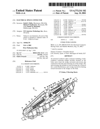
  • 5. U.S. Patent Aug.lO, 2004 Sheet 4 of s US 6,773,311 B2 1 12 FIG.5 22 98a 98b 98c FIG.6 102
  • 6. U.S. Patent Aug.lO, 2004 Sheet 5 of 5 US 6,773,311 B2 1 FIG.7 194 122 96 98a 98b 98c FIG.8
  • 7. US 6,773,311 B2 1 ELECTRICAL SPLICE CONNECTOR BACKGROUND OF THE INVENTION 2 pair of conductor contacting wedges into a wedge receiving area of a splice connector body, the wedges having projec- tions which are inserted into initial mounting portions of grooves in the body and subsequently moved into main 1. Field of the Invention The present invention relates to electrical splices and, more particularly, to an electrical splice connector and method of forming a splice of electrical conductors. 5 sections of the grooves; and connecting a clip to the splice connector body, the clip forming a direct barrier to move- ment of at least one of the wedges such that the projections are prevented from moving back into the initial mounting portions of the grooves and becoming inadvertently discon- 2. Brief Description of Prior Developments 10 nected from the splice connector body. Electrical splice connectors for connecting ends of elec- trical conductors to each other are well known in the art. U.S. Pat. No. 3,205,300 discloses one type of a splice which comprises pairs of wedge shaped gripping members. U.S. Pat. No. 6,193,565 discloses another type of splicing con- 15 nectar which comprises substantially open lateral sides. There is a desire to provide an improved electrical conductor splice connector which is easier to manufacture and assemble than conventional connectors, but also allows for open side loading of conductors into the connector. There is 20 also a desire to provide an anti-reversing movement function to movement of wedges in the connector. There is also a desire to provide the ability to overcome an anti-reversing movement function. There is also a desire to provide a splicing connector as a singular unit such that components of 25 the connector do not become inadvertently separated from each other before connection to the conductors. BRIEF DESCRIPTION OF THE DRAWINGS The foregoing aspects and other features of the present invention are explained in the following description, taken in connection with the accompanying drawings, wherein: FIG. 1 is a perspective view of an electrical conductor splice connector incorporating features of the present inven- tion; FIG. 2 is a partial top plan view of one end of the body of the connector shown in FIG. 1; FIG. 3 is a side elevational view of a first one of the conductor contacting wedges shown in FIG. 1; FIG. 4 is a side elevational view of a second one of the conductor contacting wedges shown in FIG. 1 intended to be used with the first conductor contacting wedge shown in FIG. 3; SUMMARY OF THE INVENTION In accordance with one aspect of the present invention, an electrical conductor splice connector is provided comprising a body; conductor contacting wedges movably mounted on the body; and at least one wedge movement anti-reverse clip connected to the body and contacting one of the wedges. FIG. 5 is a partial top plan view of the rear ends of a pair 30 of the conductor contacting wedges shown in FIG. 1; In accordance with another aspect of the present 35 invention, an electrical conductor splice connector is pro- vided comprising a body; and a pair of opposing conductor contacting wedges having bottom surfaces and outer lateral side surfaces slidably located on the body. A first one of the 40 wedges comprises a cantilevered bar at a top portion of the first wedge which slidably extends into a receiving area of a second one of the wedges to interlock forward and reward movement of the pair of wedges with each other. FIG. 6 is a perspective view of the anti-reverse clip shown in FIG. 1; FIG. 7 is a partial perspective view of an alternate embodiment of the connector shown in FIG. 1; and FIG. 8 is a perspective view of the anti-reverse clip shown in FIG. 7. DETAILED DESCRIPTION OF THE PREFERRED EMBODIMENT Referring to FIG. 1, there is shown a perspective view of an electrical conductor splice connector 10 incorporating features of the present invention. Although the present invention will be described with reference to the embodi- 45 ments shown in the drawings, it should be understood that the present invention can be embodied in many alternate forms of embodiments. In addition, any suitable size, shape or type of elements or materials could be used. In accordance with another aspect of the present invention, an electrical conductor splice connector is pro- vided comprising a body; and a pair of interlocked opposing conductor contacting wedges slidably located on the body. The body comprises wedge grooves. The wedges comprise protrusions slidably located in the wedge grooves. At least 50 one of the wedge grooves comprises a main section and an initial mounting portion located inwardly relative to the main section. During locating of the pair of wedges on the body the protrusion must be located in the initial mounting portion of the wedge groove before the protrusion can be 55 moved into the main section of the wedge groove. In accordance with one method of the present invention, a method of assembling an electrical conductor splice con- nector is provided comprising steps of inserting a wedge into a wedge receiving area of a splice connector body; and 60 connecting an anti-reversing clip to a top side of the splice connector body, the clip having an anti-reverse tab which projects inward into the wedge receiving area and into contact with the wedge. The connector 10 generally comprises a body 12, two pairs 14, 16 of conductor contacting wedges 18, 20, and two wedge movement anti-reverse clips 22. In alternate embodiments, the connector 10 could comprise additional or alternative components. The connector 10 is generally adapted to fixedly and electrically connect two conductors A, B to each other. In alternate embodiments, the connector 10 could be adapted to attach more than two conductors to each other. The body 12 generally comprises a one-piece frame member. However, in alternate embodiments, the body 12 could be comprised of more than one frame member. The body or frame 12 is preferably comprised of metal with a general C shaped cross section. The general C shape allows conductors A, B to be inserted into the connector 10 through the substantially open top side of the connector. However, in In accordance with another method of the present invention, a method of assembling an electrical conductor splice connector is provided comprising steps of inserting a 65 alternate embodiments, the frame member 12 could be comprised of any suitable type of material(s). In addition, the frame 12 could have any suitable type of shape. Refer-
  • 8. US 6,773,311 B2 3 ring also to FIG. 2, the frame member 12 comprises two opposite ends or sides 24a, 24b. In the embodiment shown ~he two opposite sides 24a, 24b are substantially mirro; Images of each other. However, in alternate embodiments, the two opposite sides could have different shapes. 5 Each side 24a, 24b comprises a bottom 26 and two lateral sides 28, 29 which forms a receiving area 34 for receiving one of the pairs of wedges 18, 20 and an end of one of the conductors A, B. The bottom 26 comprises a top side which includes two wedge grooves 36, 37. The wedge grooves 36, 10 37 each comprise a main section 38 and two initial mounting portions 40, 41. In the embodiment shown, the wedge grooves of the two sides 24a, 24b share the same rear of initial mounting portions 41. However, in alternate embodiments, they might not share the same rear initial 15 mounting portions 41. The two lateral sides 28, 29 have top sections with inwardly projecting ledges 42. This forms channels 44 for slidably receiving outward lateral sides of the wedges 18, 20 in the channels. The top sections of the frame 12 also comprises clip mounting posts 46. However, 20 in alternate embodiments, any suitable means for attaching the clips 22 to the frame 12 could be provided. Referring now also to FIGS. 3, 4 and 5, one of the pairs 14, 16 of the wedges 18, 20 will be described. In this embodiment, the pairs 14, 16 of wedges are identical to each 25 other; merely being orientated in reverse directions relative to each other. However, in alternate embodiments, the pairs of wedges could be different from each other. In another alternate embodiment, a set of wedges for each conductor A, B could comprise more than two wedges. In another alter- 30 nate embodiment, one or both sides 24a, 24b could comprise merely a single wedge rather than a pair of wedges. Each of the first wedges 18 generally comprise a bottom side 48, a top side 50, an inward facing side 52, and an outward facing side which is located in one of the channels 35 44. The bottom side 48 comprises two projections 54, 56. In alternate embodiments, the bottom side 48 could comprise more or less than two projections. The top side 50 generally comprises a projection 58 located at a rear end 60 of the wedge 18. The projection 58 forms a wedge retract/advance 40 tab. One function of the tab 58 is that it can be struck with a hammer allowing the installer to advance and retract the wedges 18, 20. The shape of the wedge retract/advance tab is conductive to striking with a hammer, yet streamlined enough so that when the connector is pulled through roller 45 blocks, the wedge retract/advance tabs do not get caught so as to restrict the polling or to cause the conductor to disengage from the wedges. The projection 58 forms a contact surface 64 at its front side. The projection 58 extends out of the receiving area 34 at the top of the frame 12. The 50 contact surface 64 is adapted to be a hit by a tool, such as a hammer, when attempting to remove the wedges from a gripping engagement with one of the conductors A, B. In an alternate embodiment, the projection 58 might not be pro- vided. A portion of the back surface of the tab 58 is straight 55 and perpendicular to the conductor gradations 98a-98c of the anti-reverse tab 22. This is another function of the tab 58 in that it provides a good indicator that the wedges are in the correct position for the type of conductor installed. The inward facing side 52 comprises a projection 62 60 located proximate the projection 58. In the embodiment shown, the projection 62 has a general cantilevered bar shape. However, in alternate embodiments, the projection 62 could have any suitable type of shape. The inward facing side 52 also comprises a separated section 66 forming a 65 gripping surface for gripping onto one of the conductors A, B. In alternate embodiments, any suitable type of gripping 4 surface on the inward facing side 52 could be provided. The gripping surface 66 has a general concave shape to form a conductor groove. The top side 50 also comprises serrations 68 (see FIG. 1) along a majority of its length. Each of the second wedges 20 generally comprises a bottom side 70, a top side 72, an inward facing side 74, and an outward facing side which is located in one of the channels 44. The bottom side 70 comprises two projections 76, 78. In alternate embodiments, the bottom side 70 could comprise more or less than two projections. The top side 72 generally comprises a projection 80 located proximate its rear end 82. The projection 80 comprises an aperture 84 therein. Referring also to FIG. 5, the aperture 84 is sized and shaped to be able to slidably receive the bar shaped projec- tion 62 of the opposite wedge 18 therein. The inward facing side 74 also comprises a serrated section 86 forming a gripping surface for gripping onto one of the conductors A, B. In alternate embodiments, any suitable type of gripping surface on the inward facing side 74 could be provided. The gripping surface 86 has a general concave shape to form a conductor groove. In the embodiment shown, in order to mount one of the pairs of wedges 18, 20 to the frame 12, the wedges 18, 20 are mounted to each other in relatively close proximity. The two gripping surfaces 66, 86 face each other. The bar shaped projection 62 extends into the aperture 84. The pair of wedges 18, 20 are then inserted into the receiving area 34. As the wedges 18, 20 are inserted, the front bottom side projections 54, 76 extend into the front initial mounting portions 40 of the grooves 36, 37. Likewise, the rear bottom side projections 56, 78 extend into the rear initial mounting portions 41 of the grooves 36, 37. The wedges 18, 20 are then moved outward relative to each other such that the bottom side projections 54, 56, 76, 78 extended into the main portions 38 of the grooves 36, 37. The wedges 18, 20 are then moved forward towards the outward ends of the grooves 36, 37. This causes a misalignment of the bottom side projections 54, 56, 76, 78 with the initial mounting portions 40, 41 of the grooves 36, 37. When the wedges 18, 20 are moved outward relative to each other, portions of their top sides 50, 72 are located under the inward projecting ledges 42. With the bottom side projections 54, 56, 76, 78 restrained in the main portions 38 of the grooves 36, 37, and portions of the wedges being constrained in the channels 44 by the inward projecting ledges 42, the wedges 18, 20 are constrained to a sliding movement along the paths of the grooves 36, 37. The grooves 36, 37 are angled relative to each other. As the wedges 18, 20 move towards the outer ends of the frame 12 the gripping surfaces 66, 86 moved towards each other. ~ the gripping surfaces 66, 86 move towards each other, the wedges 18, 20 are able to grasp onto one of the conductors A, B located between the two wedges. As noted above, the bar shaped projection 62 is located in the aperture 84. This provides an interlocking engagement between the two wedges 18, 20 of each pair of wedges. This interlocking engagement insurers that the two wedges 18, 20 will move outward and inward relative to the end of the frame 12 in substantial unison with each other. In alternate embodiments, an interlocking engagement between the pair of wedges might not be provided. Alternatively, any suitable type of interlocking engagement between the opposing pair of wedges could be provided. Regardless of the position of the opposing wedges, the bar projection 62 on the first wedge 18 can preferably always interface with the rectangular hole 84 on the second wedge
  • 9. US 6,773,311 B2 5 20. One purpose of the wedge interlock configuration is that it insures that the wedges always advance and retract at the same rate in relation to each other. The pressure from each of the wedge conductor grooves is always applied symmetri- cally onto the conductor when the wedges are advanced. 6 prise alternative or additional sections. The anti-reverse tab 102 and the serrations 68 on the wedge 18 form a wedge anti-reverse mechanism for the connector 10. These com- ponents work together to allow the wedges to advance in one 5 direction only; in an outward direction towards the ends of the connector frame 12. Another purpose of the interlock configuration is that it helps insertion of the conductor into the connector during installation. Typically, during installation, the end of the conductor is cut to remove any frayed strands. The end of the conductor usually acquires a slight curvature; usually 10 referred to as "bananaing". The curvature or "bananaing" makes it difficult for the conductor to be inserted into a straight channel, such as the channel along the two opposing wedge conductor groove surfaces 66, 86. The cantilevered bar projection 62 allows the curved end of the conductor to 15 be swept under the bar projections 62 such that the conduc- By design, when the conductor is inserted in between one set of wedges, the wedges are moved forward towards the nose or end of the connector. The wedges close applying pressure between the conductor grooves of the wedges and the conductor. As tension is applied axially on the conductor away from the connector, the wedges advance to increasing the pressure. As the wedges move forward the anti-reverse tab 102 of the clip 22 clicks along the successive serrations 68 on the wedge 18. The serrations 68 preferably have a saw tooth serrations design which allows the tab 102 to advance into the next serration, but does not allow the tab 102 to go tor portion under the bar projection is properly aligned in the wedge conductor grooves. With the end under the bar projection 62, the installer can then straighten the conductor back to the opposite direction. Thus, this prevents the wedge 18 from reversing and decreasing pressure on the conductor. by pushing it down into the channel between the wedge 20 conductor groove surfaces 66, 86 using the bar projection 62 The anti-reverse tab 102 extends in a general orthogonal direction relative to the removal tab 100. The removal tab 100 allows a tool such as a slotted screwdriver, to be inserted under the tab 100 for lifting the tab 100 upward. By lifting this removal tab 100 upward, the anti-reverse tab 102 disengages from the wedge serrations 68 on the wedge 18. as a fulcrum. As noted above, the connector 10 includes two wedge movement anti-reverse clips 22. In an alternate embodiment, more or less than two wedge movement anti-reverse clips could be provided. The two wedge movement anti-reverse clips are identical to each other. However, in alternate embodiments, the wedge movement anti-reverse clips could be different from each other. The anti-reverse clips 22 are each preferably comprised of a single stamped and formed sheet metal member. However, in alternate embodiments, the anti-reverse clips could be comprised of more than one member, and could be comprised of any suitable type of material(s) formed by any suitable type of manufacturing process. Referring also to FIG. 6, each of the connector anti- reverse clips 22 generally comprises a main section 90, a front section 92, and a rear section 94. The main section 90 generally comprises mounting holes 96 and markings 98a, 98b, 98c on a top side thereof. The clips 22 are located on the top side of the frame 12 with the mounting posts received in the mounting holes 96. The mounting posts 46 are then deformed to fixedly attach the clips 22 to the frame 12. In an alternate embodiment, any suitable means for mounting the clips 22 to the frame 12 could be provided. The clip 22 has the markings 98a-98c which are used as features to indicate the position of the wedges 18, 20 for proper conductor installation. The markings 98 are used as graduation markings corresponding to conductor sizes that the connector 10 is adapted to accommodate. In other words, the anti-reverse clip comprises desired wedge location indi- cia for multiple types of conductors, the indicia being located on a top side of the clip. During installation of the conductor, the wedges 18, 20 are advanced such that the conductor grooves on the wedges tighten around the con- ductor. When the wedges have been installed correctly on a particular conductor size, the back of the wedge 18 becomes aligned with the proper conductor graduation on the clip 22. This is a visual indicator to the installer that the connector 10 has been properly installed for a particular size conductor. In an alternate embodiment, the markings 98a-98c might not be provided, or the connector 10 could be provided with any suitable type of wedge positioning indicia or indicator. The front section 92 generally comprises a removal tab 100, an anti-reverse tab 102, and a notch 104 therebetween. In alternate embodiments, the front section 92 could com- 25 This allows the wedges 18, 20 to be retracted backward towards the center of the frame 12. This gives the installer the ability to make adjustments during installation. It also gives the ability to remove the connector once installed. As noted above, the clip 22 comprises a notch 104 located 30 between the two tabs 100, 102. By modifying the length of the notch 104, the spring stiffness of the anti-reverse tab 102 can be changed. The shorter the length of the notch 104, the stiffer the spring stiffness of the anti-reverse tab 102 will be. The longer the length of the notch 104, the less stiff the 35 spring stiffness of the into reverse tab 102 will be. Increasing the stiffness of the anti-reverse tab 102 decreases the ability of the wedges to slide freely in the frame 12. Decreasing the stiffness of the anti-reverse tab 102 increases the ability of the wedges to slide freely in the frame 12. During design of 40 the anti reverse clip 22, with adjustment, the desired "feel" of the sliding wedges can be achieved. In an alternate embodiment, the notch 104 might not be provided. The rear section 94 of the clip 22 comprises a wedge stop tab 106. The anti-reverse tab and the wedge stop tab extend 45 in a general same direction. The wedge stop tab 106 is provided to prevent the wedges from being retracted beyond a certain point on the frame 12. This can be an important feature to insure that the wedges 18, 20 remain in the frame 12 after assembly at the factory. During factory connector 50 assembly, the wedges 18, 20 are nested together and dropped into the frame 12. The wedges are then spread apart such that the outer lateral surfaces of the wedges are in contact with the outer walls of the frame 12. The wedges are then advanced forward on the wedge grooves of the frame 12 to 55 a point where the bottom side protrusions 54, 56, 76, 78 no longer have the ability to engage with the initial mounting portions 40, 41 of the slots 36, 37 and be removed from the frame 12. The anti-reverse clip 22 is then assembled onto the frame 12 and on top of the wedge 18. The wedge stop tab 60 106 abuts the rear side 60 of the wedge 18 and permanently prevents the wedge 18 from moving back to a position where the wedges can become disengaged from the frame 12 via the initial mounting portions 40, 41 of the slots 36, 37. The clip 22 is then fastened to the frame 12 thus preventing the 65 wedges 18, 20 from becoming detached from the frame 12. Referring now also to FIGS. 7 and 8, an alternate embodi- ment of the present invention will be described. In this
  • 10. US 6,773,311 B2 7 embodiment, the connector frame 12 and pairs of wedges 18,20 are the same as the embodiment shown in FIG. 1. The anti-reverse clip, however, is different. The clip 122 in this embodiment generally comprises a main section 190, a front section 192, and a rear section 194. The main section 190 is 5 the same as the main section 90 of the clip shown in FIG. 6. The main section 190 comprises mounting holes 96 and markings 98a-98c. The front section 192 is the same as the front section 92 of the clip shown in FIG. 6. The front section 192 comprises a removal tab 100, an anti-reverse tab 10 102, and a notch 104 therebetween. The rear section 194 is different than the rear section 94 8 9. An electrical conductor splice connector as in claim 1 wherein the anti-reverse clip comprises desired wedge loca- tion indicia for multiple types of conductors, the indicia being located on a top side of the clip. 10. An electrical conductor splice connector as in claim 1 wherein the clip comprises a sheet metal member. 11. An electrical conductor splice connector comprising: a body; conductor contacting wedges movably mounted on the body; and at least one wedge movement anti-reverse clip connected to the body and contacting one of the wedges wherein the anti-reverse clip comprises a portion with an anti- reverse tab which contacts one of the wedges, and a removal tab located proximate the anti-reverse tab, the removal tab being adapted to be moved away from the body to thereby move the anti-reverse tab. of the clip shown in FIG. 6. In this embodiment, the rear section 94 comprises a laterally inward projection 198. As shown in FIG. 7, the laterally inward projection 198 is 15 adapted to project behind the rear end 60 of the wedge 18. The projection 198, similar to the tab 106 shown in FIG. 6, limits rearward movement of the wedge 18 on the frame 12. However, the projection 98 can be formed merely by stamp- ing the sheet metal blank which forms the clip 122 and does not require a bending process as would be required with the clip 22 shown in FIG. 6. The design of the clip 122 in FIG. 12. An electrical conductor splice connector as in claim 11 wherein the anti-reverse clip comprises a notch located 20 between the anti-reverse tab and the removal tab. 8 also requires less material than the clip 22 shown in FIG. 6. This can reduce manufacturing costs. In alternate embodiments, any suitable type of anti-reverse clip could be 25 provided. It should be understood that the foregoing description is only illustrative of the invention. Various alternatives and modifications can be devised by those skilled in the art without departing from the invention. Accordingly, the 30 present invention is intended to embrace all such alternatives, modifications and variances which fall within the scope of the appended claims. What is claimed is: 1. An electrical conductor splice connector comprising: a body having a general C-shaped cross section; conductor contacting wedges movably mounted on the body; and 35 13. An electrical conductor splice connector as in claim 11 wherein the anti-reverse tab extends in a general orthogonal direction relative to the removal tab. 14. An electrical conductor splice connector comprising: a body; conductor contacting wedges movably mounted on the body; and at least one wedge movement anti-reverse clip connected to the body and contacting one of the wedges wherein the anti-reverse clip comprises an anti-reverse tab at a front end of the clip which engages serrations on one of the wedges and a wedge stop tab at a rear end of the clip. 15. An electrical conductor splice connector as in claim 14 wherein the anti-reverse tab and the wedge stop tab extend in a general same direction. 16. An electrical conductor splice connector as in claim 14 wherein the anti-reverse tab and the wedge stop tab extendat least one wedge movement anti-reverse clip connected to the body and contacting one of the wedges. 40 in general orthogonal directions. 2. An electrical conductor splice connector as in claim 1 wherein the anti-reverse clip is mounted to a top side of the body. 3. An electrical conductor splice connector as in claim 1 wherein the body comprises two wedge receiving areas, the 45 two wedge receiving areas comprising substantially open top sides. 4. An electrical conductor splice connector as in claim 1 wherein at least one of the wedges comprises serrations on a top side which are engaged by a portion of the anti-reverse 50 clip. 5. An electrical conductor splice connector as in claim 1 wherein the conductor contacting wedges comprise a pair of wedges which are connected to each other by a connection for forward and rearward movement on the body in unison 55 with each other. 17. An electrical conductor splice connector comprising: a body having a general C-shaped cross section; and a pair of opposing conductor contacting wedges having bottom surfaces and outer lateral side surfaces slidably located on the body, wherein a first one of the wedges comprises a cantilevered bar at a top portion of the first wedge which slidably extends into a receiving area of a second one of the wedges to interlock forward and reward movement of the pair of wedges with each other. 18. An electrical conductor splice connector as in claim 17 wherein the body comprises two wedge receiving areas having substantially open top sides. 19. An electrical conductor splice connector as in claim 17 wherein the body comprises wedge grooves and the wedges comprise protrusions slidable located in the wedge grooves, and wherein at least one of the wedge grooves comprises a main section and an initial mounting portion located inwardly relative to the main section, and wherein during 6. An electrical conductor splice connector as in claim 5 wherein a first one of the wedges comprises a bar slidably extending into a receiving area of a second one of the wedges. 7. An electrical conductor splice connector as in claim 6 wherein the bar is located proximate a top side of the first wedge and the receiving area is located proximate a top side of the second wedge. 60 locating of the pair of wedges on the body the protrusion must be located in the initial mounting portion of the wedge groove before the protrusion can be moved into the main section of the wedge grooves. 8. An electrical conductor splice connector as in claim 7 wherein the first wedge comprises an upwardly extending movement tab which extends out of the body. 20. An electrical conductor splice connector as in claim 17 65 further comprising at least one wedge movement anti- reverse clip connected to the body and contacting one of the wedges.
  • 11. US 6,773,311 B2 9 10 21. An electrical conductor splice connector as in claim 20 wherein the anti-reverse clip is mounted to a top side of the body. 22. An electrical conductor splice connector as in claim 21 wherein at least one of the wedges comprises serrations on a top side which are engaged by a portion of the anti-reverse clip. 29. An electrical conductor splice connector as in claim 28 wherein the member further comprises an anti-reverse tab for contacting serrations on a top side one of the wedges. 30. An electrical conductor splice connector as in claim 28 5 wherein the member comprises a sheet metal member. 23. An electrical conductor splice connector as in claim 20 wherein the clip comprises a sheet metal member. 24. An electrical conductor splice connector comprising: 10 a body; a pair of opposing conductor contacting wedges having bottom surfaces and outer lateral side surfaces slidably located on the body, wherein a first one of the wedges comprises a cantilevered bar at a top portion of the first 15 wedge which slidably extends into a receiving area of a second one of the wedges to interlock forward and rearward movement of the pair of wedges with each other; and at least one wedge movement anti-reverse clip mounted to a top side of the body and contacting one of the wedges, wherein the anti-reverse clip comprises a portion with 20 31. A method of assembling an electrical conductor splice connector comprising the steps of: inserting a wedge into a wedge receiving area of a splice connector body having a general C-shaped cross sec- tion; and connecting an anti-reversing clip to a top side of the splice connector body, the clip having a anti-reverse tab which projects inward into the wedge receiving area and into contact with the wedge. 32. A method as in claim 31 wherein the step of connect- ing the anti-reversing clip to the body comprises locating a wedge stop tab of the clip behind a rear end of the wedge to limit reward movement of the wedge on the body. 33. A method as in claim 31 wherein the step of inserting a wedge into the wedge receiving area comprises inserting the wedge with another wedge as a pair of wedges into the wedge receiving area, a portion of one of the wedgesan anti-reverse tab which contacts one of the wedges, and a removal tab located proximate the anti-reverse tab, the removal tab being adapted to be moved away from the body to thereby move the anti-reverse tab. 25 extending into a portion of another one of the wedges proximate a top sides of the wedges. 25. An electrical conductor splice connector as in claim 24 wherein the anti-reverse clip comprises a notch located between the anti-reverse tab and the removal tab. 26. An electrical conductor splice connector as in claim 25 wherein the anti-reverse clip further comprises a wedge stop tab at a rear end of the clip. 34. A method as in claim 33 wherein the wedge receiving area comprises a substantially open top side and the step of inserting a wedge into the wedge receiving area comprises 30 inserting the pair of wedges through the substantially open top side. 35. A method as in claim 31 wherein the clip comprises a sheet metal member. 27. An electrical conductor splice connector comprising; a body having a general C-shaped cross section; and 36. A method of assembling an electrical conductor splice 3s connector comprising steps of: a pair of interlocked opposing conductor contacting wedges slidably located on the body, wherein the body comprises wedge grooves, wherein the wedges comprise protrusions slidably located in the wedge grooves, wherein at least one of the wedge 40 grooves comprises a main section and an initial mount- ing portion located inwardly relative to the main section, and wherein during locating of the pair of wedges on the body the protrusion must be located in the initial mounting portion of the wedge groove before 45 the protrusion can be moved into the main section of the wedge groove. 28. An electrical conductor splice connector as in claim 27 further comprising a member attached to a top side of the body, the member comprising a stop tab for limiting reward so movement of the wedges on the body. inserting a pair of conductor contacting wedges into a wedge receiving area of a splice connector body having a general C-shaped cross section, the wedges having projections which are inserted into initial mounting portions of grooves in the body and subsequently moved into main sections of the grooves; and connecting a clip to the splice connector body, the clip forming a direct barrier to movement of at least one of the wedges such that the projections are prevented from moving back info the initial mounting portions of the grooves and becoming inadvertently disconnected from the splice connector body. 37. A method as in claim 36 wherein the clip comprises a sheet metal member. * * * * *
  • 12. UNITED STATES PATENT AND TRADEMARK OFFICE CERTIFICATE OF CORRECTION PATENT NO. : 6,773,311 B2 DATED : August 10, 2004 INVENTOR(S) : Mello et al. Page 1 of 3 It is certified that error appears in the above-identified patent and that said Letters Patent is hereby corrected as shown below: Column 7, Line 34, claim 1, should read: 1. An electrical conductor splice connector comprising: a body having a general C-shaped cross section; conductor contacting wedges movably mounted on the body; and at least one wedge movement anti-reverse clip connected to the body and contacting one of the wedges wherein the anti-reverse clip comprises a portion with an anti-reverse tab and a removal tab located proximate the anti- reverse tab. Column 8, Line 41, claim 17, should read: 17. An electrical conductor splice connector comprising: a body having a general C-shaped cross section; a pair of opposing conductor contacting wedges having bottom surfaces and outer lateral side surfaces slidably located on the body, wherein a first one of the wedges comprises a cantilevered bar at a top portion of the first wedge which slidably extends into a receiving area of a second one of the wedges to interlock forward and reward movement of the pair of wedges with each other; and at least one wedge movement anti-reverse clip mounted to a top side of the body and contacting one of the wedges, wherein the anti-reverse clip comprises a portion with an anti-reverse tab which contacts one of the wedges, and a removal tab located proximate the anti-reverse tab.
  • 13. UNITED STATES PATENT AND TRADEMARK OFFICE CERTIFICATE OF CORRECTION PATENT NO. : 6,773,311 B2 DATED : August 10, 2004 INVENTOR(S) : Mello et al. Page 2 of 3 It is certified that error appears in the above-identified patent and that said Letters Patent is hereby corrected as shown below: Column 9, Line 34, claim 27, should read: 27. An electrical conductor splice connector comprising: a body having a general C-shaped cross section; a pair of interlocked opposing conductor contacting wedges slidably located on the body, wherein the body comprises wedge grooves, wherein the wedges comprise protrusions slidably located in the wedge grooves, wherein at least one of the wedge grooves comprises a main section and an initial mounting portion located inwardly relative to the main section, and wherein during locating of the pair of wedges on the body the protrusion must be located in the initial mounting portion of the wedge groove before the protrusion can be moved into the main section of the wedge groove; wherein the connector further comprises an anti-reverse clip member attached to a top side of the body, the member comprising an anti-reverse tab for contacting serrations on a top side of one of the wedges and a removal tab located proximate the anti-reverse tab. Column 10, Line 6, claim 31, should read: 31. A method of assembling an electrical conductor splice connector comprising the ·steps of: inserting a wedge into a wedge receiving area of a splice connector body having a general C-shaped cross section; and connecting an anti-reversing clip to a top side of the splice connector body, the clip having a anti-reverse tab which projects inward into the wedge receiving area and into contact with the wedge and a removal tab located proximate the anti· reverse tab.
  • 14. UNITED STATES PATENT AND TRADEMARK OFFICE CERTIFICATE OF CORRECTION PATENT NO. : 6,773,311 B2 Page 3 of 3 DATED : August 10, 2004 INVENTOR(S) : Mello et al. It is certified that error appears in the above-identified patent and that said Letters Patent is hereby corrected as shown below: Column 10 (cont'd), Line 34, claim 36, should read: 36. A method of assembling an electrical conductor splice connector comprising steps of: inserting a pair of conductor contacting wedges into a wedge receiving area of a splice connector body having a general C-shaped cross section, the wedges having projections which are inserted into initial mounting portions of grooves in the body and subsequently moved into main sections of the grooves; and connecting a clip to the splice connector body, the clip forming a direct barrier to movement of at least one of the wedges such that the projections are prevented from moving back into the initial mounting portions of the grooves and becoming inadvertently disconnected from the splice connector body, wherein the clip comprises a portion with an anti-reverse tab which contacts one of the wedges, and a removal tab located proximate the anti-reverse tab. Claims 20, 21 and 29, should be cancelled. Signed and Sealed this Seventh Day of December, 2004 JONW.DUDAS Director ofthe United States Patent and Trademark Office