SlideShare a Scribd company logo
1 of 10
Download to read offline
USOO65440O2B1
(12) United States Patent (10) Patent No.: US 6,544,002 B1
Evans et al. (45) Date of Patent: Apr. 8, 2003
(54) METHOD OF CHEMICAL PRETREATMENT 5,755,558 A * 5/1998 Reinfelder et al. ......... 416/230
OF A LIGHTWEIGHT JET ENGINE FAN 5.830,548 A 11/1998 Andersen et al. .......... 428/36.4
BLADE 5,863,329 A 1/1999 Yamanouchi ............... 118/100
6,033,186 A * 3/2000 Schilling et al. ............ 416/233
(75) Inventors: Charles Richard Evans, Cincinnati, 6,099.257 A * 8/2000 Schilling .................... 416/229
OH (US); Kathryn Ann Evans, 6,287,080 B1 * 9/2001 Evans et al. ............ 416/229 A
Cincinnati, OH (US); Wendy 6,376,008 B1 * 4/2002 Steiner et al. ................ 427/96
Wen-Ling Lin, Niskayuna, NY (US); 6,454,536 B1 * 9/2002 Evans et al. ............ 416/229 A
Mark Alan Rosenzweig, Hamilton, OH
(US); Jeffrey Lynn Schworm, * cited by examiner
Delanson, NY (US)
(73) Assignee: General Electric Company, Primary Examiner Edward K. Look
Schenectady, NY (US) ASSistant Examiner J. M. McAleenan
(74) Attorney, Agent, or Firm Jonathan P. Miller; Carmen(*) Notice: Subject to any disclaimer, the term ofthis
patent is extended or adjusted under 35 Santa Maria; McNees Wallace & Nurick LLC
U.S.C. 154(b) by 0 days. (57) ABSTRACT
(21) Appl. No.: 10/039,394 Agrit blasting and alkaline etch Surface pretreatment that is
(22) Filed: Nov. 7, 2001 applied to a metallic airfoil. The metallic airfoil includes
7 pockets or cavities that have been fabricated into the airfoil
(51) Int. Cl.' .................................................. F01D 5/28 to reduce the weight ofthe airfoil.The pretreatmentincludes
(52) U.S. Cl. ................... 416/224; 416/233; 416/229 A; grit blasting the Surface of the pockets or cavities, followed
416/241 A; 428/613; 428/469; 5.s by Washing the airfoil and treating the airfoil in an alkaline
/889. etch bath. After any remaining Solution from the bath is
(58) Field of Search ................................. 416/224, 233, neutralized and within twenty-four hours of the end of the
pretreatment, primer is applied to the Surface of the pockets
or cavities. After the primer is applied to the Surface of the
pockets, a lightweight resin is injected into the pockets and
(56) References Cited bonds to the primer forming a mechanical bond with good
fracture toughness at elevated temperatures.
416/241A, 229 A, 243, DIG. 2, DIG. 5;
29/889.2; 427/377, 532,585; 428/613,
256, 469, 408
U.S. PATENT DOCUMENTS
5,192.586 A * 3/1993 Mertinooke et al. ........ 427/210 19 Claims, 2 Drawing Sheets
US 6,544,002 B1U.S. Patent
US 6,544,002 B1
1
METHOD OF CHEMICAL PRETREATMENT
OF A LIGHTWEIGHTJET ENGINE FAN
BLADE
FIELD OF THE INVENTION
The present invention relates generally to a gas turbine
blade component comprised of two or more components
made from different materials, and more particularly to a
proceSS used in the construction of a lightweight jet engine
fan blade.
BACKGROUND OF THE INVENTION
Gas turbine blades include, but are not limited to, gas
turbine power generation equipment and gas turbine aircraft
engines. A gas turbine includes a core engine having a
compressor to compress the air flow entering the core
engine, a combustor in which a mixture of fuel and the
compressed air is burned to generate a propulsive gas flow,
and a turbine which is rotatedby the propulsive gas flow and
which is connected by a larger diameter shaft to drive the
compressor. A typical front fan gas turbine aircraft engine
includes a high pressure turbine and a low pressure turbine,
located aft of the high pressure turbine, which is connected
by a Smaller diameter coaxial shaft to drive a front fan,
located fore ofthe compressor. The compressor may option
ally include a low pressure compressor and a high pressure
compressor, both located aft of the fan. The low pressure
compressor is Sometimes called a booster compressor or
Simply a booster.
The fan, the compressor blades and turbine blades have
airfoils each include a airfoil portion attached to a Shank
portion and are attached to a rotating disc. Stator Vanes are
Stationary airfoils which are attached to a non-rotatingStator
casing or engine frame. Stator Vanes direct the flow of air
from the rotating blades. Typically, there are alternating
circumferential rows of rotor blades extending outwardly
from the discS and Stator Vanesextending inwardly from the
casings. When present, a first and/or last row ofStator Vanes
(also called inlet and outlet guide vanes) may have their
radially-inward ends also attached to a non-rotating gas
turbine Stator casing.
Conventional airfoil designs used in the compressor Sec
tion at the engine typically have airfoil portions that are
made entirely of metal, Such as titanium or titanium alloys,
or are made entirely of composite. A“composite' is defined
to be a material having any (metal or non-metal) fiber
filament embedded in any (metal or non-metal) matrix, but
the term “composite' does not include a metal fiber embed
ded in a metal matrix.The term “metal' includes alloyssuch
as titanium alloy Ti 6-4. An example of a composite is a
material having graphite filaments embedded in an epoxy
CS.
Fan blades are large and are fore ofthe compressor, while
compressor blades in the front of the engine are large and
become progressively Smaller as the combustor portion of
the engine is approached. Conversely, turbine blades are
Small and become progressively larger with departure from
the combustor portion of the engine. Fan blades are usually
the largest blades in the engine.
The all-metal blades, including costly wide-chord hollow
blades used as fan blades, are heavier in weight which
results in lower fuel performance and require Sturdier blade
attachments, while the lighter all-composite blades are more
Susceptible to damage from ingestion events also known as
foreign object damage (“F.O.D."). Known to the art are
15
25
35
40
45
50
55
60
65
2
hybrid blades including a composite blade having an airfoil
shape which is coveredby a Surface cladding (with only the
blade tip and the leading and trailing edge portions of the
Surface claddingcomprising a metal) forerosion and F.O.D.
The fan blades typically are the largest (and therefore the
heaviest)bladesin agasturbine aircraftengine, andthe front
fan blades are usually the first to undergo F.O.D.
Various designs are under construction for gas turbine
blades having reduced weight for use as gas turbine fan
blades that are comprised of a combination of monolithic
metal and non-metal materials and have the capability to
resist F.O.D. Some of these designs include lightweight
inserts molded into cavities of metal blades. The cavities are
regions of the blade that have had metal removed to lighten
the blade and the monolithic lightweight inserts are added to
restore an aerodynamic shape to the blade that was altered
by the inclusion ofthe cavity in the blade design. While both
the lightweight inserts and the metallic portion of the blade
are relatively monolithic materials having excellent
Strengths, the interface between the lightweight inserts and
the metallic portion of the blade is the weak link wherin
debonding and failure is most likely to occur. Typically,
failures occur due to debondingbetween a primer applied to
the metallic blade and the blade itself.
What is needed are improvements in the adhesion
between the lightweight inserts molded into blade pockets
and the metallic material of the blades at this interface.
Pretreatment processes of lightweightjet aircraft fan blades
that promote adhesion between the metal portion of the
blade and lightweight inserts can provide Such improve
mentS.
SUMMARY OF THE INVENTION
The present invention is directed to improvements in the
treatment of an aircraft engine fan blade comprised of
lightweight inserts positioned in metal pockets. The fan
blade is manufactured to have reduced weight by removing
metal at preselected locations. These preselected locations
take the form of pockets. The locations of the pockets are
preSelected So as not to adversely affect the Structural
integrity of the blade. The aerodynamic flow of air over the
blade is restored by filling in the pockets with the light
weight inserts.
The bonding between the blade and the inserts is
improved by a treatment method. First, the blade is pre
treated by grit blasting, using a preselected grit to achieve a
preSelected Surface finish, cleaning the Surface, followed by
a uniform etch in etchant followed by cleaning, prior to
application of a primer. The etchant may be an alkaline
Solution, an acid Solution, or a sequence that includes both
alkaline and acid Solutions, provided that cleaning and
neutralization occurs between Successive treatments in Solu
tions.The lightweightinsert material isapplied to the pocket
after the pocket is coated with a primer.
The advantage ofthe present invention isthat the problem
of poor bonding between the primer coating on the Surface
ofthe blade pockets and the metalthatcomprisesthe Surface
of the blade pockets is substantially reduced. This results in
longerlife ofthe fanblade andsmooth airflow overthe blade
without out ofbalance conditions that can arise with loSS of
inserts. The present invention is a Surface pretreatment prior
to applying primer to the Surface of the blade pockets. The
increase in the bond Strength between the primer and the
Surface ofthe blade pockets createsbetter adhesion between
the primer and the metal Surface of the blade, aid prevents
delamination or loss of the inserts from the pockets.
US 6,544,002 B1
3
Other features and advantages of the present invention
will be apparent from the following more detailed descrip
tion of the preferred embodiment, taken in conjunction with
the accompanying drawings which illustrate, by way of
example, the principles of the invention.
BRIEF DESCRIPTION OF THE DRAWINGS
FIG. 1 is a perspective of an aircraft engine fan blade,
showing pockets formed therein;
FIG. 2 is a graph of the performance ofseveral different
titanium Surface preparationsasa function offracture tough
ness at 310 F.
DETAILED DESCRIPTION OF THE
INVENTION
This invention is directed toward the chemical treatment
of a metallic fan blade, Such as used in jet engines, that has
been machined to produce a preselected number of pockets
in preselected locations on the blade. One such fan blade 10
is depicted in FIG. 1, showing pockets 12 formed in the
airfoil surface 14. The purpose ofthis chemical treatment is
to attain improved bond strength between the metallic blade
pockets and the primer coat which is applied to the Surface
of the blade pockets, and to attain greater bond Strength
between a polymeric resin that comprises the lightweight
inserts and the primer coat. The fan blade also has a dovetail
portion 16, which does not undergo chemical treatment.
Fan blades used in jet engines consist of a blade portion
and a dovetail portion which attaches a blade to the fan disc.
The dovetail portion of the part requires no chemical
treatment, and this invention is directed to the airfoil portion
of the blade.
The airfoil portion of the blade should first be inspected
to ensure that there are no nicks, dings, bent or deformed
material, and that there is no unusual discoloration. Pockets
are machined or cast into the Surface of the blade. The
as-manufactured Surface finish on the pockets of the airfoil
portion ofthe blade is notcriticalto the process ofproducing
an optimized Surface for bonding an insert within a pocket.
The airfoil portion of the blade optionally may be cleaned
prior to thisprocess to remove any foreign material from the
surface. Afixture on which the dovetail portion of the blade
is to be hung for Subsequent processing in accordance with
this invention should be inspected to ensure that the blade is
held rigidly without movement thatcan damage the edges of
the airfoil portion of the blade.
This process makes use ofdeionized water in a number of
the proceSS Steps. The deionized water used in this proceSS
should have a pH in the range of about 6.5 to about 7.5 and
have a resistivity of at least about 50,000 ohms/cm in order
to minimize Smut formation on the blade. Smut formation is
detrimental to bonding and should be eliminated or reduced
to the maximum extent possible.
The first Step in the process of the present invention is to
grit blast at leastthe surface ofthe airfoilportion ofthe blade
that includes the pockets with a preselected grit type at a
preSelected pressure for a preselected period of time. The
purpose of the grit blasting is to obtain a Substantially even
surface finish to increase the ability of the primer to bond to
the metallic Surface of the pockets. In a preferred
embodiment, the Surface ofthe blade pockets are gritblasted
usingAl-O, the size of the grit being in the range of about
120grit to about 180grit, at a pressure in the range of about
40 to about 60 psi. Oxides of other materials such as
refractory metal oxides, for example ZrO or SiO may be
5
15
25
35
40
45
50
55
60
65
4
substituted for alumnia. The dovetail portion of the part
typically is masked So that it is unaffected by grit blasting.
After the grit blasting is complete, the Surface of the
airfoil portion of the blade that was grit blasted is rinsed. In
one embodiment, the airfoil portion of the blade is rinsed
with deionized water for a preselected period of time to
remove any loose particles from the Surface of the blade. In
a preferred embodiment, the airfoil portion of the blade is
Sprayed with deionized water for at least about three min
utes. In an alternate embodiment, the blade is rinsed with a
Solvent which is miscible with water, and which has a
volatility sufficient to accelerate the removal of liquid from
the surface of the blade without leaving a stain. Desirably,
the Solvent also can remove any grease and other contami
nants from the Surface ofthe blade. The solvent used to rinse
the airfoil portion of the blade is preferably an alcohol
Selected from the group consisting of ethanol, propanol,
methanol or isopropyl alcohol. Isopropyl alcohol is the
preferred alcohol used to rinse the part. Once the part has
been rinsed with the solvent, it may be wiped with a
Solvent-Saturated cloth and dried with a lint-free cloth.
Drying is accomplished to prevent the formation of water
Stains. These water Stains have been found to detrimentally
affect bonding of the insert within a pocket.
The airfoil portion of the blade is then immersed in an
alkaline etch bath in order to complete the creation of a
proper Surface finish for the application of a primer coat. If
deionized water was used to rinse the airfoil portion of the
blade, the airfoil portion of the blade must be immersed in
an alkaline etch bath before the water dries on the Surface of
the blade to prevent formation of water stains. The water
Stains detrimentally affect the adhesion of Subsequently
applied primer.The dovetail portion ofthe blade typically is
not immersed in the alkaline etchbath.As a practical matter,
the tank that contains the alkaline etch bath should be made
of a material or materials which are non-reactive with the
alkaline bath in order to prevent the dissolution of any
portion of the tank into the solution of the bath. The
preferred alkaline component of the bath is TURCO 5578, a
proprietary alkaline Solute which is currently manufactured
by Elf Atochem. TURCO 5578 is comprised primarily of
NaOH and traces of petroleum distillates. The preferred
composition of the alkaline etch bath is deionized water
combined with a Sufficient amount of TURCO 5578 in
Solution to ensure that the concentration ofthe TURCO 5578
is about 360 to about 480 grams of TURCO 5578 per liter
of deionized water. Additionally, a preselected amount of
ferric Sulfate is added to the TURCO 5578 Solution to ensure
a concentration ofiron ofabout 0.05 to about 0.15 gramsper
liter of deionized water. The addition of ferric Sulfate to the
alkaline etch bath maintains an iron concentration in the bath
so that the etch rate is not greatly affected by the build up of
dissolved Timetal in the bath solution. The temperature of
the bath shouldbe in the range ofabout 180° F to about 185
F. to minimize Smut formation and provide a relatively even
etch. The airfoil portion of the blade should remain in the
bath for a preselected period of time Sufficient to provide a
uniform surface finish. Preferably, the airfoil portion of the
blade should remain in the bath for a time of about 15 to
about 17 minutes. Continuous agitation of the alkaline etch
bath is preferable in order to further reduce Smut formation
on the airfoil portion of the blade. The etch rate of the
titanium or titanium alloy should preferably be about 0.3
mils to about 0.7 mils per hour. The concentration of
titanium in the alkaline etch bath should preferably not
exceed 120 parts per million during the etching process to
maintain the proper etch rate.
US 6,544,002 B1
S
As the airfoil portion of the blade is removed from the
alkaline bath, the airfoil portion of the blade is continuously
rinsed with deionized water for a preselected period of time
in order to prevent any solute from the alkaline bath from
drying on the part and leaving a Stain on the part. The rinse
Step preferably has a duration of at least three minutes in
order to wash most of the alkaline solution from the airfoil
portion ofthe blade. During the rinsingprocedure, the airfoil
portion of the blade optionally may be brushed to remove
any Smut that may be formed. In a preferred embodiment,
the brush used should be a soft brush made of a synthetic
material, Such as a nylon brush, to avoid removing addi
tional metal from the surface of the airfoil portion of the
blade. The airfoil portion of the blade remains wet while it
is being brushed in order to prevent the airfoil portion ofthe
blade from drying with resultant formation of water stains
on the Surface which adversely affect adhesion of primer.
Once the Smut has been removed from the Surface of the
airfoil portion ofthe blade, the airfoil portion of the blade is
placed into an immersion bath of deionized water at a
preSelected temperature, for a preselected period of time in
order to neutralize any remaining alkaline Solution. The tank
that contains the deionized water bath is comprised of a
material or materials that are non-reactive with the deionized
waterbath in order to prevent the dissolution ofany portion
of the tank into the water bath. The deionized water bath is
maintained at the preselected temperature during the entire
time that the airfoil portion ofthe blade is in the bath. Once
the airfoil portion of the blade is placed into the immersion
bath, the bath is agitated for a preselected period of time to
minimize Smut formation on the airfoil portion of the blade.
In a preferred embodiment, the temperature of the immer
sion bath should remain in the range of about 165 F. to
about 185 F. Ifthe temperature ofthe water is much higher
than about 185 F., then water flashes upon removal of the
blade and stains form. If the temperature is lower that about
165 F., then Smut formation on the blade is promoted,
which is still hot from the alkaline treatment. The airfoil
portion of the blade should remain in the bath for a period
oftime not to exceed three minutes to prevent the formation
of Smut on the airfoil portion of the blade.
As the airfoil portion of the blade is being removed from
the deionized water bath, it is continuously sprayed with
deionized water at a preselected temperature in order to
prevent any water Stains from forming on the hot airfoil
portion of the blade. The deionized water used in the spray
is preferably at room temperature in order to prevent the
deionized water from rapidly drying on the Surface of the
airfoil portion of the blade and leaving water marks. The
airfoil portion of the blade should be sprayed for at least
three minutes. After the airfoil portion of the blade is
removed from the deionized water bath, it may be brushed
to remove any Smut which formed on the airfoil portion of
the blade during the deionized water bath. In a preferred
embodiment, the brush is a Soft, Synthetic preferably nylon
brush in order to avoid Scraping any metal offofthe Surface
of the blade.
Once the part has been brushed, it is placed into a Spray
rinse comprised of deionized water within a preselected
temperature range, for a preselected period of time in order
to remove any alkaline Solution remaining on the blade. In
a preferred embodiment, the temperature of the Spray rinse
is maintained at room temperature for the duration of the
Spray Step in order to prevent the deionized water from
drying on the Surface of the blade and leaving water Stains.
AS the part is being removed from the deionized water
Spray, and before any portion of the part is allowed to dry,
15
25
35
40
45
50
55
60
65
6
the part is visually inspected to determine if it there are any
waterbreakson the Surface oftheblade pockets. Ifany water
break is evident, indicative ofa Stain or an impurity, the part
must be reprocessed, beginning with immersion in the
alkaline bath. If the part requires reprocessing, it should be
placed into the alkaline bath before any of the water on the
Surface of the blade dries in order to prevent water Stains
from forming on the surface of the blade.
After the part has been inspected Successfully for any
water breaks, and found to be free of water breaks, the part
is immersed in an acid bath comprising deionized water and
a preselected concentration of nitric acid for a preselected
period of time. The purpose of the bath is neutralize any
remaining alkaline etch Solution remaining on the Surface of
the blade. Upon immersion of the blade into this bath, the
bath is agitated for a preselected period of time. The acid
bath shouldpreferably include asolution about 1 to about 15
percent nitric acid by mass in deionized water in order to
neutralize any remaining alkaline Solution on the blade. In a
preferred embodiment, the acid Solution is about ten percent
nitric acid. The temperature of the acid bath is preferably in
the range ofabout 65 F. to 85 F. and the blade is immersed
in the acid bath for a time of about one to about two minutes
in order to minimize the formation of Smut on the blade.
While the airfoil portion of the blade is being removed
from the acidbath, it iscontinuously sprayed with deionized
water at a preselected temperature in order to prevent the
acid Solution from drying on the blade and leaving any
marks on the blade. The blade is rinsed for at least three
minutes in order to remove any acid Solution remaining on
the surface of the blade. While the blade is being rinsed, it
preferably is brushed to remove any Smut which formed
during the acid bath. In a preferred embodiment, the blade
is brushed with a wet nylon brush in order to prevent any
metal from being removed from the blade. In a preferred
embodiment, the temperature of the Spray rinse is main
tained at room temperature for the duration ofthe Spray Step
in order to minimize evaporation of the water which would
leave water stains on the airfoil portion of the blade.
As the airfoil portion of the blade is removed from the
deionized water Spray rinse, the blade is inspected for any
water break. If the blade shows any water break, it must be
processed again beginningwith the alkaline bath. The airfoil
portion of the blade must be placed in the alkaline etch bath
before any portion of the airfoil portion of the blade is
allowed to dry in order to prevent the any water Stains from
forming on the Surface of the airfoil portion blade.
After the part hasbeen checked for water break and if no
water break is found, the part may be rinsed with a Solvent
which is miscible with water,which will not cause a stain on
the Surface of the blade, and which will remove any grease
and other contaminants from the Surface of the blade. The
Solvent used to rinse the blade is preferably an alcohol, as
previously set forth. Once the part has been rinsed with the
Solvent, it may be wiped with a Solvent Saturated cloth and
dried with a lint-free cloth.
The blade is then dried using forced air in a fresh air
circulating oven at a preselected temperature for preselected
period of time. The airfoil portion of the blade preferably is
dried for a period oftime between about 10 minutes to about
60minutesat a temperature between about 130 F. and about
300 F. and preferably between about 30 minutes and about
60minutesat a temperature between about 135 F. and about
180° F. or alternatively for a period of time between about
10 minutes and about 30 minutes at a temperature between
about 250 F. and about 300° F in order to thoroughly dry
the blade. The blade then is dried with a lint-free cloth.
US 6,544,002 B1
7
Within twenty four hours ofthe drying step, the surface of
the blade pockets are coated with a Standard non-chromated
Spray primer to achieve a preselected cured primer thick
neSS. If a chromated primer is used, a weaker bond will be
formed between the surface of the blade and the primer and
a weaker bond will be formed between the polymer resin
used for the insert and the primer. The preferred polymer
currently is polyurethane resin, although other resins dis
playing Similar properties may be Substituted. If more than
twenty four hours passes between the drying Step arid the
application of the primer, a relatively large amount of
titanium oxide, caused by reaction of air with the Surface of
the titanium alloy blade will form on the surface ofthe blade
which will ultimately weaken the bond between the metal
Surface of the pockets and the lightweight inserts. The
amountofprimercoatthickneSS applied to the blade pockets
preferably is sufficient to obtain a cured thickness between
about 0.00002 and about 0.00020 inches. In a preferred
embodiment, the primer is TYPLY BNF), a proprietary
non-chromated primer available from Lord Corporation of
Erie, Pa. Once the primer has been applied to the blade
pockets, the primer is cured in two stages at pre-Selected
temperatures and for pre-Selected periods of time. The
primer preferably is cured for a minimum of 30 minutes at
a temperature range ofabout 65 F. to about 85 F. and then
immediately followed by curing in the range of about 60
minutes to about 90 minutes at a temperature in the range of
about 250 F. to about 300° F. The resin is applied as set
forth in U.S. patent application Ser. No. 09/044,255 incor
porated herein by reference.
The blade pockets that are prepared using the methods
and procedures of the present invention display improved
fracture toughness at 310 F. when compared to blades
having pockets prepared using various other methods. The
fracture toughness performance of finished blades having
pockets prepared by Several techniques and then having the
pockets filled with the same polyurethane resin as well asby
the methods Set out by the current invention preparation
techniques prior to applying a primer are Set forth in FIG. 2,
all ofwhich were tested at about 310 F. Each method refers
to the method preparation techniques prior to applying a
primer. AS can be seen, the mode 1 fracture toughness of
blade pockets prepared in accordance with the present
invention displays a significant improvement over the base
line method of grit blasting using 36 grit at 80 psi.
FIG. 2. is a graph that illustrates the improvement that the
present invention provides over other possible fan blade
treatments. Five data points were gathered for each type of
treatment. The lines running vertically illustrate the maxi
mum and the minimum Mode 1 fracture toughness at 310
F. The shaded rectangles represent 75% of the data points
gathered for each type of treatment. The horizontal line
within the shaded rectangle represents the mean value of the
data points. The black dot within the Shaded rectangle
represents the median value of the data points.
As shown in FIG. 2, looking to the mean of the data
points,peening with an intensity of 6-10 N on the Almen N
Scale and 120 grit at 50 psi produced a fracture toughneSS
equivalent to the toughness of the baseline method, while
peening with less intensity, 6-10 A on the Almen A Scale
produced an inferior fracture toughness. Without any pre
treatment of the pockets, a fracture toughneSS was obtained
intermediate between the two methods employing peening.
However, the present invention yielded fracture toughneSS
improvements over the baseline method of between about
70% to about 200%.
While the invention has been described with reference to
a preferred embodiment, it will be understood by those
15
25
35
40
45
50
55
60
65
8
skilled in the art that various changes may be made and
equivalents may be substituted for elements thereof without
departing from the Scope ofthe invention. In addition, many
modifications may be made to adapt a particular situation or
material to the teachings of the invention without departing
from the essential Scope thereof. Therefore, it is intended
that the invention not be limited to the particular embodi
ment disclosed as the best mode contemplated for carrying
out this invention, but that the invention will include all
embodiments falling within the Scope of the appended
claims.
What is claimed is:
1. A method of producing an aircraft engine blade, com
prising an airfoil portion and a dovetail portion, and having
atleast one pocketin the airfoilportion,comprisingthe Steps
of:
providing an aircraft engine fan blade having at least one
pocket in the airfoil portion;
grit blasting a Surface ofthe airfoil portion having at least
one blade pocket with a preselected type of grit, at a
preSelected Size and at a preselected pressure to effect
a uniform Surface finish;
Washing the Surface with a Solvent that is miscible in
water and has a volatility Sufficient to accelerate the
removal of liquid from the Surface without leaving a
Stain;
drying the Surface by removing the Solvent;
immersing the airfoil portion of the blade in an alkaline
etch bath while agitating the etch bath to further effect
a uniform Surface finish;
removing the airfoil portion of the blade from the bath
without allowing the airfoil portion of the blade to dry;
neutralizing the alkaline Solution on the Surface of the
airfoil portion of the blade;
Washing the Surface with a Solvent;
drying the Surface wherein the Solvent is removed from
the surface of the airfoil portion of the blade without
forming Stains,
applying a primer to the at least one pocket of the airfoil
portion of the blade;
curing the primer;
injecting a polymeric resin into the at least one pocket;
and
curing the resin.
2. The method of claim 1, wherein the alkaline etch bath
further comprises a preselected concentration of NaOH and
a predetermined iron concentration.
3. The method of claim 2, wherein the concentration of
NaOH is about 360 grams to about 480 grams per liter of
deionized water and the concentration of iron is about 0.05
to about 0.15 grams per liter of deionized water.
4. The method of claim 3, wherein the NaOH solution is
TURCO 5578 in deionized water.
5. The method ofclaim 1, wherein the step ofneutralizing
further comprises the Step of
immersing the airfoil portion of the blade in a deionized
water bath at a preselected temperature for a prese
lected period of time.
6. The method ofclaim 1, wherein the step ofneutralizing
further comprises the Step of
immersing the airfoil portion of the blade in an acid
Solution, having a predetermined concentration, at a
preSelected temperature for a preselected period of
time.
US 6,544,002 B1
9
7. The method as in claim 6, wherein the step of neutral
izing further comprises the Step of:
immersing the airfoil portion of the blade in a deionized
water bath at a preselected temperature for a prese
lected period of time after immersion in the acid
Solution.
8. The method ofclaim 1, wherein the step ofneutralizing
further comprises the Steps of
immersing the airfoil portion of the blade in a deionized
water bath at a preselected temperature for a prese
lected period of time,
immersing the airfoil portion of the blade in a nitric acid
Solution, having a predetermined concentration, at a
preSelected temperature for a preselected period of
time.
9. The method of claim 8, wherein the acid is nitric acid
having a predetermined concentration.
10. The method of claim 9, wherein the nitric acid has a
concentration of about 1% to about 15% by mass in deion
ized water.
11. The method of claim 1, wherein each washing step
includes a Solvent Selected from the group consisting of
ethanol, propanol, methanol and isopropyl alcohol.
15
10
12. The method of claim 11, wherein the solvent is
isopropyl alcohol.
13. The method of claim 1 wherein the type of grit is
Selected from the group consisting of oxides of refractory
metals.
14. The method of claim 13 wherein the grit is selected
from the group consisting of Al-O, SiO, ZrO2.
15. The method of claim 14 wherein the grit is Al-O.
16. The method of claim 15 wherein the size of the grit
used is in the range of about 120 grit to about 180 grit.
17.The method ofclaim 16 wherein the pressure used for
the grit blasting is in the range of about 40 psi to about 60
pS1.
18.An aircraft engine fan blade having at least one pocket
fabricated into the airfoil portion manufactured by the
process of claim 1.
19. An aircraft engine fan blade having at least one
pocket, Said at least one pocket being filled with a resin,
wherein the fracture toughness between the resin and metal
Surfaces of the pocket is characterized as being at least 4.4
in-lbs/in’.
UNITED STATES PATENT AND TRADEMARK OFFICE
CERTIFICATE OF CORRECTION
PATENT NO. : 6,544,002 B1 Page 1 of 1
DATED : April 8, 2003
INVENTOR(S) : Charles Richard Evans et al.
It is certified that error appears in the above-identified patent andthat said Letters Patent is
hereby corrected as shown below:
Column 7
Line 10, "arid Should be -- and --.
Signed and Sealed this
Twenty-second Day of February, 2005
WDJ
JON W. DUDAS
Director ofthe United States Patent and Trademark Office
UNITED STATES PATENT AND TRADEMARK OFFICE
CERTIFICATE OF CORRECTION
PATENT NO. : 6,544,002 B1 Page 1 of 1
DATED : April 8, 2003
INVENTOR(S) : Charles Richard Evans et al.
It is certified that error appears in the above-identified patent andthat said Letters Patent is
hereby corrected as shown below:
Column 7
Line 29, “09/044,255” should be -- 09/440,255 --.
Signed and Sealed this
Seventh Day ofJune, 2005
WDJ
JON W. DUDAS
Director ofthe United States Patent and Trademark Office

More Related Content

What's hot

Expert gate-globe-check
Expert gate-globe-checkExpert gate-globe-check
Expert gate-globe-checksachindesai055
 
Flange Bolts Australasia Brochure 2016 - A Division of WDS Group
Flange Bolts Australasia Brochure 2016 - A Division of WDS GroupFlange Bolts Australasia Brochure 2016 - A Division of WDS Group
Flange Bolts Australasia Brochure 2016 - A Division of WDS Groupfbabolt
 
Design and static thermal analysis of piston
Design and static thermal analysis of piston Design and static thermal analysis of piston
Design and static thermal analysis of piston VenugopalraoSuravara
 
Improved plasma cutting of stainless steel recent technology advancements all...
Improved plasma cutting of stainless steel recent technology advancements all...Improved plasma cutting of stainless steel recent technology advancements all...
Improved plasma cutting of stainless steel recent technology advancements all...alexxandrom
 
DESIGN AND ANALYSIS OF I.C. ENGINE PISTON AND PISTON-RING USING CATIA AND ANS...
DESIGN AND ANALYSIS OF I.C. ENGINE PISTON AND PISTON-RING USING CATIA AND ANS...DESIGN AND ANALYSIS OF I.C. ENGINE PISTON AND PISTON-RING USING CATIA AND ANS...
DESIGN AND ANALYSIS OF I.C. ENGINE PISTON AND PISTON-RING USING CATIA AND ANS...IAEME Publication
 
Econ_Ball Valves and Accessories
Econ_Ball Valves and AccessoriesEcon_Ball Valves and Accessories
Econ_Ball Valves and AccessoriesRachel Jacob
 
flame hardening on low carbon steel
flame hardening on low carbon steelflame hardening on low carbon steel
flame hardening on low carbon steelMani Deep
 
Presentation1 kjl
Presentation1 kjlPresentation1 kjl
Presentation1 kjlNIAJ AHMED
 
Worcester Controls Industrial Valve and Actuator Catalog 2018
Worcester Controls Industrial Valve and Actuator Catalog 2018Worcester Controls Industrial Valve and Actuator Catalog 2018
Worcester Controls Industrial Valve and Actuator Catalog 2018Ives Equipment
 
Induction Hardening of Gears and Sprockets
Induction Hardening of Gears and SprocketsInduction Hardening of Gears and Sprockets
Induction Hardening of Gears and SprocketsFluxtrol Inc.
 
The Application of Laser Measurement to Reduce Whole of Life Ownership Costs ...
The Application of Laser Measurement to Reduce Whole of Life Ownership Costs ...The Application of Laser Measurement to Reduce Whole of Life Ownership Costs ...
The Application of Laser Measurement to Reduce Whole of Life Ownership Costs ...Michael Hartas
 
Effect of Surface Hardening Technique and Case Depth on Rolling Contact Fatig...
Effect of Surface Hardening Technique and Case Depth on Rolling Contact Fatig...Effect of Surface Hardening Technique and Case Depth on Rolling Contact Fatig...
Effect of Surface Hardening Technique and Case Depth on Rolling Contact Fatig...Dave Palmer, P.E.
 

What's hot (19)

Expert gate-globe-check
Expert gate-globe-checkExpert gate-globe-check
Expert gate-globe-check
 
GEARS HEAT TREATMENT
GEARS HEAT TREATMENTGEARS HEAT TREATMENT
GEARS HEAT TREATMENT
 
Flange Bolts Australasia Brochure 2016 - A Division of WDS Group
Flange Bolts Australasia Brochure 2016 - A Division of WDS GroupFlange Bolts Australasia Brochure 2016 - A Division of WDS Group
Flange Bolts Australasia Brochure 2016 - A Division of WDS Group
 
Design and static thermal analysis of piston
Design and static thermal analysis of piston Design and static thermal analysis of piston
Design and static thermal analysis of piston
 
Improved plasma cutting of stainless steel recent technology advancements all...
Improved plasma cutting of stainless steel recent technology advancements all...Improved plasma cutting of stainless steel recent technology advancements all...
Improved plasma cutting of stainless steel recent technology advancements all...
 
NATALINO
NATALINONATALINO
NATALINO
 
DESIGN AND ANALYSIS OF I.C. ENGINE PISTON AND PISTON-RING USING CATIA AND ANS...
DESIGN AND ANALYSIS OF I.C. ENGINE PISTON AND PISTON-RING USING CATIA AND ANS...DESIGN AND ANALYSIS OF I.C. ENGINE PISTON AND PISTON-RING USING CATIA AND ANS...
DESIGN AND ANALYSIS OF I.C. ENGINE PISTON AND PISTON-RING USING CATIA AND ANS...
 
Econ_Ball Valves and Accessories
Econ_Ball Valves and AccessoriesEcon_Ball Valves and Accessories
Econ_Ball Valves and Accessories
 
L 08
L 08L 08
L 08
 
flame hardening on low carbon steel
flame hardening on low carbon steelflame hardening on low carbon steel
flame hardening on low carbon steel
 
Presentation1 kjl
Presentation1 kjlPresentation1 kjl
Presentation1 kjl
 
Is 1239 part.2 (2011)
Is 1239 part.2 (2011)Is 1239 part.2 (2011)
Is 1239 part.2 (2011)
 
Wj1108 273
Wj1108 273Wj1108 273
Wj1108 273
 
Worcester Controls Industrial Valve and Actuator Catalog 2018
Worcester Controls Industrial Valve and Actuator Catalog 2018Worcester Controls Industrial Valve and Actuator Catalog 2018
Worcester Controls Industrial Valve and Actuator Catalog 2018
 
Induction Hardening of Gears and Sprockets
Induction Hardening of Gears and SprocketsInduction Hardening of Gears and Sprockets
Induction Hardening of Gears and Sprockets
 
Part 3
Part 3Part 3
Part 3
 
The Application of Laser Measurement to Reduce Whole of Life Ownership Costs ...
The Application of Laser Measurement to Reduce Whole of Life Ownership Costs ...The Application of Laser Measurement to Reduce Whole of Life Ownership Costs ...
The Application of Laser Measurement to Reduce Whole of Life Ownership Costs ...
 
Effect of Surface Hardening Technique and Case Depth on Rolling Contact Fatig...
Effect of Surface Hardening Technique and Case Depth on Rolling Contact Fatig...Effect of Surface Hardening Technique and Case Depth on Rolling Contact Fatig...
Effect of Surface Hardening Technique and Case Depth on Rolling Contact Fatig...
 
Heat treatments
Heat treatmentsHeat treatments
Heat treatments
 

Similar to Us6544002

Thermal and Structural Analysis Using Fea on Pillar Vains Type Ventilated Dis...
Thermal and Structural Analysis Using Fea on Pillar Vains Type Ventilated Dis...Thermal and Structural Analysis Using Fea on Pillar Vains Type Ventilated Dis...
Thermal and Structural Analysis Using Fea on Pillar Vains Type Ventilated Dis...IJSRD
 
Vibration analysis of industrial air blower using
Vibration analysis of industrial air blower usingVibration analysis of industrial air blower using
Vibration analysis of industrial air blower usingsagmech24
 
Foundry - Blind Risers
Foundry - Blind RisersFoundry - Blind Risers
Foundry - Blind RisersBharath M
 
62 pedro s. baranda - 6401871 - tension member for an elevator
62   pedro s. baranda - 6401871 - tension member for an elevator62   pedro s. baranda - 6401871 - tension member for an elevator
62 pedro s. baranda - 6401871 - tension member for an elevatorMello_Patent_Registry
 
Design & Analysis of a Disc Brake using Fea
Design & Analysis of a Disc Brake using FeaDesign & Analysis of a Disc Brake using Fea
Design & Analysis of a Disc Brake using Feaijceronline
 
Research Inventy : International Journal of Engineering and Science
Research Inventy : International Journal of Engineering and ScienceResearch Inventy : International Journal of Engineering and Science
Research Inventy : International Journal of Engineering and Scienceinventy
 
Peek high performance thermoplastics material for compressor valve plate
Peek high performance thermoplastics material for compressor valve platePeek high performance thermoplastics material for compressor valve plate
Peek high performance thermoplastics material for compressor valve plateHudi Leksono
 
Dimensional and Constructional Details of Components, Fundamentals of TNM Met...
Dimensional and Constructional Details of Components, Fundamentals of TNM Met...Dimensional and Constructional Details of Components, Fundamentals of TNM Met...
Dimensional and Constructional Details of Components, Fundamentals of TNM Met...IJERA Editor
 
Bend twist coupling and its effect on cavitation inception of composite marin...
Bend twist coupling and its effect on cavitation inception of composite marin...Bend twist coupling and its effect on cavitation inception of composite marin...
Bend twist coupling and its effect on cavitation inception of composite marin...IAEME Publication
 
Analysis of Bearing and Shaft Failures in Motors.pdf
Analysis of Bearing and Shaft Failures in Motors.pdfAnalysis of Bearing and Shaft Failures in Motors.pdf
Analysis of Bearing and Shaft Failures in Motors.pdfZiad Salem
 
5251 5255.output
5251 5255.output5251 5255.output
5251 5255.outputj1075017
 
IRJET- Fatigue Life Estimation of Small Gas Turbine Blisk
IRJET-  	  Fatigue Life Estimation of Small Gas Turbine BliskIRJET-  	  Fatigue Life Estimation of Small Gas Turbine Blisk
IRJET- Fatigue Life Estimation of Small Gas Turbine BliskIRJET Journal
 
Stress Analysis of a Centrifugal Supercharger Impeller Blade
Stress Analysis of a Centrifugal Supercharger Impeller BladeStress Analysis of a Centrifugal Supercharger Impeller Blade
Stress Analysis of a Centrifugal Supercharger Impeller Bladeijceronline
 

Similar to Us6544002 (20)

Us20040115462 a1
Us20040115462 a1Us20040115462 a1
Us20040115462 a1
 
Thermal and Structural Analysis Using Fea on Pillar Vains Type Ventilated Dis...
Thermal and Structural Analysis Using Fea on Pillar Vains Type Ventilated Dis...Thermal and Structural Analysis Using Fea on Pillar Vains Type Ventilated Dis...
Thermal and Structural Analysis Using Fea on Pillar Vains Type Ventilated Dis...
 
Vibration analysis of industrial air blower using
Vibration analysis of industrial air blower usingVibration analysis of industrial air blower using
Vibration analysis of industrial air blower using
 
Foundry - Blind Risers
Foundry - Blind RisersFoundry - Blind Risers
Foundry - Blind Risers
 
Us5843586
Us5843586Us5843586
Us5843586
 
780073
780073780073
780073
 
780073
780073780073
780073
 
780073
780073780073
780073
 
62 pedro s. baranda - 6401871 - tension member for an elevator
62   pedro s. baranda - 6401871 - tension member for an elevator62   pedro s. baranda - 6401871 - tension member for an elevator
62 pedro s. baranda - 6401871 - tension member for an elevator
 
Mar05
Mar05Mar05
Mar05
 
Design & Analysis of a Disc Brake using Fea
Design & Analysis of a Disc Brake using FeaDesign & Analysis of a Disc Brake using Fea
Design & Analysis of a Disc Brake using Fea
 
Research Inventy : International Journal of Engineering and Science
Research Inventy : International Journal of Engineering and ScienceResearch Inventy : International Journal of Engineering and Science
Research Inventy : International Journal of Engineering and Science
 
Peek high performance thermoplastics material for compressor valve plate
Peek high performance thermoplastics material for compressor valve platePeek high performance thermoplastics material for compressor valve plate
Peek high performance thermoplastics material for compressor valve plate
 
Dimensional and Constructional Details of Components, Fundamentals of TNM Met...
Dimensional and Constructional Details of Components, Fundamentals of TNM Met...Dimensional and Constructional Details of Components, Fundamentals of TNM Met...
Dimensional and Constructional Details of Components, Fundamentals of TNM Met...
 
Bend twist coupling and its effect on cavitation inception of composite marin...
Bend twist coupling and its effect on cavitation inception of composite marin...Bend twist coupling and its effect on cavitation inception of composite marin...
Bend twist coupling and its effect on cavitation inception of composite marin...
 
Analysis of Bearing and Shaft Failures in Motors.pdf
Analysis of Bearing and Shaft Failures in Motors.pdfAnalysis of Bearing and Shaft Failures in Motors.pdf
Analysis of Bearing and Shaft Failures in Motors.pdf
 
US6093008
US6093008US6093008
US6093008
 
5251 5255.output
5251 5255.output5251 5255.output
5251 5255.output
 
IRJET- Fatigue Life Estimation of Small Gas Turbine Blisk
IRJET-  	  Fatigue Life Estimation of Small Gas Turbine BliskIRJET-  	  Fatigue Life Estimation of Small Gas Turbine Blisk
IRJET- Fatigue Life Estimation of Small Gas Turbine Blisk
 
Stress Analysis of a Centrifugal Supercharger Impeller Blade
Stress Analysis of a Centrifugal Supercharger Impeller BladeStress Analysis of a Centrifugal Supercharger Impeller Blade
Stress Analysis of a Centrifugal Supercharger Impeller Blade
 

More from Mark Rosenzweig (20)

Usd510466
Usd510466Usd510466
Usd510466
 
Usd494720
Usd494720Usd494720
Usd494720
 
Usd494719
Usd494719Usd494719
Usd494719
 
Usd494718
Usd494718Usd494718
Usd494718
 
Us20180230913 a1
Us20180230913 a1Us20180230913 a1
Us20180230913 a1
 
Us20160184890 a1
Us20160184890 a1Us20160184890 a1
Us20160184890 a1
 
Us20100269287 a1
Us20100269287 a1Us20100269287 a1
Us20100269287 a1
 
Us20100229315 a1
Us20100229315 a1Us20100229315 a1
Us20100229315 a1
 
Us20070050938 a1
Us20070050938 a1Us20070050938 a1
Us20070050938 a1
 
Us20060191557 a1
Us20060191557 a1Us20060191557 a1
Us20060191557 a1
 
Us20060042933 a1
Us20060042933 a1Us20060042933 a1
Us20060042933 a1
 
Us20060042932 a1
Us20060042932 a1Us20060042932 a1
Us20060042932 a1
 
Us20060000040 a1
Us20060000040 a1Us20060000040 a1
Us20060000040 a1
 
Us20050244274 a1
Us20050244274 a1Us20050244274 a1
Us20050244274 a1
 
Us20050127039 a1
Us20050127039 a1Us20050127039 a1
Us20050127039 a1
 
Us20030062271 a1
Us20030062271 a1Us20030062271 a1
Us20030062271 a1
 
Us9615718
Us9615718Us9615718
Us9615718
 
Us9149156
Us9149156Us9149156
Us9149156
 
Us9107539
Us9107539Us9107539
Us9107539
 
Us8893410
Us8893410Us8893410
Us8893410
 

Recently uploaded

Annual General Meeting Presentation Slides
Annual General Meeting Presentation SlidesAnnual General Meeting Presentation Slides
Annual General Meeting Presentation SlidesKeppelCorporation
 
Flow Your Strategy at Flight Levels Day 2024
Flow Your Strategy at Flight Levels Day 2024Flow Your Strategy at Flight Levels Day 2024
Flow Your Strategy at Flight Levels Day 2024Kirill Klimov
 
Call Girls In Radisson Blu Hotel New Delhi Paschim Vihar ❤️8860477959 Escorts...
Call Girls In Radisson Blu Hotel New Delhi Paschim Vihar ❤️8860477959 Escorts...Call Girls In Radisson Blu Hotel New Delhi Paschim Vihar ❤️8860477959 Escorts...
Call Girls In Radisson Blu Hotel New Delhi Paschim Vihar ❤️8860477959 Escorts...lizamodels9
 
Market Sizes Sample Report - 2024 Edition
Market Sizes Sample Report - 2024 EditionMarket Sizes Sample Report - 2024 Edition
Market Sizes Sample Report - 2024 EditionMintel Group
 
Lowrate Call Girls In Sector 18 Noida ❤️8860477959 Escorts 100% Genuine Servi...
Lowrate Call Girls In Sector 18 Noida ❤️8860477959 Escorts 100% Genuine Servi...Lowrate Call Girls In Sector 18 Noida ❤️8860477959 Escorts 100% Genuine Servi...
Lowrate Call Girls In Sector 18 Noida ❤️8860477959 Escorts 100% Genuine Servi...lizamodels9
 
8447779800, Low rate Call girls in Tughlakabad Delhi NCR
8447779800, Low rate Call girls in Tughlakabad Delhi NCR8447779800, Low rate Call girls in Tughlakabad Delhi NCR
8447779800, Low rate Call girls in Tughlakabad Delhi NCRashishs7044
 
Pitch Deck Teardown: Geodesic.Life's $500k Pre-seed deck
Pitch Deck Teardown: Geodesic.Life's $500k Pre-seed deckPitch Deck Teardown: Geodesic.Life's $500k Pre-seed deck
Pitch Deck Teardown: Geodesic.Life's $500k Pre-seed deckHajeJanKamps
 
8447779800, Low rate Call girls in Kotla Mubarakpur Delhi NCR
8447779800, Low rate Call girls in Kotla Mubarakpur Delhi NCR8447779800, Low rate Call girls in Kotla Mubarakpur Delhi NCR
8447779800, Low rate Call girls in Kotla Mubarakpur Delhi NCRashishs7044
 
Organizational Structure Running A Successful Business
Organizational Structure Running A Successful BusinessOrganizational Structure Running A Successful Business
Organizational Structure Running A Successful BusinessSeta Wicaksana
 
India Consumer 2024 Redacted Sample Report
India Consumer 2024 Redacted Sample ReportIndia Consumer 2024 Redacted Sample Report
India Consumer 2024 Redacted Sample ReportMintel Group
 
Case study on tata clothing brand zudio in detail
Case study on tata clothing brand zudio in detailCase study on tata clothing brand zudio in detail
Case study on tata clothing brand zudio in detailAriel592675
 
Digital Transformation in the PLM domain - distrib.pdf
Digital Transformation in the PLM domain - distrib.pdfDigital Transformation in the PLM domain - distrib.pdf
Digital Transformation in the PLM domain - distrib.pdfJos Voskuil
 
Lean: From Theory to Practice — One City’s (and Library’s) Lean Story… Abridged
Lean: From Theory to Practice — One City’s (and Library’s) Lean Story… AbridgedLean: From Theory to Practice — One City’s (and Library’s) Lean Story… Abridged
Lean: From Theory to Practice — One City’s (and Library’s) Lean Story… AbridgedKaiNexus
 
Call Girls Miyapur 7001305949 all area service COD available Any Time
Call Girls Miyapur 7001305949 all area service COD available Any TimeCall Girls Miyapur 7001305949 all area service COD available Any Time
Call Girls Miyapur 7001305949 all area service COD available Any Timedelhimodelshub1
 
NewBase 19 April 2024 Energy News issue - 1717 by Khaled Al Awadi.pdf
NewBase  19 April  2024  Energy News issue - 1717 by Khaled Al Awadi.pdfNewBase  19 April  2024  Energy News issue - 1717 by Khaled Al Awadi.pdf
NewBase 19 April 2024 Energy News issue - 1717 by Khaled Al Awadi.pdfKhaled Al Awadi
 
/:Call Girls In Indirapuram Ghaziabad ➥9990211544 Independent Best Escorts In...
/:Call Girls In Indirapuram Ghaziabad ➥9990211544 Independent Best Escorts In.../:Call Girls In Indirapuram Ghaziabad ➥9990211544 Independent Best Escorts In...
/:Call Girls In Indirapuram Ghaziabad ➥9990211544 Independent Best Escorts In...lizamodels9
 
Youth Involvement in an Innovative Coconut Value Chain by Mwalimu Menza
Youth Involvement in an Innovative Coconut Value Chain by Mwalimu MenzaYouth Involvement in an Innovative Coconut Value Chain by Mwalimu Menza
Youth Involvement in an Innovative Coconut Value Chain by Mwalimu Menzaictsugar
 
Call Girls in DELHI Cantt, ( Call Me )-8377877756-Female Escort- In Delhi / Ncr
Call Girls in DELHI Cantt, ( Call Me )-8377877756-Female Escort- In Delhi / NcrCall Girls in DELHI Cantt, ( Call Me )-8377877756-Female Escort- In Delhi / Ncr
Call Girls in DELHI Cantt, ( Call Me )-8377877756-Female Escort- In Delhi / Ncrdollysharma2066
 
Buy gmail accounts.pdf Buy Old Gmail Accounts
Buy gmail accounts.pdf Buy Old Gmail AccountsBuy gmail accounts.pdf Buy Old Gmail Accounts
Buy gmail accounts.pdf Buy Old Gmail AccountsBuy Verified Accounts
 

Recently uploaded (20)

Annual General Meeting Presentation Slides
Annual General Meeting Presentation SlidesAnnual General Meeting Presentation Slides
Annual General Meeting Presentation Slides
 
Flow Your Strategy at Flight Levels Day 2024
Flow Your Strategy at Flight Levels Day 2024Flow Your Strategy at Flight Levels Day 2024
Flow Your Strategy at Flight Levels Day 2024
 
Call Girls In Radisson Blu Hotel New Delhi Paschim Vihar ❤️8860477959 Escorts...
Call Girls In Radisson Blu Hotel New Delhi Paschim Vihar ❤️8860477959 Escorts...Call Girls In Radisson Blu Hotel New Delhi Paschim Vihar ❤️8860477959 Escorts...
Call Girls In Radisson Blu Hotel New Delhi Paschim Vihar ❤️8860477959 Escorts...
 
Market Sizes Sample Report - 2024 Edition
Market Sizes Sample Report - 2024 EditionMarket Sizes Sample Report - 2024 Edition
Market Sizes Sample Report - 2024 Edition
 
Lowrate Call Girls In Sector 18 Noida ❤️8860477959 Escorts 100% Genuine Servi...
Lowrate Call Girls In Sector 18 Noida ❤️8860477959 Escorts 100% Genuine Servi...Lowrate Call Girls In Sector 18 Noida ❤️8860477959 Escorts 100% Genuine Servi...
Lowrate Call Girls In Sector 18 Noida ❤️8860477959 Escorts 100% Genuine Servi...
 
8447779800, Low rate Call girls in Tughlakabad Delhi NCR
8447779800, Low rate Call girls in Tughlakabad Delhi NCR8447779800, Low rate Call girls in Tughlakabad Delhi NCR
8447779800, Low rate Call girls in Tughlakabad Delhi NCR
 
Pitch Deck Teardown: Geodesic.Life's $500k Pre-seed deck
Pitch Deck Teardown: Geodesic.Life's $500k Pre-seed deckPitch Deck Teardown: Geodesic.Life's $500k Pre-seed deck
Pitch Deck Teardown: Geodesic.Life's $500k Pre-seed deck
 
8447779800, Low rate Call girls in Kotla Mubarakpur Delhi NCR
8447779800, Low rate Call girls in Kotla Mubarakpur Delhi NCR8447779800, Low rate Call girls in Kotla Mubarakpur Delhi NCR
8447779800, Low rate Call girls in Kotla Mubarakpur Delhi NCR
 
Organizational Structure Running A Successful Business
Organizational Structure Running A Successful BusinessOrganizational Structure Running A Successful Business
Organizational Structure Running A Successful Business
 
India Consumer 2024 Redacted Sample Report
India Consumer 2024 Redacted Sample ReportIndia Consumer 2024 Redacted Sample Report
India Consumer 2024 Redacted Sample Report
 
Case study on tata clothing brand zudio in detail
Case study on tata clothing brand zudio in detailCase study on tata clothing brand zudio in detail
Case study on tata clothing brand zudio in detail
 
Digital Transformation in the PLM domain - distrib.pdf
Digital Transformation in the PLM domain - distrib.pdfDigital Transformation in the PLM domain - distrib.pdf
Digital Transformation in the PLM domain - distrib.pdf
 
Lean: From Theory to Practice — One City’s (and Library’s) Lean Story… Abridged
Lean: From Theory to Practice — One City’s (and Library’s) Lean Story… AbridgedLean: From Theory to Practice — One City’s (and Library’s) Lean Story… Abridged
Lean: From Theory to Practice — One City’s (and Library’s) Lean Story… Abridged
 
Call Girls Miyapur 7001305949 all area service COD available Any Time
Call Girls Miyapur 7001305949 all area service COD available Any TimeCall Girls Miyapur 7001305949 all area service COD available Any Time
Call Girls Miyapur 7001305949 all area service COD available Any Time
 
Corporate Profile 47Billion Information Technology
Corporate Profile 47Billion Information TechnologyCorporate Profile 47Billion Information Technology
Corporate Profile 47Billion Information Technology
 
NewBase 19 April 2024 Energy News issue - 1717 by Khaled Al Awadi.pdf
NewBase  19 April  2024  Energy News issue - 1717 by Khaled Al Awadi.pdfNewBase  19 April  2024  Energy News issue - 1717 by Khaled Al Awadi.pdf
NewBase 19 April 2024 Energy News issue - 1717 by Khaled Al Awadi.pdf
 
/:Call Girls In Indirapuram Ghaziabad ➥9990211544 Independent Best Escorts In...
/:Call Girls In Indirapuram Ghaziabad ➥9990211544 Independent Best Escorts In.../:Call Girls In Indirapuram Ghaziabad ➥9990211544 Independent Best Escorts In...
/:Call Girls In Indirapuram Ghaziabad ➥9990211544 Independent Best Escorts In...
 
Youth Involvement in an Innovative Coconut Value Chain by Mwalimu Menza
Youth Involvement in an Innovative Coconut Value Chain by Mwalimu MenzaYouth Involvement in an Innovative Coconut Value Chain by Mwalimu Menza
Youth Involvement in an Innovative Coconut Value Chain by Mwalimu Menza
 
Call Girls in DELHI Cantt, ( Call Me )-8377877756-Female Escort- In Delhi / Ncr
Call Girls in DELHI Cantt, ( Call Me )-8377877756-Female Escort- In Delhi / NcrCall Girls in DELHI Cantt, ( Call Me )-8377877756-Female Escort- In Delhi / Ncr
Call Girls in DELHI Cantt, ( Call Me )-8377877756-Female Escort- In Delhi / Ncr
 
Buy gmail accounts.pdf Buy Old Gmail Accounts
Buy gmail accounts.pdf Buy Old Gmail AccountsBuy gmail accounts.pdf Buy Old Gmail Accounts
Buy gmail accounts.pdf Buy Old Gmail Accounts
 

Us6544002

  • 1. USOO65440O2B1 (12) United States Patent (10) Patent No.: US 6,544,002 B1 Evans et al. (45) Date of Patent: Apr. 8, 2003 (54) METHOD OF CHEMICAL PRETREATMENT 5,755,558 A * 5/1998 Reinfelder et al. ......... 416/230 OF A LIGHTWEIGHT JET ENGINE FAN 5.830,548 A 11/1998 Andersen et al. .......... 428/36.4 BLADE 5,863,329 A 1/1999 Yamanouchi ............... 118/100 6,033,186 A * 3/2000 Schilling et al. ............ 416/233 (75) Inventors: Charles Richard Evans, Cincinnati, 6,099.257 A * 8/2000 Schilling .................... 416/229 OH (US); Kathryn Ann Evans, 6,287,080 B1 * 9/2001 Evans et al. ............ 416/229 A Cincinnati, OH (US); Wendy 6,376,008 B1 * 4/2002 Steiner et al. ................ 427/96 Wen-Ling Lin, Niskayuna, NY (US); 6,454,536 B1 * 9/2002 Evans et al. ............ 416/229 A Mark Alan Rosenzweig, Hamilton, OH (US); Jeffrey Lynn Schworm, * cited by examiner Delanson, NY (US) (73) Assignee: General Electric Company, Primary Examiner Edward K. Look Schenectady, NY (US) ASSistant Examiner J. M. McAleenan (74) Attorney, Agent, or Firm Jonathan P. Miller; Carmen(*) Notice: Subject to any disclaimer, the term ofthis patent is extended or adjusted under 35 Santa Maria; McNees Wallace & Nurick LLC U.S.C. 154(b) by 0 days. (57) ABSTRACT (21) Appl. No.: 10/039,394 Agrit blasting and alkaline etch Surface pretreatment that is (22) Filed: Nov. 7, 2001 applied to a metallic airfoil. The metallic airfoil includes 7 pockets or cavities that have been fabricated into the airfoil (51) Int. Cl.' .................................................. F01D 5/28 to reduce the weight ofthe airfoil.The pretreatmentincludes (52) U.S. Cl. ................... 416/224; 416/233; 416/229 A; grit blasting the Surface of the pockets or cavities, followed 416/241 A; 428/613; 428/469; 5.s by Washing the airfoil and treating the airfoil in an alkaline /889. etch bath. After any remaining Solution from the bath is (58) Field of Search ................................. 416/224, 233, neutralized and within twenty-four hours of the end of the pretreatment, primer is applied to the Surface of the pockets or cavities. After the primer is applied to the Surface of the pockets, a lightweight resin is injected into the pockets and (56) References Cited bonds to the primer forming a mechanical bond with good fracture toughness at elevated temperatures. 416/241A, 229 A, 243, DIG. 2, DIG. 5; 29/889.2; 427/377, 532,585; 428/613, 256, 469, 408 U.S. PATENT DOCUMENTS 5,192.586 A * 3/1993 Mertinooke et al. ........ 427/210 19 Claims, 2 Drawing Sheets
  • 2.
  • 4. US 6,544,002 B1 1 METHOD OF CHEMICAL PRETREATMENT OF A LIGHTWEIGHTJET ENGINE FAN BLADE FIELD OF THE INVENTION The present invention relates generally to a gas turbine blade component comprised of two or more components made from different materials, and more particularly to a proceSS used in the construction of a lightweight jet engine fan blade. BACKGROUND OF THE INVENTION Gas turbine blades include, but are not limited to, gas turbine power generation equipment and gas turbine aircraft engines. A gas turbine includes a core engine having a compressor to compress the air flow entering the core engine, a combustor in which a mixture of fuel and the compressed air is burned to generate a propulsive gas flow, and a turbine which is rotatedby the propulsive gas flow and which is connected by a larger diameter shaft to drive the compressor. A typical front fan gas turbine aircraft engine includes a high pressure turbine and a low pressure turbine, located aft of the high pressure turbine, which is connected by a Smaller diameter coaxial shaft to drive a front fan, located fore ofthe compressor. The compressor may option ally include a low pressure compressor and a high pressure compressor, both located aft of the fan. The low pressure compressor is Sometimes called a booster compressor or Simply a booster. The fan, the compressor blades and turbine blades have airfoils each include a airfoil portion attached to a Shank portion and are attached to a rotating disc. Stator Vanes are Stationary airfoils which are attached to a non-rotatingStator casing or engine frame. Stator Vanes direct the flow of air from the rotating blades. Typically, there are alternating circumferential rows of rotor blades extending outwardly from the discS and Stator Vanesextending inwardly from the casings. When present, a first and/or last row ofStator Vanes (also called inlet and outlet guide vanes) may have their radially-inward ends also attached to a non-rotating gas turbine Stator casing. Conventional airfoil designs used in the compressor Sec tion at the engine typically have airfoil portions that are made entirely of metal, Such as titanium or titanium alloys, or are made entirely of composite. A“composite' is defined to be a material having any (metal or non-metal) fiber filament embedded in any (metal or non-metal) matrix, but the term “composite' does not include a metal fiber embed ded in a metal matrix.The term “metal' includes alloyssuch as titanium alloy Ti 6-4. An example of a composite is a material having graphite filaments embedded in an epoxy CS. Fan blades are large and are fore ofthe compressor, while compressor blades in the front of the engine are large and become progressively Smaller as the combustor portion of the engine is approached. Conversely, turbine blades are Small and become progressively larger with departure from the combustor portion of the engine. Fan blades are usually the largest blades in the engine. The all-metal blades, including costly wide-chord hollow blades used as fan blades, are heavier in weight which results in lower fuel performance and require Sturdier blade attachments, while the lighter all-composite blades are more Susceptible to damage from ingestion events also known as foreign object damage (“F.O.D."). Known to the art are 15 25 35 40 45 50 55 60 65 2 hybrid blades including a composite blade having an airfoil shape which is coveredby a Surface cladding (with only the blade tip and the leading and trailing edge portions of the Surface claddingcomprising a metal) forerosion and F.O.D. The fan blades typically are the largest (and therefore the heaviest)bladesin agasturbine aircraftengine, andthe front fan blades are usually the first to undergo F.O.D. Various designs are under construction for gas turbine blades having reduced weight for use as gas turbine fan blades that are comprised of a combination of monolithic metal and non-metal materials and have the capability to resist F.O.D. Some of these designs include lightweight inserts molded into cavities of metal blades. The cavities are regions of the blade that have had metal removed to lighten the blade and the monolithic lightweight inserts are added to restore an aerodynamic shape to the blade that was altered by the inclusion ofthe cavity in the blade design. While both the lightweight inserts and the metallic portion of the blade are relatively monolithic materials having excellent Strengths, the interface between the lightweight inserts and the metallic portion of the blade is the weak link wherin debonding and failure is most likely to occur. Typically, failures occur due to debondingbetween a primer applied to the metallic blade and the blade itself. What is needed are improvements in the adhesion between the lightweight inserts molded into blade pockets and the metallic material of the blades at this interface. Pretreatment processes of lightweightjet aircraft fan blades that promote adhesion between the metal portion of the blade and lightweight inserts can provide Such improve mentS. SUMMARY OF THE INVENTION The present invention is directed to improvements in the treatment of an aircraft engine fan blade comprised of lightweight inserts positioned in metal pockets. The fan blade is manufactured to have reduced weight by removing metal at preselected locations. These preselected locations take the form of pockets. The locations of the pockets are preSelected So as not to adversely affect the Structural integrity of the blade. The aerodynamic flow of air over the blade is restored by filling in the pockets with the light weight inserts. The bonding between the blade and the inserts is improved by a treatment method. First, the blade is pre treated by grit blasting, using a preselected grit to achieve a preSelected Surface finish, cleaning the Surface, followed by a uniform etch in etchant followed by cleaning, prior to application of a primer. The etchant may be an alkaline Solution, an acid Solution, or a sequence that includes both alkaline and acid Solutions, provided that cleaning and neutralization occurs between Successive treatments in Solu tions.The lightweightinsert material isapplied to the pocket after the pocket is coated with a primer. The advantage ofthe present invention isthat the problem of poor bonding between the primer coating on the Surface ofthe blade pockets and the metalthatcomprisesthe Surface of the blade pockets is substantially reduced. This results in longerlife ofthe fanblade andsmooth airflow overthe blade without out ofbalance conditions that can arise with loSS of inserts. The present invention is a Surface pretreatment prior to applying primer to the Surface of the blade pockets. The increase in the bond Strength between the primer and the Surface ofthe blade pockets createsbetter adhesion between the primer and the metal Surface of the blade, aid prevents delamination or loss of the inserts from the pockets.
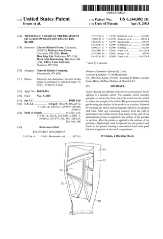
  • 5. US 6,544,002 B1 3 Other features and advantages of the present invention will be apparent from the following more detailed descrip tion of the preferred embodiment, taken in conjunction with the accompanying drawings which illustrate, by way of example, the principles of the invention. BRIEF DESCRIPTION OF THE DRAWINGS FIG. 1 is a perspective of an aircraft engine fan blade, showing pockets formed therein; FIG. 2 is a graph of the performance ofseveral different titanium Surface preparationsasa function offracture tough ness at 310 F. DETAILED DESCRIPTION OF THE INVENTION This invention is directed toward the chemical treatment of a metallic fan blade, Such as used in jet engines, that has been machined to produce a preselected number of pockets in preselected locations on the blade. One such fan blade 10 is depicted in FIG. 1, showing pockets 12 formed in the airfoil surface 14. The purpose ofthis chemical treatment is to attain improved bond strength between the metallic blade pockets and the primer coat which is applied to the Surface of the blade pockets, and to attain greater bond Strength between a polymeric resin that comprises the lightweight inserts and the primer coat. The fan blade also has a dovetail portion 16, which does not undergo chemical treatment. Fan blades used in jet engines consist of a blade portion and a dovetail portion which attaches a blade to the fan disc. The dovetail portion of the part requires no chemical treatment, and this invention is directed to the airfoil portion of the blade. The airfoil portion of the blade should first be inspected to ensure that there are no nicks, dings, bent or deformed material, and that there is no unusual discoloration. Pockets are machined or cast into the Surface of the blade. The as-manufactured Surface finish on the pockets of the airfoil portion ofthe blade is notcriticalto the process ofproducing an optimized Surface for bonding an insert within a pocket. The airfoil portion of the blade optionally may be cleaned prior to thisprocess to remove any foreign material from the surface. Afixture on which the dovetail portion of the blade is to be hung for Subsequent processing in accordance with this invention should be inspected to ensure that the blade is held rigidly without movement thatcan damage the edges of the airfoil portion of the blade. This process makes use ofdeionized water in a number of the proceSS Steps. The deionized water used in this proceSS should have a pH in the range of about 6.5 to about 7.5 and have a resistivity of at least about 50,000 ohms/cm in order to minimize Smut formation on the blade. Smut formation is detrimental to bonding and should be eliminated or reduced to the maximum extent possible. The first Step in the process of the present invention is to grit blast at leastthe surface ofthe airfoilportion ofthe blade that includes the pockets with a preselected grit type at a preSelected pressure for a preselected period of time. The purpose of the grit blasting is to obtain a Substantially even surface finish to increase the ability of the primer to bond to the metallic Surface of the pockets. In a preferred embodiment, the Surface ofthe blade pockets are gritblasted usingAl-O, the size of the grit being in the range of about 120grit to about 180grit, at a pressure in the range of about 40 to about 60 psi. Oxides of other materials such as refractory metal oxides, for example ZrO or SiO may be 5 15 25 35 40 45 50 55 60 65 4 substituted for alumnia. The dovetail portion of the part typically is masked So that it is unaffected by grit blasting. After the grit blasting is complete, the Surface of the airfoil portion of the blade that was grit blasted is rinsed. In one embodiment, the airfoil portion of the blade is rinsed with deionized water for a preselected period of time to remove any loose particles from the Surface of the blade. In a preferred embodiment, the airfoil portion of the blade is Sprayed with deionized water for at least about three min utes. In an alternate embodiment, the blade is rinsed with a Solvent which is miscible with water, and which has a volatility sufficient to accelerate the removal of liquid from the surface of the blade without leaving a stain. Desirably, the Solvent also can remove any grease and other contami nants from the Surface ofthe blade. The solvent used to rinse the airfoil portion of the blade is preferably an alcohol Selected from the group consisting of ethanol, propanol, methanol or isopropyl alcohol. Isopropyl alcohol is the preferred alcohol used to rinse the part. Once the part has been rinsed with the solvent, it may be wiped with a Solvent-Saturated cloth and dried with a lint-free cloth. Drying is accomplished to prevent the formation of water Stains. These water Stains have been found to detrimentally affect bonding of the insert within a pocket. The airfoil portion of the blade is then immersed in an alkaline etch bath in order to complete the creation of a proper Surface finish for the application of a primer coat. If deionized water was used to rinse the airfoil portion of the blade, the airfoil portion of the blade must be immersed in an alkaline etch bath before the water dries on the Surface of the blade to prevent formation of water stains. The water Stains detrimentally affect the adhesion of Subsequently applied primer.The dovetail portion ofthe blade typically is not immersed in the alkaline etchbath.As a practical matter, the tank that contains the alkaline etch bath should be made of a material or materials which are non-reactive with the alkaline bath in order to prevent the dissolution of any portion of the tank into the solution of the bath. The preferred alkaline component of the bath is TURCO 5578, a proprietary alkaline Solute which is currently manufactured by Elf Atochem. TURCO 5578 is comprised primarily of NaOH and traces of petroleum distillates. The preferred composition of the alkaline etch bath is deionized water combined with a Sufficient amount of TURCO 5578 in Solution to ensure that the concentration ofthe TURCO 5578 is about 360 to about 480 grams of TURCO 5578 per liter of deionized water. Additionally, a preselected amount of ferric Sulfate is added to the TURCO 5578 Solution to ensure a concentration ofiron ofabout 0.05 to about 0.15 gramsper liter of deionized water. The addition of ferric Sulfate to the alkaline etch bath maintains an iron concentration in the bath so that the etch rate is not greatly affected by the build up of dissolved Timetal in the bath solution. The temperature of the bath shouldbe in the range ofabout 180° F to about 185 F. to minimize Smut formation and provide a relatively even etch. The airfoil portion of the blade should remain in the bath for a preselected period of time Sufficient to provide a uniform surface finish. Preferably, the airfoil portion of the blade should remain in the bath for a time of about 15 to about 17 minutes. Continuous agitation of the alkaline etch bath is preferable in order to further reduce Smut formation on the airfoil portion of the blade. The etch rate of the titanium or titanium alloy should preferably be about 0.3 mils to about 0.7 mils per hour. The concentration of titanium in the alkaline etch bath should preferably not exceed 120 parts per million during the etching process to maintain the proper etch rate.
  • 6. US 6,544,002 B1 S As the airfoil portion of the blade is removed from the alkaline bath, the airfoil portion of the blade is continuously rinsed with deionized water for a preselected period of time in order to prevent any solute from the alkaline bath from drying on the part and leaving a Stain on the part. The rinse Step preferably has a duration of at least three minutes in order to wash most of the alkaline solution from the airfoil portion ofthe blade. During the rinsingprocedure, the airfoil portion of the blade optionally may be brushed to remove any Smut that may be formed. In a preferred embodiment, the brush used should be a soft brush made of a synthetic material, Such as a nylon brush, to avoid removing addi tional metal from the surface of the airfoil portion of the blade. The airfoil portion of the blade remains wet while it is being brushed in order to prevent the airfoil portion ofthe blade from drying with resultant formation of water stains on the Surface which adversely affect adhesion of primer. Once the Smut has been removed from the Surface of the airfoil portion ofthe blade, the airfoil portion of the blade is placed into an immersion bath of deionized water at a preSelected temperature, for a preselected period of time in order to neutralize any remaining alkaline Solution. The tank that contains the deionized water bath is comprised of a material or materials that are non-reactive with the deionized waterbath in order to prevent the dissolution ofany portion of the tank into the water bath. The deionized water bath is maintained at the preselected temperature during the entire time that the airfoil portion ofthe blade is in the bath. Once the airfoil portion of the blade is placed into the immersion bath, the bath is agitated for a preselected period of time to minimize Smut formation on the airfoil portion of the blade. In a preferred embodiment, the temperature of the immer sion bath should remain in the range of about 165 F. to about 185 F. Ifthe temperature ofthe water is much higher than about 185 F., then water flashes upon removal of the blade and stains form. If the temperature is lower that about 165 F., then Smut formation on the blade is promoted, which is still hot from the alkaline treatment. The airfoil portion of the blade should remain in the bath for a period oftime not to exceed three minutes to prevent the formation of Smut on the airfoil portion of the blade. As the airfoil portion of the blade is being removed from the deionized water bath, it is continuously sprayed with deionized water at a preselected temperature in order to prevent any water Stains from forming on the hot airfoil portion of the blade. The deionized water used in the spray is preferably at room temperature in order to prevent the deionized water from rapidly drying on the Surface of the airfoil portion of the blade and leaving water marks. The airfoil portion of the blade should be sprayed for at least three minutes. After the airfoil portion of the blade is removed from the deionized water bath, it may be brushed to remove any Smut which formed on the airfoil portion of the blade during the deionized water bath. In a preferred embodiment, the brush is a Soft, Synthetic preferably nylon brush in order to avoid Scraping any metal offofthe Surface of the blade. Once the part has been brushed, it is placed into a Spray rinse comprised of deionized water within a preselected temperature range, for a preselected period of time in order to remove any alkaline Solution remaining on the blade. In a preferred embodiment, the temperature of the Spray rinse is maintained at room temperature for the duration of the Spray Step in order to prevent the deionized water from drying on the Surface of the blade and leaving water Stains. AS the part is being removed from the deionized water Spray, and before any portion of the part is allowed to dry, 15 25 35 40 45 50 55 60 65 6 the part is visually inspected to determine if it there are any waterbreakson the Surface oftheblade pockets. Ifany water break is evident, indicative ofa Stain or an impurity, the part must be reprocessed, beginning with immersion in the alkaline bath. If the part requires reprocessing, it should be placed into the alkaline bath before any of the water on the Surface of the blade dries in order to prevent water Stains from forming on the surface of the blade. After the part has been inspected Successfully for any water breaks, and found to be free of water breaks, the part is immersed in an acid bath comprising deionized water and a preselected concentration of nitric acid for a preselected period of time. The purpose of the bath is neutralize any remaining alkaline etch Solution remaining on the Surface of the blade. Upon immersion of the blade into this bath, the bath is agitated for a preselected period of time. The acid bath shouldpreferably include asolution about 1 to about 15 percent nitric acid by mass in deionized water in order to neutralize any remaining alkaline Solution on the blade. In a preferred embodiment, the acid Solution is about ten percent nitric acid. The temperature of the acid bath is preferably in the range ofabout 65 F. to 85 F. and the blade is immersed in the acid bath for a time of about one to about two minutes in order to minimize the formation of Smut on the blade. While the airfoil portion of the blade is being removed from the acidbath, it iscontinuously sprayed with deionized water at a preselected temperature in order to prevent the acid Solution from drying on the blade and leaving any marks on the blade. The blade is rinsed for at least three minutes in order to remove any acid Solution remaining on the surface of the blade. While the blade is being rinsed, it preferably is brushed to remove any Smut which formed during the acid bath. In a preferred embodiment, the blade is brushed with a wet nylon brush in order to prevent any metal from being removed from the blade. In a preferred embodiment, the temperature of the Spray rinse is main tained at room temperature for the duration ofthe Spray Step in order to minimize evaporation of the water which would leave water stains on the airfoil portion of the blade. As the airfoil portion of the blade is removed from the deionized water Spray rinse, the blade is inspected for any water break. If the blade shows any water break, it must be processed again beginningwith the alkaline bath. The airfoil portion of the blade must be placed in the alkaline etch bath before any portion of the airfoil portion of the blade is allowed to dry in order to prevent the any water Stains from forming on the Surface of the airfoil portion blade. After the part hasbeen checked for water break and if no water break is found, the part may be rinsed with a Solvent which is miscible with water,which will not cause a stain on the Surface of the blade, and which will remove any grease and other contaminants from the Surface of the blade. The Solvent used to rinse the blade is preferably an alcohol, as previously set forth. Once the part has been rinsed with the Solvent, it may be wiped with a Solvent Saturated cloth and dried with a lint-free cloth. The blade is then dried using forced air in a fresh air circulating oven at a preselected temperature for preselected period of time. The airfoil portion of the blade preferably is dried for a period oftime between about 10 minutes to about 60minutesat a temperature between about 130 F. and about 300 F. and preferably between about 30 minutes and about 60minutesat a temperature between about 135 F. and about 180° F. or alternatively for a period of time between about 10 minutes and about 30 minutes at a temperature between about 250 F. and about 300° F in order to thoroughly dry the blade. The blade then is dried with a lint-free cloth.
  • 7. US 6,544,002 B1 7 Within twenty four hours ofthe drying step, the surface of the blade pockets are coated with a Standard non-chromated Spray primer to achieve a preselected cured primer thick neSS. If a chromated primer is used, a weaker bond will be formed between the surface of the blade and the primer and a weaker bond will be formed between the polymer resin used for the insert and the primer. The preferred polymer currently is polyurethane resin, although other resins dis playing Similar properties may be Substituted. If more than twenty four hours passes between the drying Step arid the application of the primer, a relatively large amount of titanium oxide, caused by reaction of air with the Surface of the titanium alloy blade will form on the surface ofthe blade which will ultimately weaken the bond between the metal Surface of the pockets and the lightweight inserts. The amountofprimercoatthickneSS applied to the blade pockets preferably is sufficient to obtain a cured thickness between about 0.00002 and about 0.00020 inches. In a preferred embodiment, the primer is TYPLY BNF), a proprietary non-chromated primer available from Lord Corporation of Erie, Pa. Once the primer has been applied to the blade pockets, the primer is cured in two stages at pre-Selected temperatures and for pre-Selected periods of time. The primer preferably is cured for a minimum of 30 minutes at a temperature range ofabout 65 F. to about 85 F. and then immediately followed by curing in the range of about 60 minutes to about 90 minutes at a temperature in the range of about 250 F. to about 300° F. The resin is applied as set forth in U.S. patent application Ser. No. 09/044,255 incor porated herein by reference. The blade pockets that are prepared using the methods and procedures of the present invention display improved fracture toughness at 310 F. when compared to blades having pockets prepared using various other methods. The fracture toughness performance of finished blades having pockets prepared by Several techniques and then having the pockets filled with the same polyurethane resin as well asby the methods Set out by the current invention preparation techniques prior to applying a primer are Set forth in FIG. 2, all ofwhich were tested at about 310 F. Each method refers to the method preparation techniques prior to applying a primer. AS can be seen, the mode 1 fracture toughness of blade pockets prepared in accordance with the present invention displays a significant improvement over the base line method of grit blasting using 36 grit at 80 psi. FIG. 2. is a graph that illustrates the improvement that the present invention provides over other possible fan blade treatments. Five data points were gathered for each type of treatment. The lines running vertically illustrate the maxi mum and the minimum Mode 1 fracture toughness at 310 F. The shaded rectangles represent 75% of the data points gathered for each type of treatment. The horizontal line within the shaded rectangle represents the mean value of the data points. The black dot within the Shaded rectangle represents the median value of the data points. As shown in FIG. 2, looking to the mean of the data points,peening with an intensity of 6-10 N on the Almen N Scale and 120 grit at 50 psi produced a fracture toughneSS equivalent to the toughness of the baseline method, while peening with less intensity, 6-10 A on the Almen A Scale produced an inferior fracture toughness. Without any pre treatment of the pockets, a fracture toughneSS was obtained intermediate between the two methods employing peening. However, the present invention yielded fracture toughneSS improvements over the baseline method of between about 70% to about 200%. While the invention has been described with reference to a preferred embodiment, it will be understood by those 15 25 35 40 45 50 55 60 65 8 skilled in the art that various changes may be made and equivalents may be substituted for elements thereof without departing from the Scope ofthe invention. In addition, many modifications may be made to adapt a particular situation or material to the teachings of the invention without departing from the essential Scope thereof. Therefore, it is intended that the invention not be limited to the particular embodi ment disclosed as the best mode contemplated for carrying out this invention, but that the invention will include all embodiments falling within the Scope of the appended claims. What is claimed is: 1. A method of producing an aircraft engine blade, com prising an airfoil portion and a dovetail portion, and having atleast one pocketin the airfoilportion,comprisingthe Steps of: providing an aircraft engine fan blade having at least one pocket in the airfoil portion; grit blasting a Surface ofthe airfoil portion having at least one blade pocket with a preselected type of grit, at a preSelected Size and at a preselected pressure to effect a uniform Surface finish; Washing the Surface with a Solvent that is miscible in water and has a volatility Sufficient to accelerate the removal of liquid from the Surface without leaving a Stain; drying the Surface by removing the Solvent; immersing the airfoil portion of the blade in an alkaline etch bath while agitating the etch bath to further effect a uniform Surface finish; removing the airfoil portion of the blade from the bath without allowing the airfoil portion of the blade to dry; neutralizing the alkaline Solution on the Surface of the airfoil portion of the blade; Washing the Surface with a Solvent; drying the Surface wherein the Solvent is removed from the surface of the airfoil portion of the blade without forming Stains, applying a primer to the at least one pocket of the airfoil portion of the blade; curing the primer; injecting a polymeric resin into the at least one pocket; and curing the resin. 2. The method of claim 1, wherein the alkaline etch bath further comprises a preselected concentration of NaOH and a predetermined iron concentration. 3. The method of claim 2, wherein the concentration of NaOH is about 360 grams to about 480 grams per liter of deionized water and the concentration of iron is about 0.05 to about 0.15 grams per liter of deionized water. 4. The method of claim 3, wherein the NaOH solution is TURCO 5578 in deionized water. 5. The method ofclaim 1, wherein the step ofneutralizing further comprises the Step of immersing the airfoil portion of the blade in a deionized water bath at a preselected temperature for a prese lected period of time. 6. The method ofclaim 1, wherein the step ofneutralizing further comprises the Step of immersing the airfoil portion of the blade in an acid Solution, having a predetermined concentration, at a preSelected temperature for a preselected period of time.
  • 8. US 6,544,002 B1 9 7. The method as in claim 6, wherein the step of neutral izing further comprises the Step of: immersing the airfoil portion of the blade in a deionized water bath at a preselected temperature for a prese lected period of time after immersion in the acid Solution. 8. The method ofclaim 1, wherein the step ofneutralizing further comprises the Steps of immersing the airfoil portion of the blade in a deionized water bath at a preselected temperature for a prese lected period of time, immersing the airfoil portion of the blade in a nitric acid Solution, having a predetermined concentration, at a preSelected temperature for a preselected period of time. 9. The method of claim 8, wherein the acid is nitric acid having a predetermined concentration. 10. The method of claim 9, wherein the nitric acid has a concentration of about 1% to about 15% by mass in deion ized water. 11. The method of claim 1, wherein each washing step includes a Solvent Selected from the group consisting of ethanol, propanol, methanol and isopropyl alcohol. 15 10 12. The method of claim 11, wherein the solvent is isopropyl alcohol. 13. The method of claim 1 wherein the type of grit is Selected from the group consisting of oxides of refractory metals. 14. The method of claim 13 wherein the grit is selected from the group consisting of Al-O, SiO, ZrO2. 15. The method of claim 14 wherein the grit is Al-O. 16. The method of claim 15 wherein the size of the grit used is in the range of about 120 grit to about 180 grit. 17.The method ofclaim 16 wherein the pressure used for the grit blasting is in the range of about 40 psi to about 60 pS1. 18.An aircraft engine fan blade having at least one pocket fabricated into the airfoil portion manufactured by the process of claim 1. 19. An aircraft engine fan blade having at least one pocket, Said at least one pocket being filled with a resin, wherein the fracture toughness between the resin and metal Surfaces of the pocket is characterized as being at least 4.4 in-lbs/in’.
  • 9. UNITED STATES PATENT AND TRADEMARK OFFICE CERTIFICATE OF CORRECTION PATENT NO. : 6,544,002 B1 Page 1 of 1 DATED : April 8, 2003 INVENTOR(S) : Charles Richard Evans et al. It is certified that error appears in the above-identified patent andthat said Letters Patent is hereby corrected as shown below: Column 7 Line 10, "arid Should be -- and --. Signed and Sealed this Twenty-second Day of February, 2005 WDJ JON W. DUDAS Director ofthe United States Patent and Trademark Office
  • 10. UNITED STATES PATENT AND TRADEMARK OFFICE CERTIFICATE OF CORRECTION PATENT NO. : 6,544,002 B1 Page 1 of 1 DATED : April 8, 2003 INVENTOR(S) : Charles Richard Evans et al. It is certified that error appears in the above-identified patent andthat said Letters Patent is hereby corrected as shown below: Column 7 Line 29, “09/044,255” should be -- 09/440,255 --. Signed and Sealed this Seventh Day ofJune, 2005 WDJ JON W. DUDAS Director ofthe United States Patent and Trademark Office